Computer Aided Design
This weeks assignment:
- compress your images and videos
- post a description with your design files on your class page
- model (raster, vector, 2D, 3D, render, animate, simulate, ...) a possible final project
- MyPaint - Raster 2D
- Inkscape - Vector 2D
- Fusion 360 - 3D
Compressing images and videos
compressing images
Due to our upload limit on storage space for this website, we are forced to compress the typically high-resolution images
we take before using them here. For images, in my case, I use Microsoft PowerToys,
which can be downloaded here.
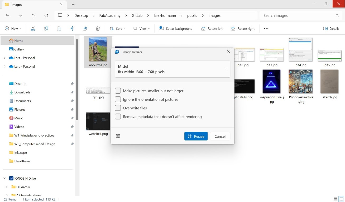
After installation, it is extremely easy to use. All you have to do is go to the folder where the image or images you want to compress are stored,
select one or more images and then right-click and select "Resize with Image Resizer". This opens the Image Resizer menu, which is included in
Microsoft PowerToys, among other things. Here we can select how high the resolution of the image should be in the end and have other options to
choose from. I am personally a fan of activating the "Overwrite files" option to avoid renaming later. With "Resize" we can compress with the
selected parameters and confirm; after that our images should be smaller at best. We can check this by right-clicking on them and displaying the
"Properties". There you will find the item size.
compressing videos
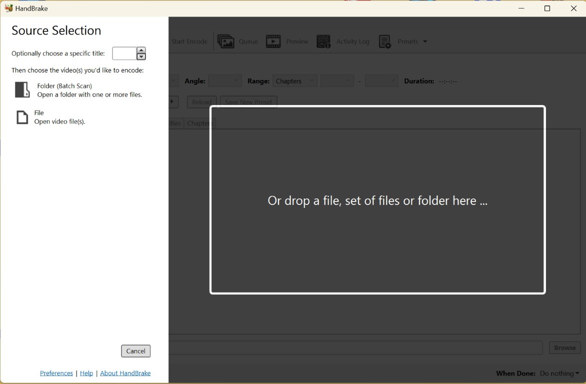
Unfortunately, you need a different tool to compress videos. Based on Neil's recommendation last week, I use the
HandBrake software
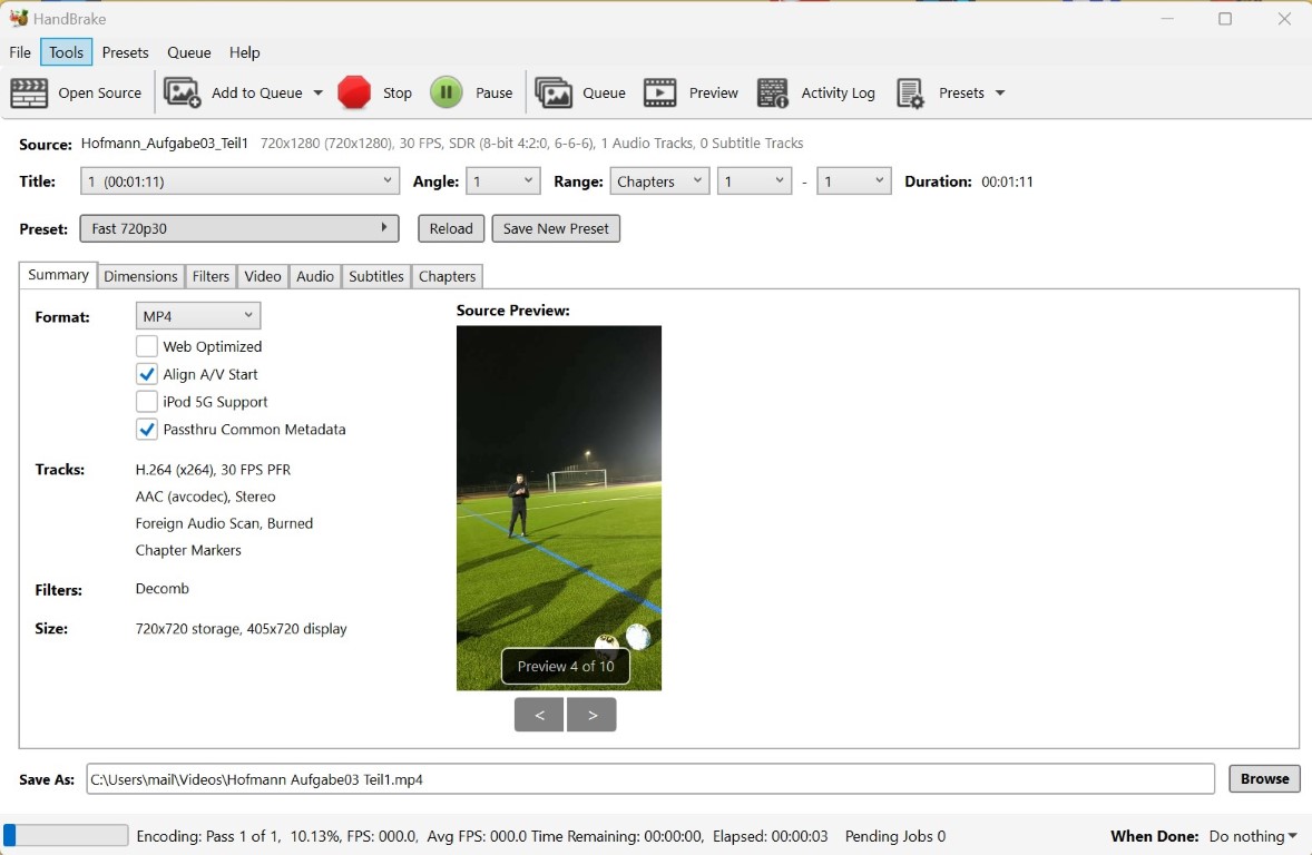
for this, which I have also found to be very user-friendly in practice. After installing and opening the program, the dialog below
appears, in which I have inserted a video of myself from this week using drag and drop.
As you can see, the video even opens in the preview and the program gives you a range of possible resolutions. In this case, I reduced the preset from 1080p and 30fps to 720p and 30fps because that was enough quality. The file was originally recorded by the phone in 1080p and had a size of 37.5 MB; after compression, the file is only 20.9 MB. The track or the H.264 (x264) encryption is important when compressing, because other types may not be able to be played on all devices. After selecting a storage path, we can compress the video using the green "Start Encode" button. We are then informed about the process via the lower status bar and can then find the compressed video under the specified storage path.
Computer Aided Design
raster based 2D design
This week, to see and demonstrate the differences, I made similar 2D designs in different programs. The first program I used was
MyPaint,
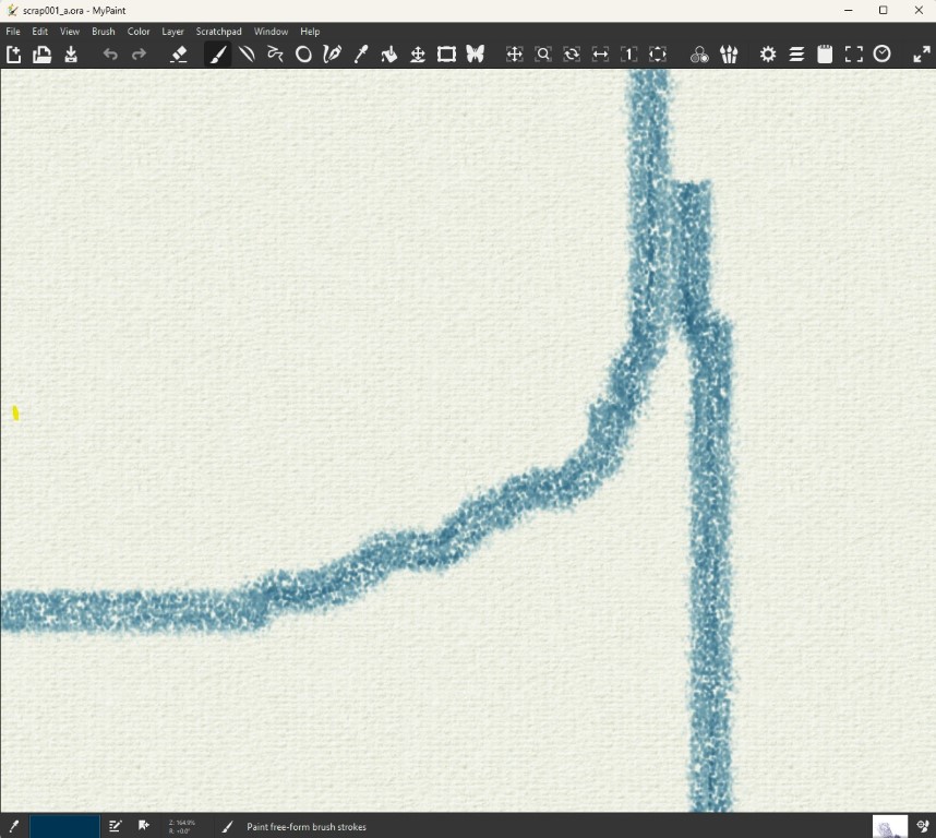
which works on a grid or pixel basis. This means that the program creates a grid, just like the individual pixels in the screen you are reading
this on. Your screen sets a color value for each pixel. I will try to show what this means here with images of different resolutions.
You see a picture of a dog
side by side, at the top with a resolution of 720 by 480 pixels (length by height), at the bottom with 20 by 20 pixels for clarity. At the top
you can still recognize the dog very well, at the bottom it would be more difficult to make out who the good boy is.


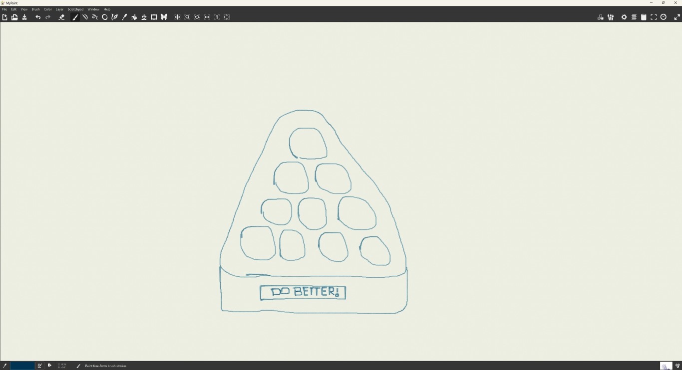
To create a simple example, I used the sketch of my final project from last week again. After installing and starting the program, a new file with a neutral background appears. In this file, you can then draw anything your heart desires using the various tools at the top or the different pens and brushes. In my case, unfortunately, this had to be done with the mouse because I don't have a tablet. In combination with my previously very hidden talent for drawing, this is the result.
vector based 2D design
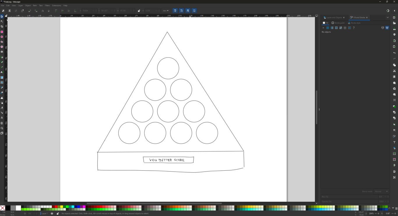
The problems shown above are solved by vectorizing images. Vector graphics are defined mathematically with real coordinates. Objects such as the following sketch are described by
lines, circles and other shapes that have or connect real coordinates. This allows you to work as you like when zooming into the objects without losing focus. In the same way, modern
machines like mathematical descriptions and coordinates because they allow you to work very precisely and with repeatable accuracy.
Typical file formats are .svg and .pdf, along with many others that are less well known.
In this case I worked with the program Inkscape, which is freely available.
It's a good and powerful software, but it certainly doesn't hurt to watch a tutorial before you start. I don't have a specific recommendation for this,
because I could already do what I needed to with Inkscape. The probably more important question is whether it will still be like this in a few weeks - so maybe a recommendation will follow.
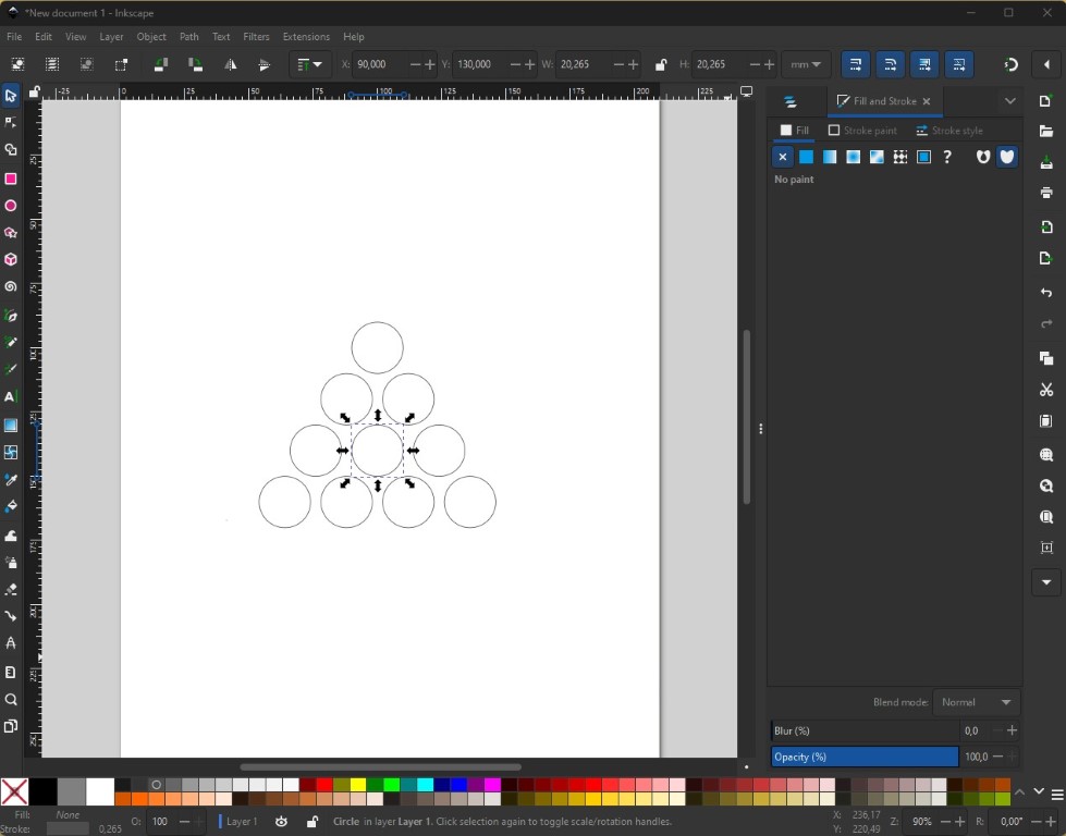
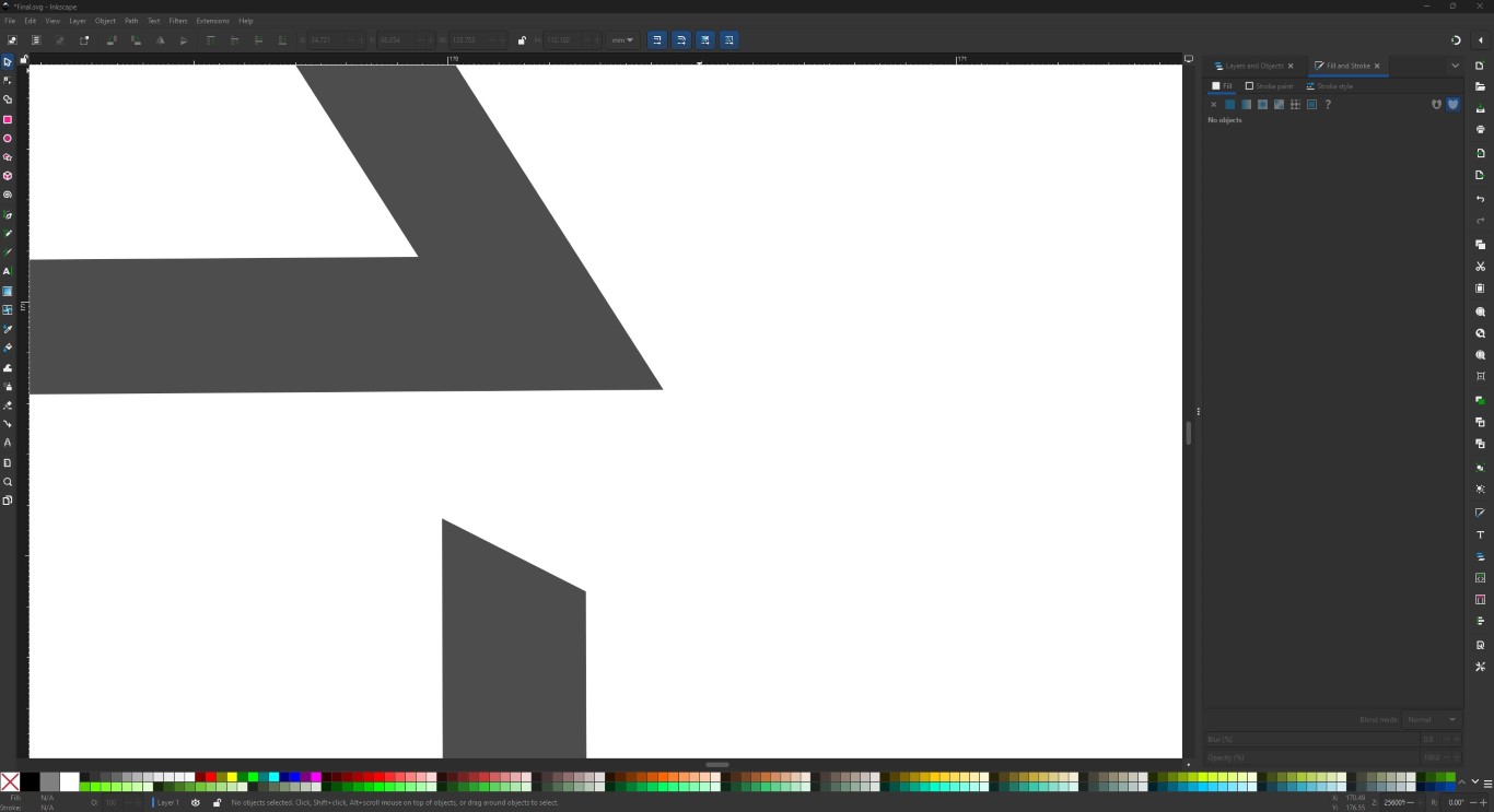
When Inkscape is installed and you open it, you first have to create a new project. Once you have done that, the program opens as shown below, with fewer circles, i.e. a blank sheet of paper.
Creating the circles was my first task, starting with a circle to which I assigned a diameter of 20.265 mm because I wanted 20 mm and didn't look any further. The normal keyboard commands for
Windows in my case also work within the program, so I duplicated my circle using copy and paste. As described above, there are various references to mathematics in Inkscape, but for the design
in the top bar, the values for x, y, w and h were important to me. X is the X value of the coordinate of the top left corner of the square that was drawn around the selected circle.
Similarly, Y is the Y coordinate. W stands for width and H stands for height, which defines the dimensions of the object itself, in this case the circle.
3D design
Lastly, or in my case the most important thing for later production, is the 3D design. I used Fusion360 for this because I am already familiar with it. In general, we create so-called sketches
in 3D design, just like in vector design. From these sketches, we use various operations to generate 3D bodies to which we can also assign surface properties, as shown in the images, so that
we can get an impression of what what we are designing will actually look like in the end. I also recommend looking at tutorials for Fusion360.
Autodesk itself provides tutorials. 3D design
is quite complex and very diverse, so I would recommend trying out what you see in practice straight away, because the overall scope would definitely be overwhelming.
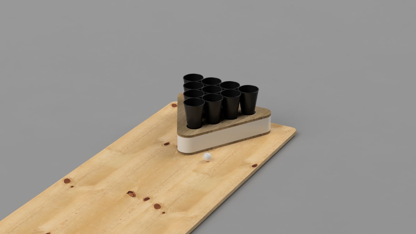
Here I will briefly describe a few steps on the way to the 3D design of my final project. The design process is very quick but can be seen in full in the video for week 2 on my final project page.
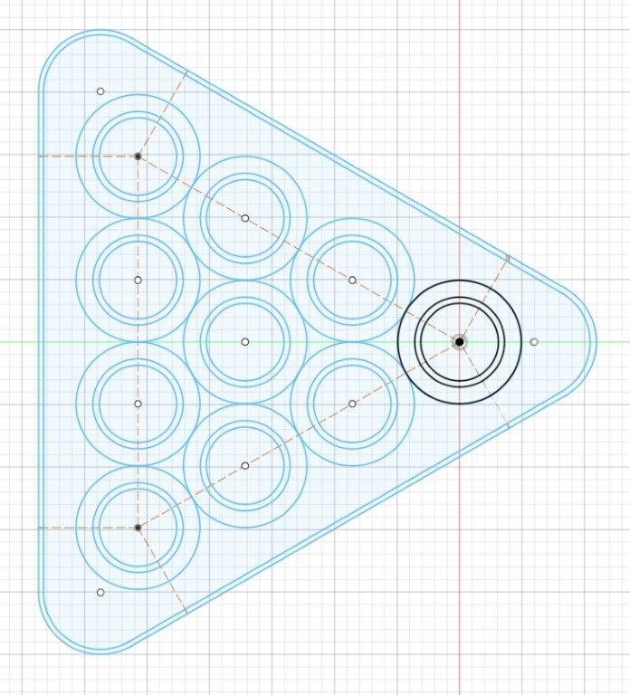
As you can see on the left, I made two sketches for the entire project. One of them is just for the cups because I needed a different layer reference here.
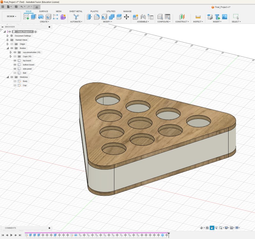
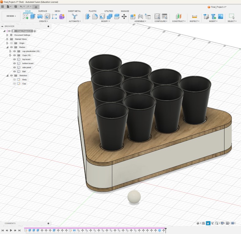
During the rendering process, I also created a table top in CAD, as in the tutorial. To get into render mode, you switch the area or the drop-down menu in the top left from "Design" to "Render" and have fun with different sceneries. I also tested several backgrounds, but didn't really like any of them, so this week's hero shot is against a flat gray background, but nicely rendered. In that sense, that's it. For the spectacular animation and the design process in the video, please refer to the subpage of my final project. All further developments will also be found there.