14. Interface and Application Programming
| Task | Status |
|---|---|
| Linked to the group assignment page | ✅ Done |
| Documented your process | ✅ Done |
| Explained the UI you made and how you implemented it | ✅ Done |
| Explained how your application communicates with your embedded board | ✅ Done |
| Included original source code (or screenshot if code not available) | ✅ Done |
| Included a ‘hero shot’ of your application running & communicating with your board | ✅ Done |
Heroshot
Group Assignment
- Compare as many tool options as possible.
- Document your work on the group work page and reflect on your individual page what you learned.
Some Key Takeways from the group assignment
- Explored the wireless communication with the different interface
- Rico’s tutorial has been a great tool to explore on processors
- learnt how to create a GUI using ControlP5 in Processing.
Link to group assignment is here
Individual Assignment
- Write an application that interfaces a user with an input &/or output device that you made.
Blynk
Blynk is a platform that helps you connect microcontrollers like Arduino and Raspberry Pi to the internet.
It supports different ways to connect your board to the Blynk Cloud or your own Blynk server. These include:
-
Ethernet
-
Wi-Fi
-
Bluetooth
-
Cellular
-
Serial
Blynk has three main parts:
Blynk app builder – Lets you create apps using widgets. It works on Android and iOS.
Blynk server – Manages communication between your phone and the hardware. You can use the Blynk Cloud or set up your own local server. It’s open source and runs even on a Raspberry Pi.
Blynk libraries* – Help your microcontroller talk to the server and handle commands from the app. They support many popular boards.
Here, I used Blynk as both the interface and application layer to control a solenoid lock in a smart cabinet via WiFi. The Blynk mobile app served as the user interface, providing an intuitive dashboard with a virtual button to lock or unlock the solenoid remotely. On the application side, an ESP32-S3 microcontroller was programmed to connect to the Blynk cloud, listen for virtual pin commands, and trigger the solenoid accordingly. This setup allowed seamless communication between the user and the hardware, enabling real-time control and feedback. The integration of interface and application programming using Blynk ensured efficient interaction, remote access, and potential for future expansion.
I follow the youtube tutorial for setting up the blynk app.
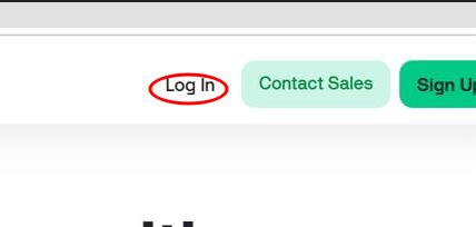
First create an account using the link. Click on log in.
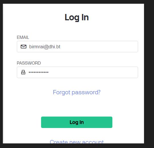
You add your username and password and click on login.
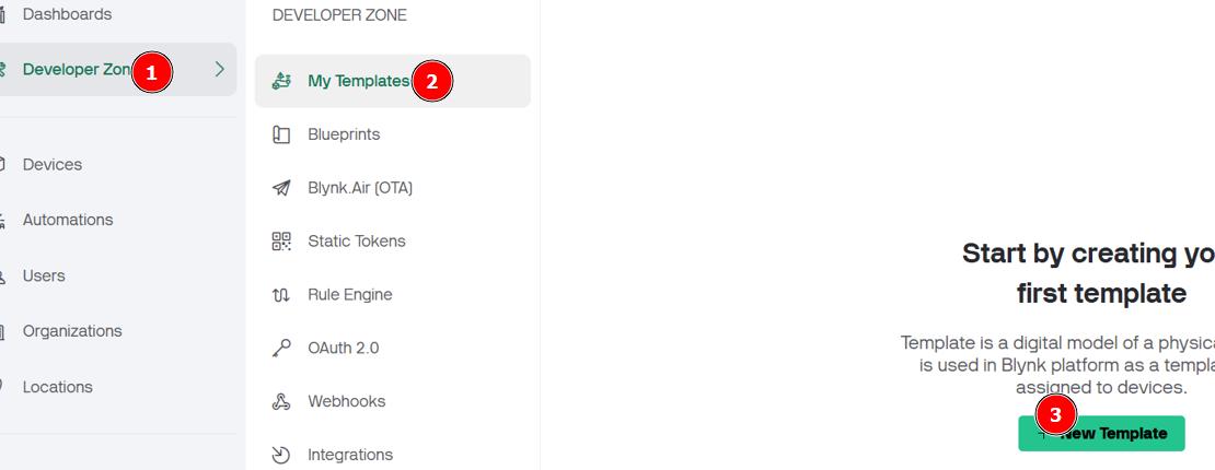
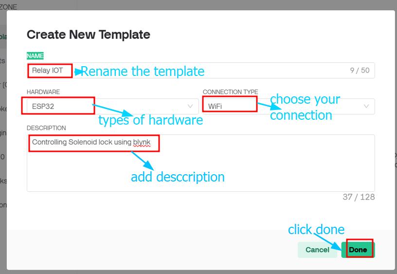
After logigging in, click on developer zone, create new template. After clicking on create new template, new dialog box pops up > add all the required data > Click on Done
Next click on datastream > Click on create datastream under the home icon button.
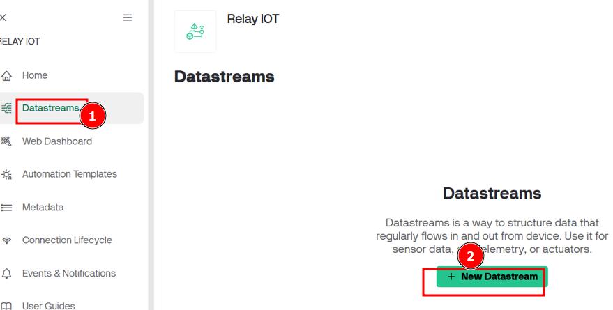
A new dialog box will pops up, after clicking on the create datastream. add all the parameters and click save
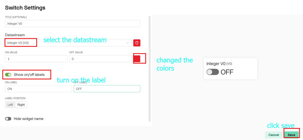
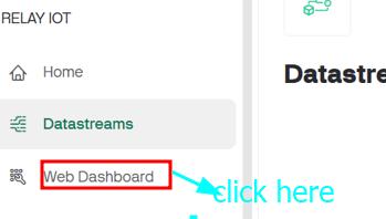
After creating datastream, click on web dashboard
From the widget box,Add a switch here so that you can control your solenoid via blynk app. Also add switch parameter and clik on save.
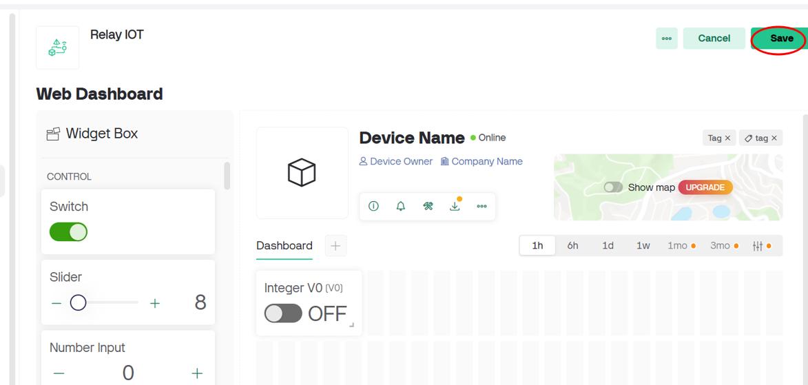
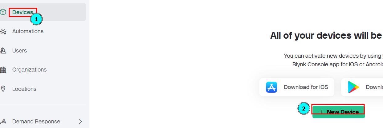
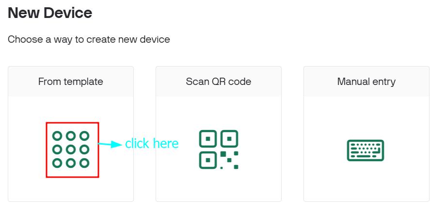
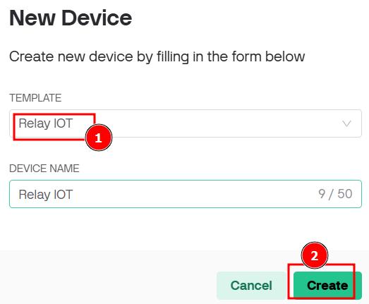
After creating web dashboard, click on device> new device > From template > select the template for new device > click on create as shown in the images below.
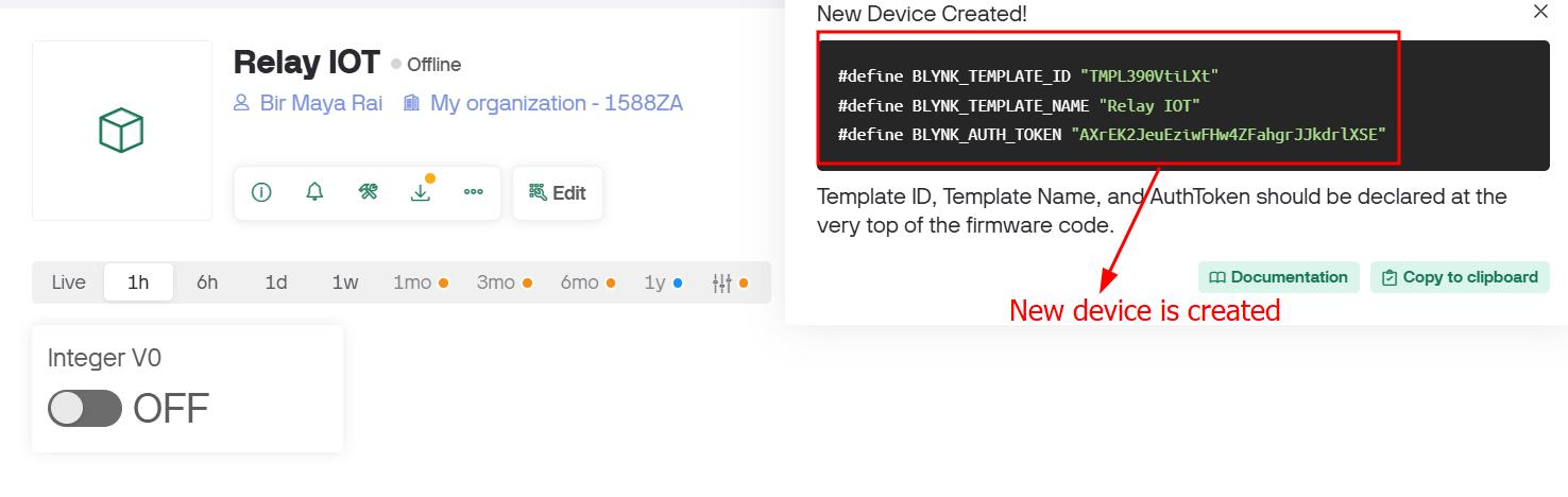
After clicking the create, a token and Wi-Fi credentials will be automatically generated. Copy them and paste them at the top of your code to establish a remote connection between your simulator and Blynk.
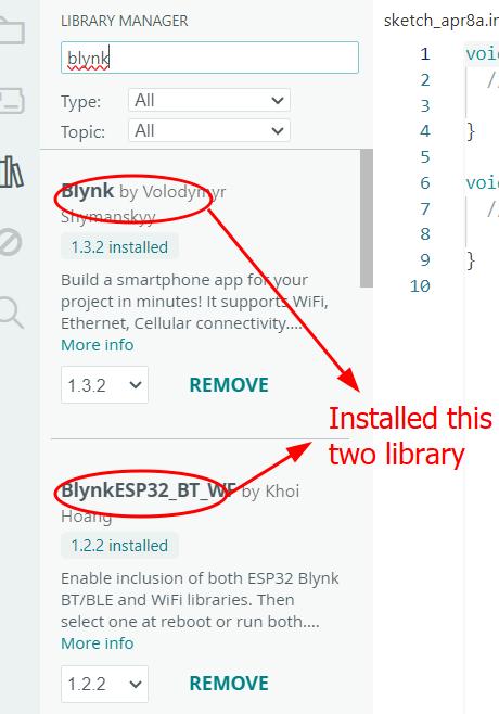
Open arduino IDE > add the blynk library by Volddymyr shaymanskyy and khoi hoang
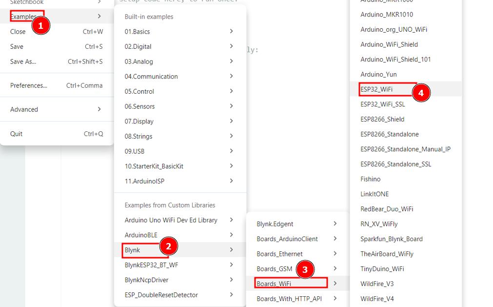
I am going to edit the code on top of the examples code
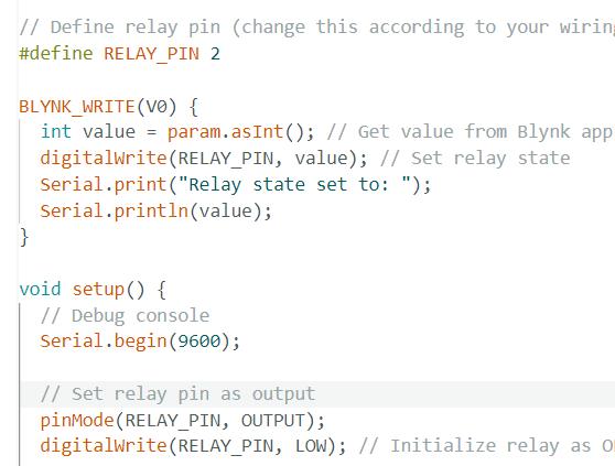
Edited code as shown in the image below(what I added)
📌
  /*************************************************************
  Blynk + ESP32 Relay Control Example

  Make sure to install the ESP32 board package and the Blynk library.

 Replace the WiFi and Blynk credentials with your own.
*************************************************************/

 #define BLYNK_PRINT Serial

 // Blynk credentials
 #define BLYNK_TEMPLATE_ID "TMPL390VtiLXt"
 #define BLYNK_TEMPLATE_NAME "Relay IOT"
 #define BLYNK_AUTH_TOKEN "AXrEK2JeuEziwFHw4ZFahgrJJkdrlXSE"

 #include <WiFi.h>
 #include <WiFiClient.h>
 #include <BlynkSimpleEsp32.h>

 // WiFi credentials
  char ssid[] = "Fablab";
  char pass[] = "#JSW@2o25";

 // Define relay pin (change this according to your wiring)
 #define RELAY_PIN 2

 BLYNK_WRITE(V0) {
 int value = param.asInt(); // Get value from Blynk app
 digitalWrite(RELAY_PIN, value); // Set relay state
 Serial.print("Relay state set to: ");
 Serial.println(value);
 }

 void setup() {
 // Debug console
 Serial.begin(9600);

 // Set relay pin as output
 pinMode(RELAY_PIN, OUTPUT);
 digitalWrite(RELAY_PIN, LOW); // Initialize relay as OFF

 // Connect to Blynk
 Blynk.begin(BLYNK_AUTH_TOKEN, ssid, pass);
 }

 void loop() {
 Blynk.run();
 }
Once the code gets uploaded, Open serial monitor > select band of 9600, you will see what happening in the serial monitor
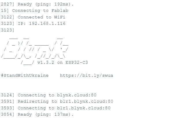
Also the device status will changed to online, which means I am ready to control the solenoid lock.
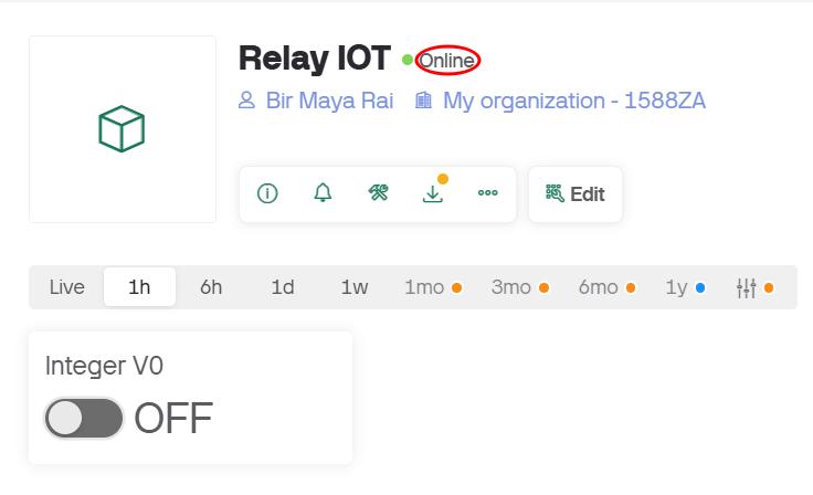
A short wokring video on Blynk device
Also, download the hightlighted blynk app in your phone. You can login using the same email id that you used to created the blynk new device in web browerser.

Once you login
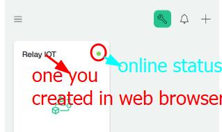
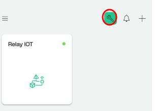
Click on the wrench icon on top left corner of the blynk app
Click on relay IOT
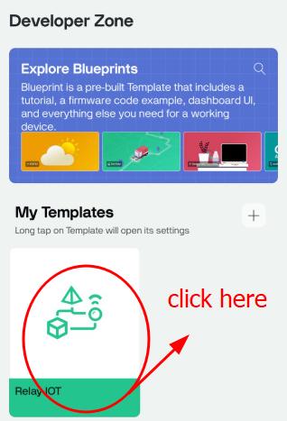
Click here to add the button to control the solenoid lock
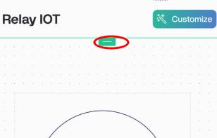
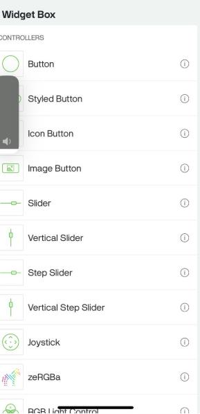
A widget box will pos up, add the required controllers(in my case button)
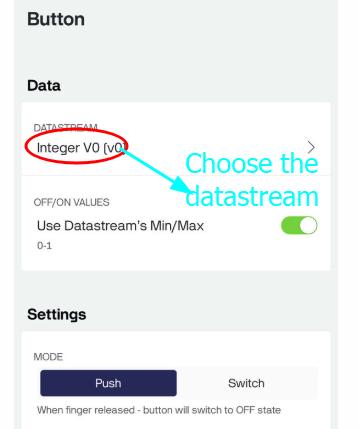
Click on contollers and add the datastream
How the code works?
This code XIAO ESP32C3 uses the Blynk IoT platform to enable Wi-Fi remote control of a relay connected to GPIO 2. It connects to the Blynk cloud using predefined credentials (BLYNK_TEMPLATE_ID, BLYNK_AUTH_TOKEN) and Wi-Fi network details (ssid, pass). The relay starts in the OFF state, and its operation is controlled via Blynk Virtual Pin V0—when a button in the Blynk app sends a command (1 for ON, 0 for OFF), the BLYNK_WRITE(V0) function updates the relay state accordingly while logging changes to the Serial Monitor. The loop() continuously runs Blynk.run() to maintain cloud communication, making this setup ideal for smart home automation, IoT appliances, or remote device control with real-time feedback.
Processor
Processing is an easy-to-use software and programming language designed to help people learn how to code, especially through visuals. Since 2001, it has helped people understand both technology and visual art. Today, many students, artists, designers, researchers, and hobbyists use Processing to learn and create new ideas.Processing looks similar to arduino IDE environment.
After following Rico San’s tutorial, I gained a comprehensive understanding of various features in Processing, including manipulating background colors, adjusting shape dimensions, and other graphical capabilities. The tutorial proved to be both insightful and informative.
To start with processing, I downloaded processing software from here
For this week’s assignment, I am using Processing. I want to control an LED on my board, which I programmed using the Arduino IDE. I will use the Processing interface to send commands through serial communication.
LED Control Interface Using Processing and Serial Communication
The Arduino listens for serial commands from Processing, turning an LED on/off at pin D6 based on received ‘1’ or ‘0’ signals.
Execute Arduino code first, then run the Processing sketch for seamless operation for the output scenario
I refer this code from Youtube tutorial and edited as per my requirements. For the Processors code, I refer the the link above and the follows Rico san tutorial.
I want to control the LED to turn ON and OFF from the button I made.
Firstly I made a window and a [ON] and [OFF] button with the code below.
       ControlP5 cp5;
      Serial myPort;

      void setup() {
      size(300, 300);

      cp5 = new ControlP5(this);

      // "Turn On" button - Pink
       cp5.addButton("turnOn")
       .setPosition(100, 50)
        .setSize(120, 70)
      .setColorBackground(color(255, 105, 180))  // Pink
       .setColorForeground(color(255, 182, 193))  // Light Pink on hover
           .setColorActive(color(255, 20, 147));      // Deep Pink on click

       // "Turn Off" button - Black
       cp5.addButton("turnOff")
      .setPosition(100, 150)
     .setSize(120, 70)
     .setColorBackground(color(0))              // Black
       .setColorForeground(color(50))             // Dark grey on hover
      .setColorActive(color(100));               // Lighter grey on click

     printArray(Serial.list());
      myPort = new Serial(this, Serial.list()[0], 9600); // Using first detected port
      }

      void draw() {
        background(128);  // Gray background (RGB: 128, 128, 128)
          fill(0);          // Black text
      textSize(20);
       text("LED CONTROL", 80, 30);
         }
Setting Up the GUI in Processing:
– I created window of size 300x300 pixels was created.
-
Two buttons were added using the ControlP5 library:
-
A “Turn On” button styled in pink.
-
A “Turn Off” button styled in black.
-
A title text “LED CONTROL” is displayed at the top of the window.
Initializing Serial Communication:
-
The Processing sketch lists available serial ports and connects to the first one automatically.
-
The baud rate is set to 9600, which must match the Arduino code.
Sending Data to Arduino:
-
When the “Turn On” button is clicked, the character ‘1’ is sent via serial.
-
When the “Turn Off” button is clicked, the character ‘0’ is sent.
Arduino Receives and Controls LED:
-
On the Arduino side, it listens for incoming serial data.
-
If it receives ‘1’, it turns the LED ON.
-
If it receives ‘0’, it turns the LED OFF.
For Arduino:
I modified the Arduino IDE code as per my requirement and changed the pin number to D6, as my LED is connected to that pin.
Start serial communication: Serial.begin(9600)
Arduino Code
📌
      const int LED_PIN = D6; // Use pin D6 on XIAO RP2040

      void setup() {
      Serial.begin(9600);          // Initialize serial communication
      pinMode(LED_PIN, OUTPUT);    // Set LED pin as output
       digitalWrite(LED_PIN, LOW);  // Start with LED off
       Serial.println("Ready to receive commands...");
       }

        void loop() {
         if (Serial.available() > 0) {
     char command = Serial.read();

      // Debug output (optional)
      Serial.print("Received: ");
      Serial.println(command);

      if (command == '1') {
      digitalWrite(LED_PIN, HIGH);
       Serial.println("LED ON");
     }
      else if (command == '0') {
      digitalWrite(LED_PIN, LOW);
       Serial.println("LED OFF");
      }
      }
        }
For Processing
I setup a function in Processing to control buttons that turn LEDs ON and OFF based on received characters. I’ve written the code to send specific characters when buttons are pressed, which the Arduino will interpret to control the corresponding LEDs.
-
Import serial library: import processing.serial.*;
: sketch > import library > Serial -
Add the highligted library as shown in the image below.
Sketch>Import library>Manages library > Search for the required library > Click Install
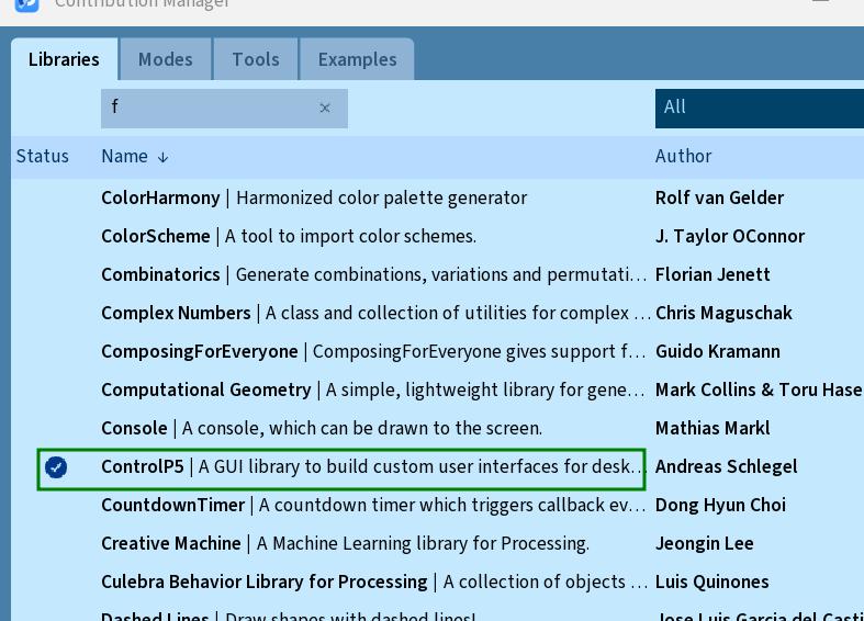
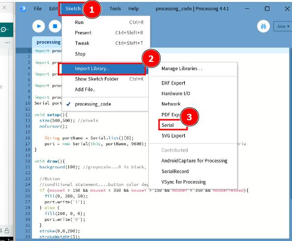
- Create a Serial object: Serial portName;
- Define portName: String portName = Serial.list()[0];
- Initialize Serial object: portName = new Serial(this, portName, 9600);
Processing Code
📌
    import processing.serial.*;
       import controlP5.*;

       ControlP5 cp5;
      Serial myPort;

      void setup() {
       size(300, 300);

      cp5 = new ControlP5(this);

        // "Turn On" button - Pink
          cp5.addButton("turnOn")
          .setPosition(100, 50)
        .setSize(120, 70)
       .setColorBackground(color(255, 105, 180))  // Pink
        .setColorForeground(color(255, 182, 193))  // Light Pink on hover
         .setColorActive(color(255, 20, 147));      // Deep Pink on click

      // "Turn Off" button - Black
      cp5.addButton("turnOff")
       .setPosition(100, 150)
      .setSize(120, 70)
       .setColorBackground(color(0))              // Black
     .setColorForeground(color(50))             // Dark grey on hover
        .setColorActive(color(100));               // Lighter grey on click

        printArray(Serial.list());
        myPort = new Serial(this, Serial.list()[0], 9600); // Using first detected port
      }

        void draw() {
       background(128);  // Gray background (RGB: 128, 128, 128)
        fill(0);          // Black text
      textSize(20);
       text("LED CONTROL", 80, 30);
      }


     void turnOn() {
      myPort.write('1');
     println("LED turned ON");
      }

     void turnOff() {
     myPort.write('0');
       println("LED turned OFF");
      }
Summary of the above code
-
Creates a simple interface with two buttons.
-
Sends ‘1’ or ‘0’ to the Arduino when buttons are clicked.
-
Arduino can read these values over the serial port and turn an LED on or off accordingly