4. Embedded Programming
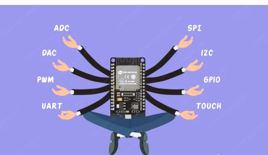
I found this image intersting and wanted to keep as my heroshot.
Task for the week04
Group Assignment
- Demonstrate and compare the toolchains and development workflows for available embedded architectures
Individual Assignment
-
Browse through the data sheet for your microcontroller
-
Write a program for a microcontroller and simulate its operation
Link to the group assignment is here
Note: Some Key takeaways from ESP 32 datasheet
- The ESP32-WROOM-32 is a compact, high-performance Wi-Fi and Bluetooth module based on the ESP32 SoC, designed for IoT and embedded applications.
- It features a dual-core Xtensa® 32-bit LX6 processor running up to 240 MHz, with 520 KB SRAM, external flash support, and multiple connectivity options including Wi-Fi (802.11 b/g/n) and Bluetooth v4.2 (Classic + BLE). The module offers up to 34 GPIOs and supports UART, I2C, SPI, I2S, PWM, ADC (12-bit, 18 channels), DAC, and capacitive touch sensors.
- With various power-saving modes, it operates efficiently at 3.0V – 3.6V, consuming as little as 10 µA in deep sleep. Security features include secure boot, flash encryption, and cryptographic accelerators.
- Measuring 18 × 25.5 × 3.1 mm, it is suitable for IoT devices, smart home automation, industrial applications, and wearables, with an operating temperature range of -40°C to 85°C.
Individual Assignment
Programming sounded super hard to me because I had never really learned about it before. But that didn’t stop me from trying and exploring!.This week I tired programming using esp32 and Arduino using different simulator like wokwi and Tinkercad. I also used development environment like Arduiono IDE and Thonny to run and write the code.
Before getting started with the programming, I went through the datesheet for the ESP32 and Arduino to understand how it works. After going through the datasheet I also knew about their pinout and specifications.. I am going to used Tinkercad for the Arduino and For esp32 Wokwi as Tinkercad doesnt support the ESP32. Following are the two simulators that I am going to used for this week.
ESP32
The ESP32 is a series of low-cost, low-power system-on-a-chip (SoC) microcontrollers with integrated Wi-Fi and Bluetooth capabilities. It is developed by Espressif Systems and is widely used in IoT (Internet of Things) applications due to its versatility, performance, and affordability. I refer this link to learn more about the esp32 pinouts. The image below shows the esp32 chip pinout.
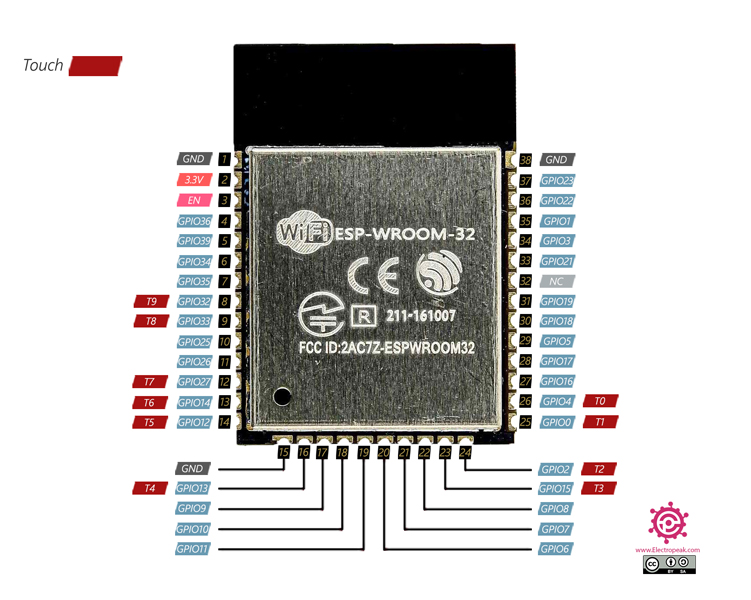
For more information go through the esp32 datasheet
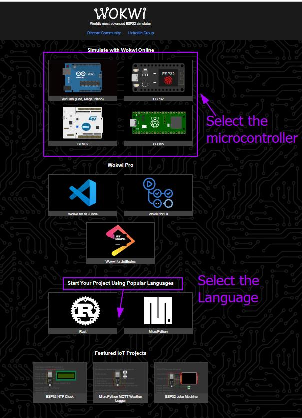
Wokwi is an online platform designed for simulating electronic circuits, particularly focusing on Arduino and ESP32 projects. I also find this tool a great for learning,designing circuits and protyping. Since I am using ESP 32 for my final project I am going to use esp32 in wokwi for the simulation.
LED blink
After goint through so many tutorial,Now I am little confident about programming.I edited on top of the code blinking led from the IDE. Here I added one more led, I want to control led1 with the command on1, off with off1 and to want to write on2 to turn on the led2,off2 to off the led.So I started editing the code using the esp32 as MCU in wokwi.
Here is the code that I edited on top of the blinking led
📌
     // Define the pin for the LEDs
      const int led1 = 18; // Use pin 13 for LED1
     const int led2 = 19;  // Use pin 9 for LED2

     void setup() {
      // Set the LED pins as output
      pinMode(led1, OUTPUT);
      pinMode(led2, OUTPUT);

    // Initialize serial communication at 9600 baud rate
     Serial.begin(9600);

     // Print a message to the Serial Monitor
     Serial.println("Enter 'on1' to turn the LED1 on or 'off1' to turn it off.");
     Serial.println("Enter 'on2' to turn the LED2 on or 'off2' to turn it off.");
     }

     void loop() {
     // Check if data is available to read from the Serial Monitor
     if (Serial.available() > 0) {
     // Read the incoming data as a string
     String command = Serial.readStringUntil('\n'); // Read until newline

     // Remove any leading/trailing whitespace
      command.trim();

     // Check the command and control the LEDs
      if (command == "on1") {
     digitalWrite(led1, HIGH); // Turn the LED1 on
     Serial.println("LED1 is ON");
     } else if (command == "off1") {
     digitalWrite(led1, LOW); // Turn the LED1 off
      Serial.println("LED1 is OFF");
      } else if (command == "on2") {
      digitalWrite(led2, HIGH); // Turn the LED2 on
       Serial.println("LED2 is ON");
      } else if (command == "off2") {
      digitalWrite(led2, LOW); // Turn the LED2 off
       Serial.println("LED2 is OFF");
      } else {
     // If the command is invalid, print an error message
      Serial.println("Invalid command. Enter 'on1', 'off1', 'on2', or 'off2'.");
           }
        }
      }
LCD Display with Blinking LEDS ESP32 in Wokwi
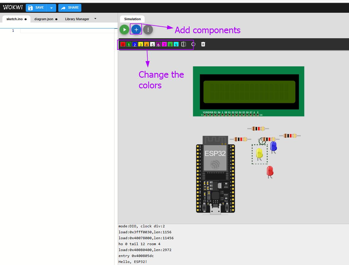
I refer the following datesheet for esp32 and LCD. Click here. After clicking on the link and it will open the page as shown in the image below.
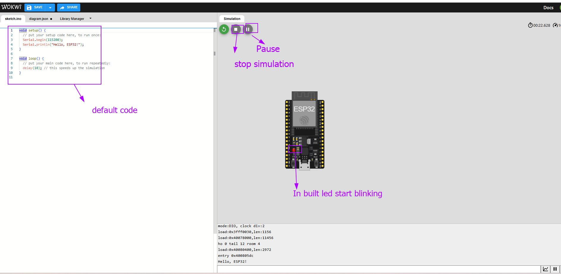
I added the Esp32 and checked whether in built esp32 led will blink or not. For that I used the default code and Clicked on simulation. The In built Led starts blinking.
Next I went by adding all the components. You can changed the colors of led and resistor value by clicking on the components.
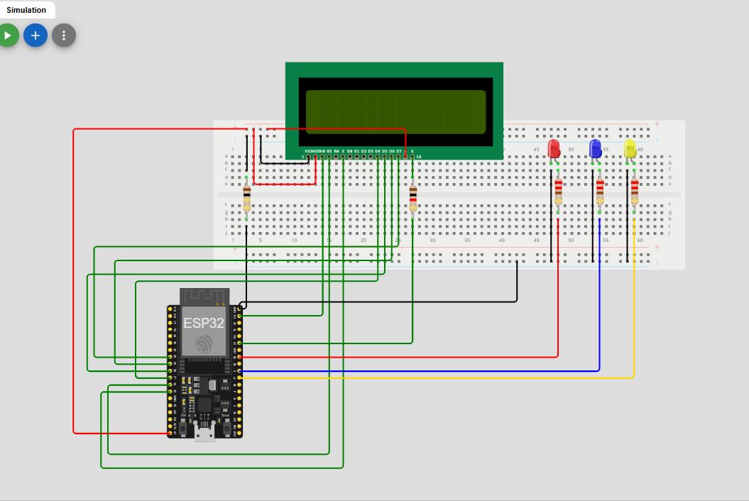
Then I made a connection for all the components. Checked whether my circuit is completed or not.
-
The screen is connected to the ESP32 (a small computer) using pins (14, 12, 27, 26, 25, 33). These pins help the ESP32 send messages to the screen.
-
The screen has a backlight (like the light in your room that helps you see things). The backlight is controlled by pin 21.When the program starts, the backlight turns on so you can see the words on the screen.
-
There are 3 colorful lights (LEDs) connected to pins 19, 5, and 17. These lights can turn on and off.Each light will turn on when a specific message is shown on the screen.
Next I went by running my script. I used the code by Nishan.Here I made some changes like changing the pins number.
📌
    #include <LiquidCrystal.h>
    // Define ESP32 GPIO pins for parallel LCD
    LiquidCrystal lcd(14, 12, 27, 26, 25, 33);  // LCD pins
    // ✅ Define LED GPIOs BEFORE setup()
    #define LED1 19
    #define LED2 5
    #define LED3 17
    #define BACKLIGHT 21
    void setup() {
    // Set LCD backlight pin as output
    pinMode(BACKLIGHT, OUTPUT);
    digitalWrite(BACKLIGHT, HIGH); // Turn ON backlight
    // Set LED pins as outputs and initialize them OFF
    pinMode(LED1, OUTPUT);
    pinMode(LED2, OUTPUT);
    pinMode(LED3, OUTPUT);
    digitalWrite(LED1, LOW);
digitalWrite(LED2, LOW);
digitalWrite(LED3, LOW);
// Initialize the LCD
lcd.begin(16, 2); // Assuming a 16x2 LCD
}
void loop() {
// Blink LED1 and display message
digitalWrite(LED1, HIGH);
lcd.setCursor(0, 0);
lcd.print("Hello Bir! ");
delay(1000);
digitalWrite(LED1, LOW);
lcd.clear();

// Blink LED2 and display message
digitalWrite(LED2, HIGH);
lcd.setCursor(0, 0);
lcd.print("Enjoy Learning");
delay(1000);
digitalWrite(LED2, LOW);
lcd.clear();

// Blink LED3 and display message
digitalWrite(LED3, HIGH);
lcd.setCursor(0, 0);
lcd.print("Esp32");
delay(1000);
digitalWrite(LED3, LOW);
lcd.clear();

delay(1000); // Pause before loop repeats
}
First Message:
-
Turn on the light connected to pin 19 (LED1).
-
Show the message “Hello Bir!” on the screen.
-
Wait for 1 second, then turn off the light and clear the screen.
-
Second Message:*
-
Turn on the light connected to pin 5 (LED2).
-
Show the message “Enjoy Learning” on the screen.
-
Wait for 1 second, then turn off the light and clear the screen.
Third Message:
-
Turn on the light connected to pin 17 (LED3).
-
Show the message “Esp32” on the screen.
-
Wait for 1 second, then turn off the light and clear the screen.
Blinking Leds using Micropython in Wokwi
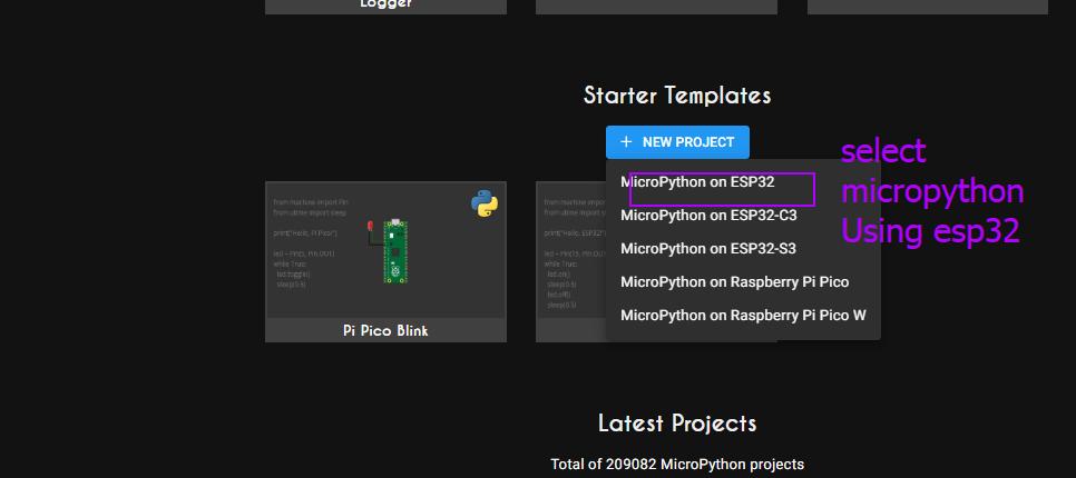
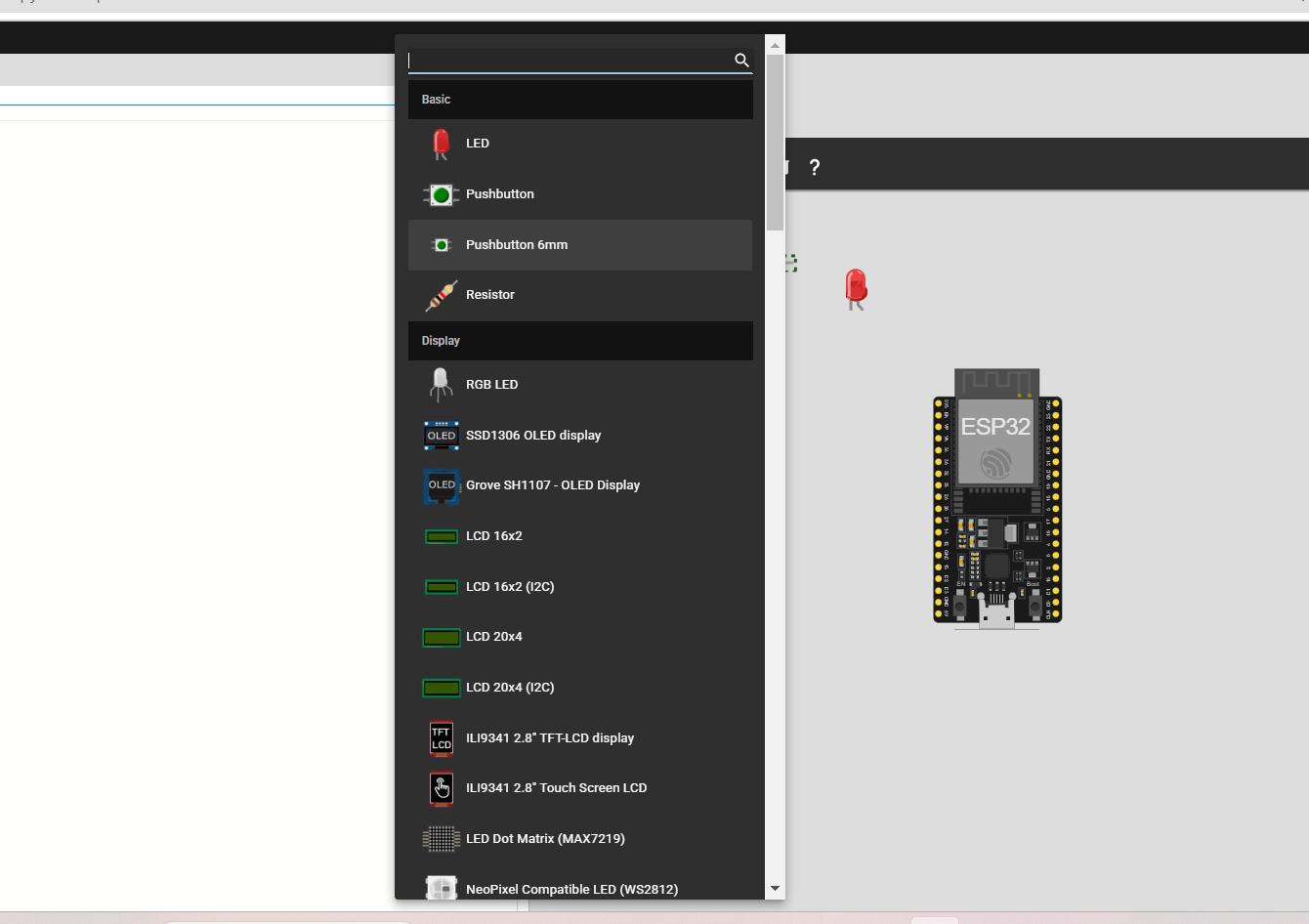
Firstly I open the wokwi in browser. I select the language as shown in the image below. Add the components as shown in second image.
I made the connections as shown in the image below.
-
led1 +ve pin is connected to Pin 15
-
Led2 +ve pin is connected to pin 18
-
Led3 +ve pin is connected to pin 19
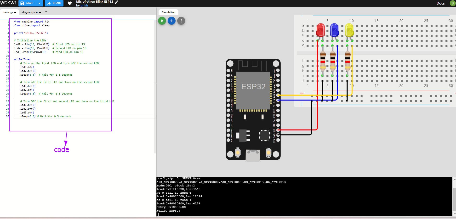
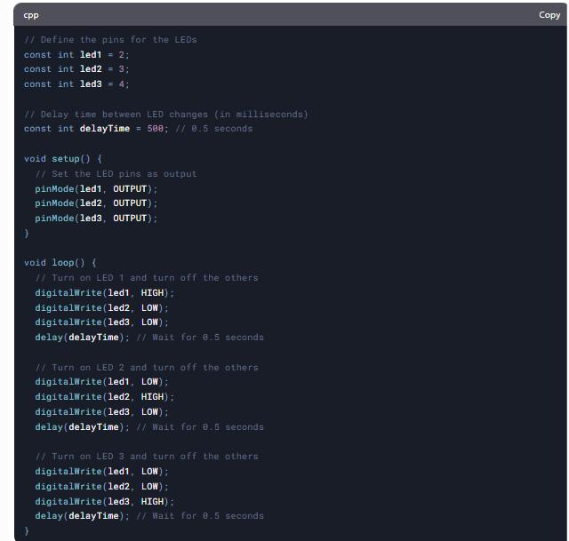
I generated code from chatgpt for the above simulation, hoewever,I want my code as in the message below. So I write the code led 2,3 off and wait for few seconds (code shown in the image above) by clicking on the simulation button. The code works✨.
Message 1
-
Turn on LED1 (the first light).
-
Turn off LED2 (the second light).
-
Wait for 0.5 seconds (half a second).
Message 2
-
Turn off LED1 (the first light).
-
Turn on LED2 (the second light).
-
Wait for 0.5 seconds.
Message 3
-
Turn off LED1 and LED2 (both the first and second lights).
-
Turn on LED3 (the third light).
-
Wait for 0.5 seconds.
Getting started with Thonny
Thonny is an integrated development environment (IDE) specifically designed for beginners in Python programming.
Download and install Thonny
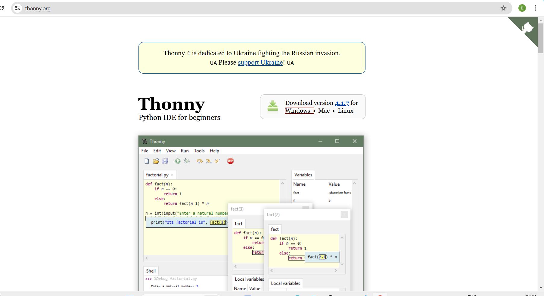
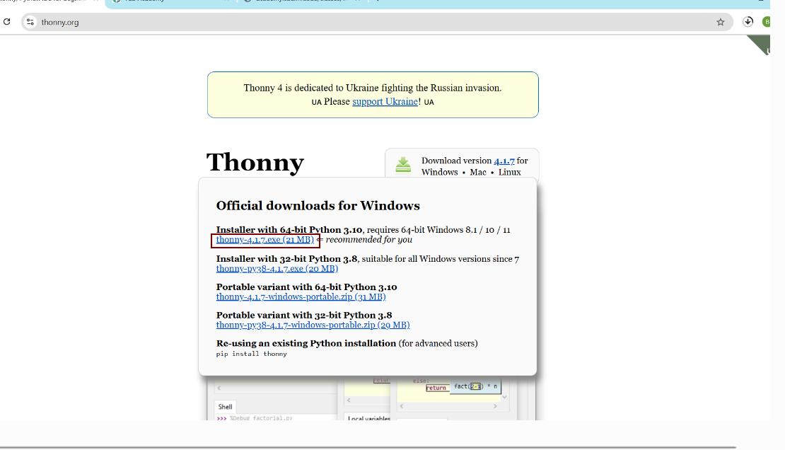
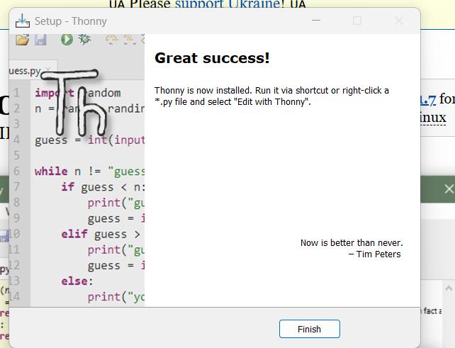
Go to browser and click on the link above and download. Thonny was installed to my laptop. Open the Thonny IDE after installation.
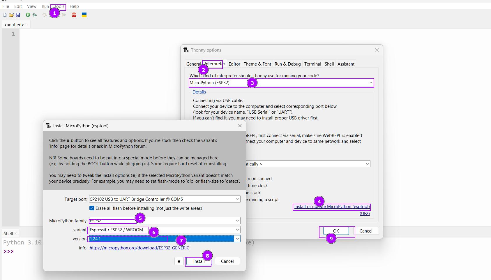
Installing Micropython on esp 32
- Connect the Esp 32 using the cable port. Open Thonny and go to Tools > Options> select micro python (esp32)> click on Install or update firmware. Select the correct esp32 board from the list and choose the latest firmware update and click on intsall. Or follow the image as shown below.
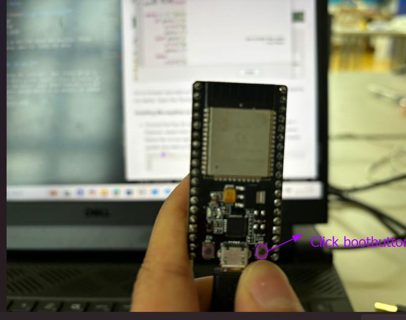
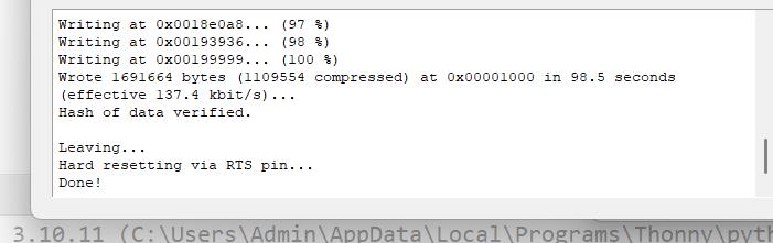
After clicking on intall. Press the boot button of esp32 as shown in the image below.
Now the I have successfully install micropython.
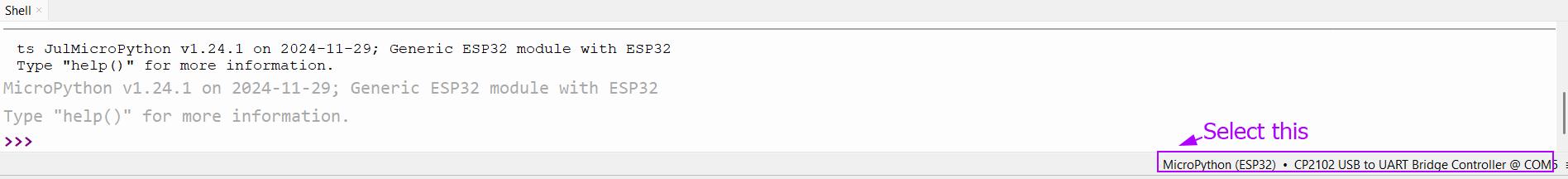
Connecting Esp32 to Thonny
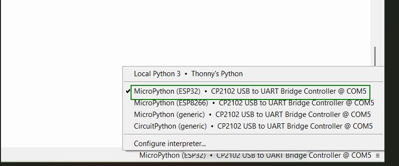
Open Thonny, at bottom shell window select ESP32 Micropython and also select the correct COM.
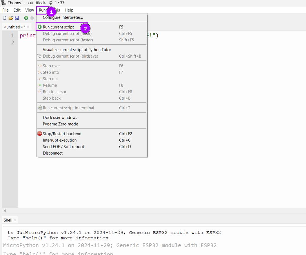
Running my first Micropython script
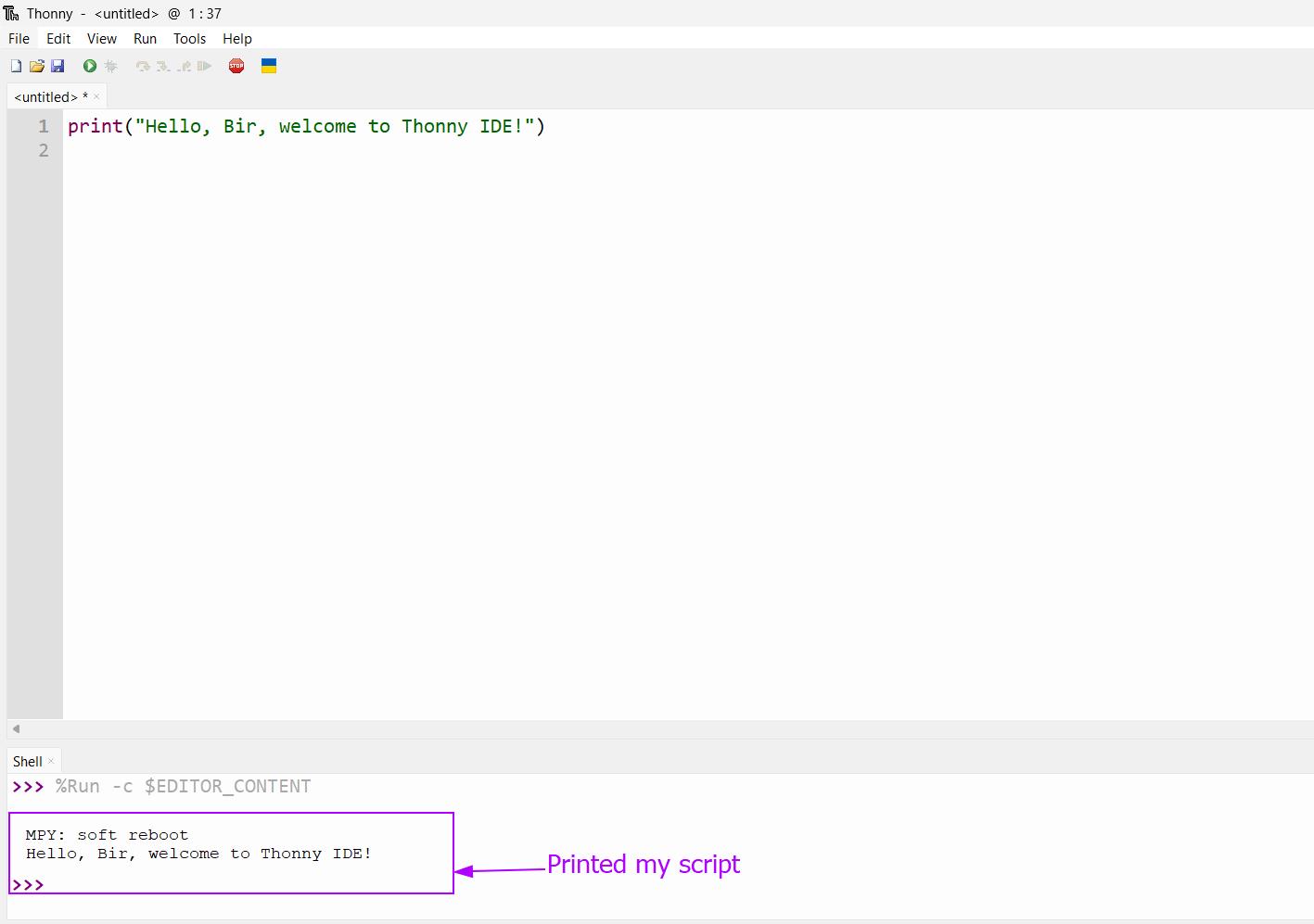
Open Thonny > In the editor> write the simple test script like > click run. It will print your script in the shell.
print("Hello, Bir, welcome to Thonny!")
Next I did with blinking inbuilt led of esp32. Open Thonny >In editor > used the code > click on run. The Led start blinking as shwon in the video below. I used the code Chatgpt.
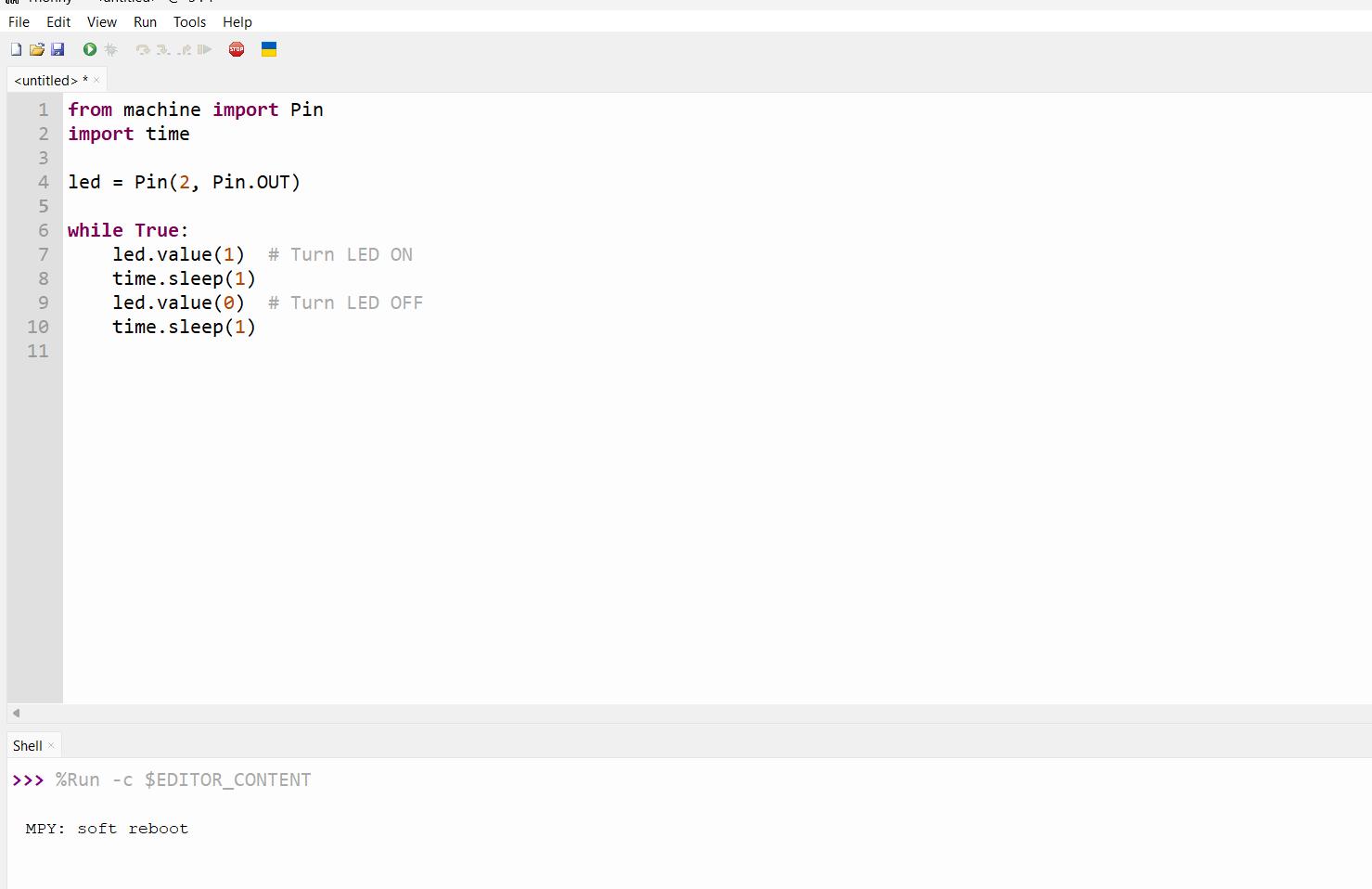
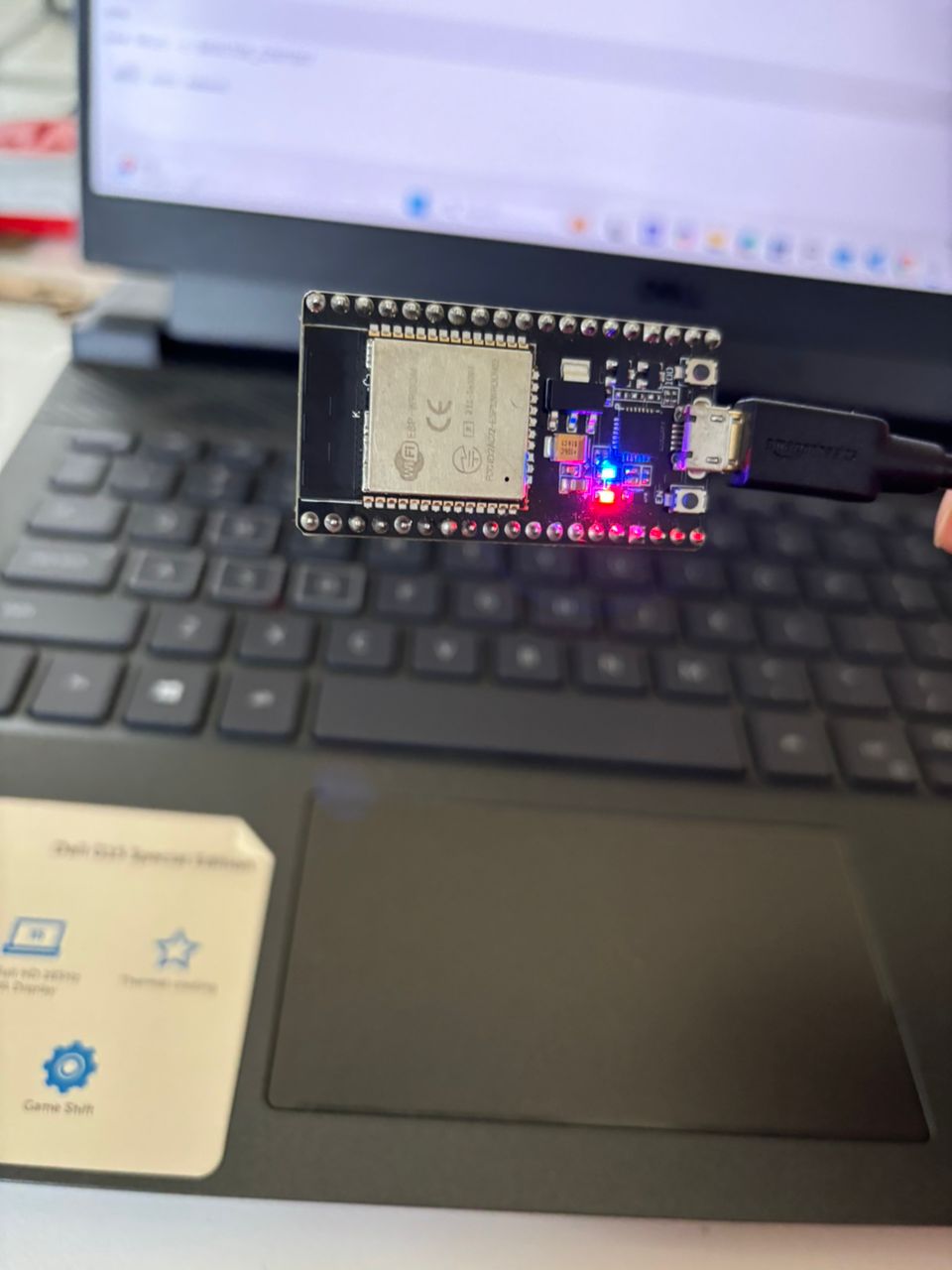
Image above shows that the led starts blinks when I click on the run script.
WiFi AP-Based LED Control via Web Browse
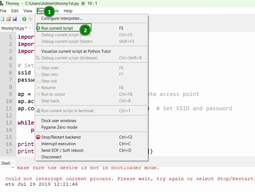
I opened Thonny IDE, In editor, I used code by wifiaccess code. I use chatgpt to convert the code language to micropython. I made sure that I am using the correct COM and then Run my script by clicking on the run script.
The code I used is given below.
📌
  import network
  import socket
  import machine

  # Set up the access point (AP) mode
   ssid = "yourAP"
   password = "yourpassword"

   ap = network.WLAN(network.AP_IF)  # Create access point
   ap.active(True)  # Activate it
   ap.config(essid=ssid, password=password)  # Set SSID and password

   while not ap.active():
   pass

   print("Access Point active")
   print("AP IP address:", ap.ifconfig()[0])

   # Set up LED (GPIO 18 for LED on many ESP32 boards)
   led = machine.Pin(18, machine.Pin.OUT)

    # Create a socket server
   server_socket = socket.socket(socket.AF_INET, socket.SOCK_STREAM)
   server_socket.bind(("0.0.0.0", 80))  # Listen on all interfaces, port 80
   server_socket.listen(5)

   print("Server started")

    while True:
   client, addr = server_socket.accept()
   print("New client connected:", addr)

  request = client.recv(1024).decode()
  print(request)

   # Check for URL path in request
   if "GET /H" in request:
    led.value(1)  # Turn LED on
   elif "GET /L" in request:
    led.value(0)  # Turn LED off

    # Send HTTP response
   response = """\
  HTTP/1.1 200 OK
   Content-Type: text/html

  <html>
   <head><title>ESP32 LED Control</title></head>
  <body>
   <h2>ESP32 Web Server</h2>
   <p>Click <a href='/H'>here</a> to turn ON the LED.</p>
  <p>Click <a href='/L'>here</a> to turn OFF the LED.</p>
  </body>
   </html>
   """
   client.send(response.encode())
  client.close()
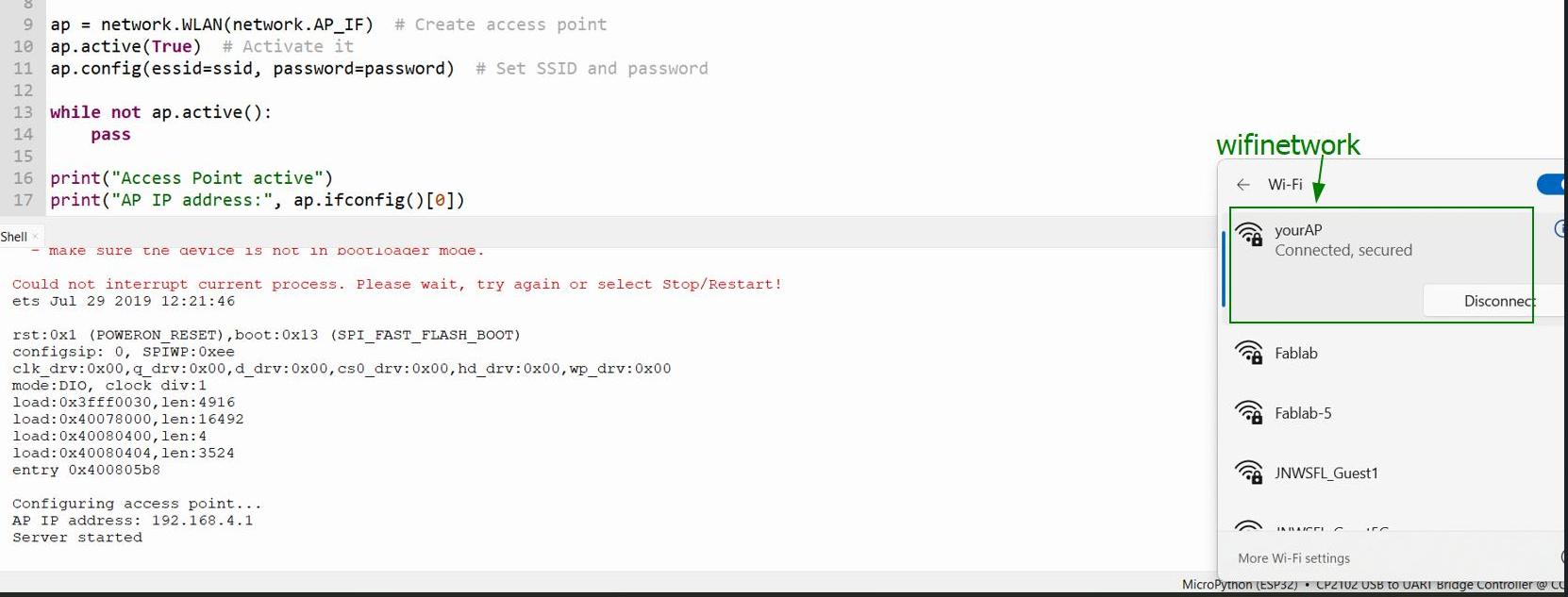
Upon completetion, I look for wifi name “YourAP” and successfully connected it.
I copied the IP address 192.168.4.1 and pasted in the browser. The command LED on and off appears as shown in the image below.
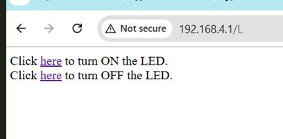
✨ Done! I can control Led from the browser.!:rocket:
Arduino Uno
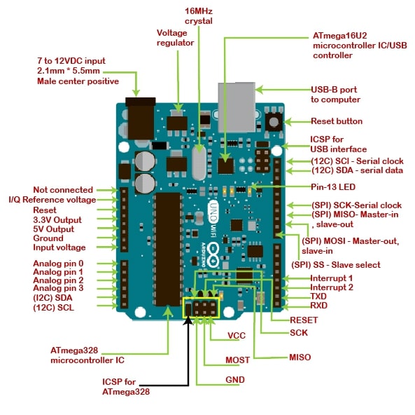
Arduino Uno is microcontroller that uses the micro chip ATmega328P. It has 14 digital input/output pins (six of which can be used as PWM outputs), six analog inputs, and a 16MHz quartz crystal.
I refer this datasheet to learn about the Arduino and Arduino chip ATmega328/P
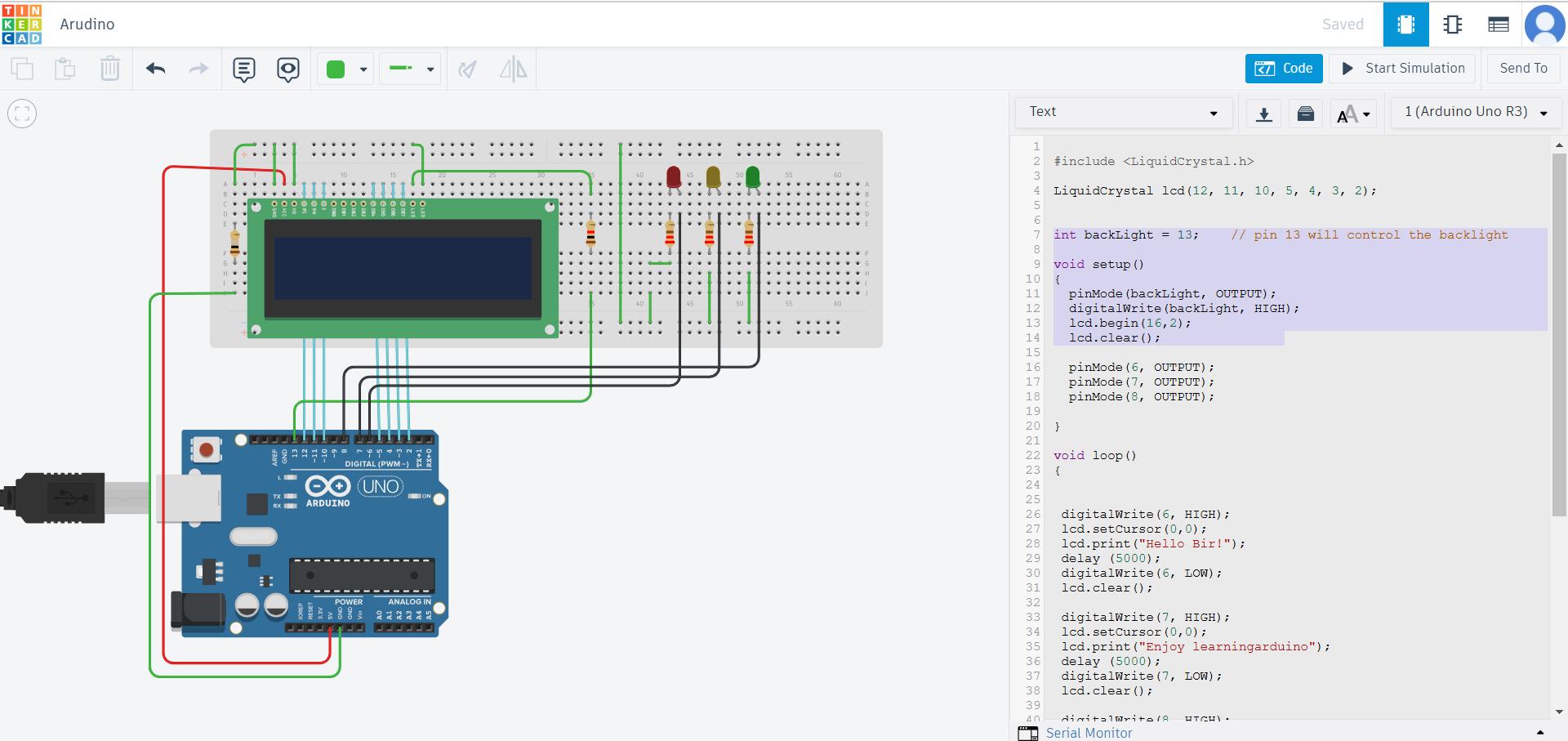
LCD Display with Blinking LEDs using Arduino on Tinkercad
Tinkercad is free online platfrom where we can do the 3d designing, circuits, coding and simulation.
I refer the Arduino datasheet to understand how it works and to know about the pinout functions.
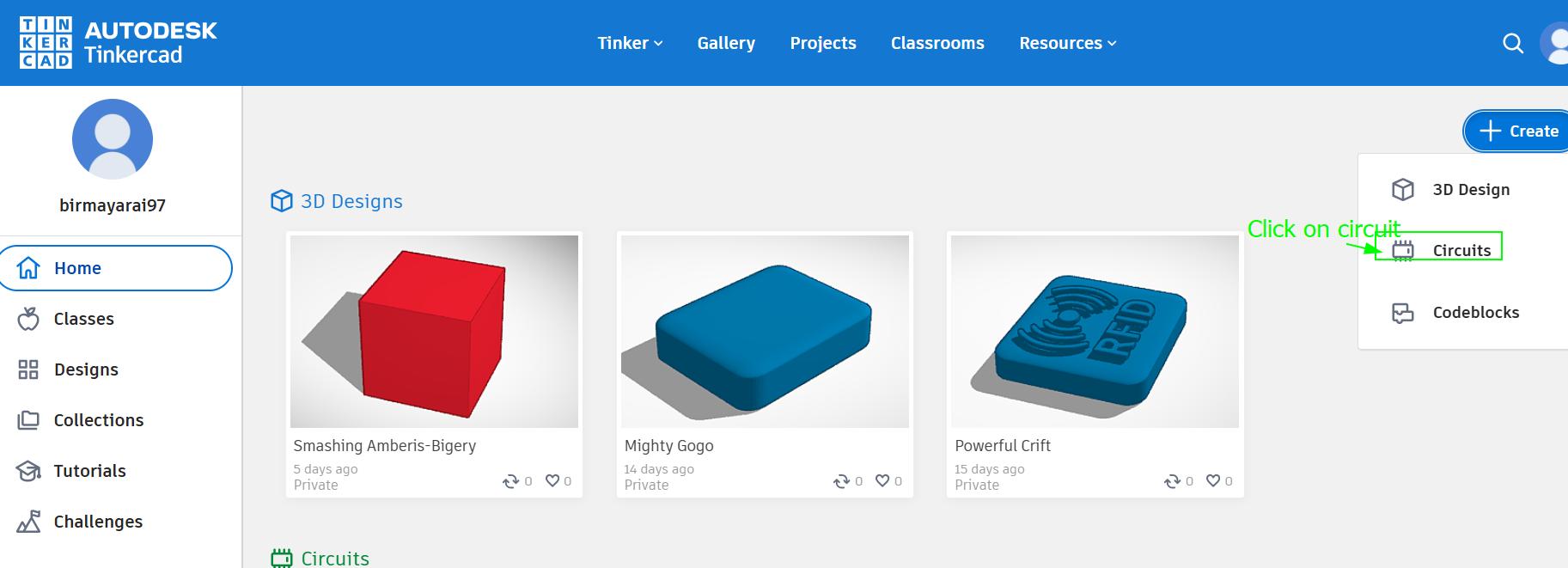
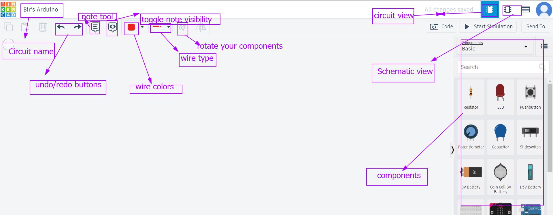
Go to Tinkercad account and create a new account if you dont have one.Once you login click on the circuts on the left side of the page and click on new circuits to start a new project. The second image below some of the interfaces you will use while doing your circuits project.
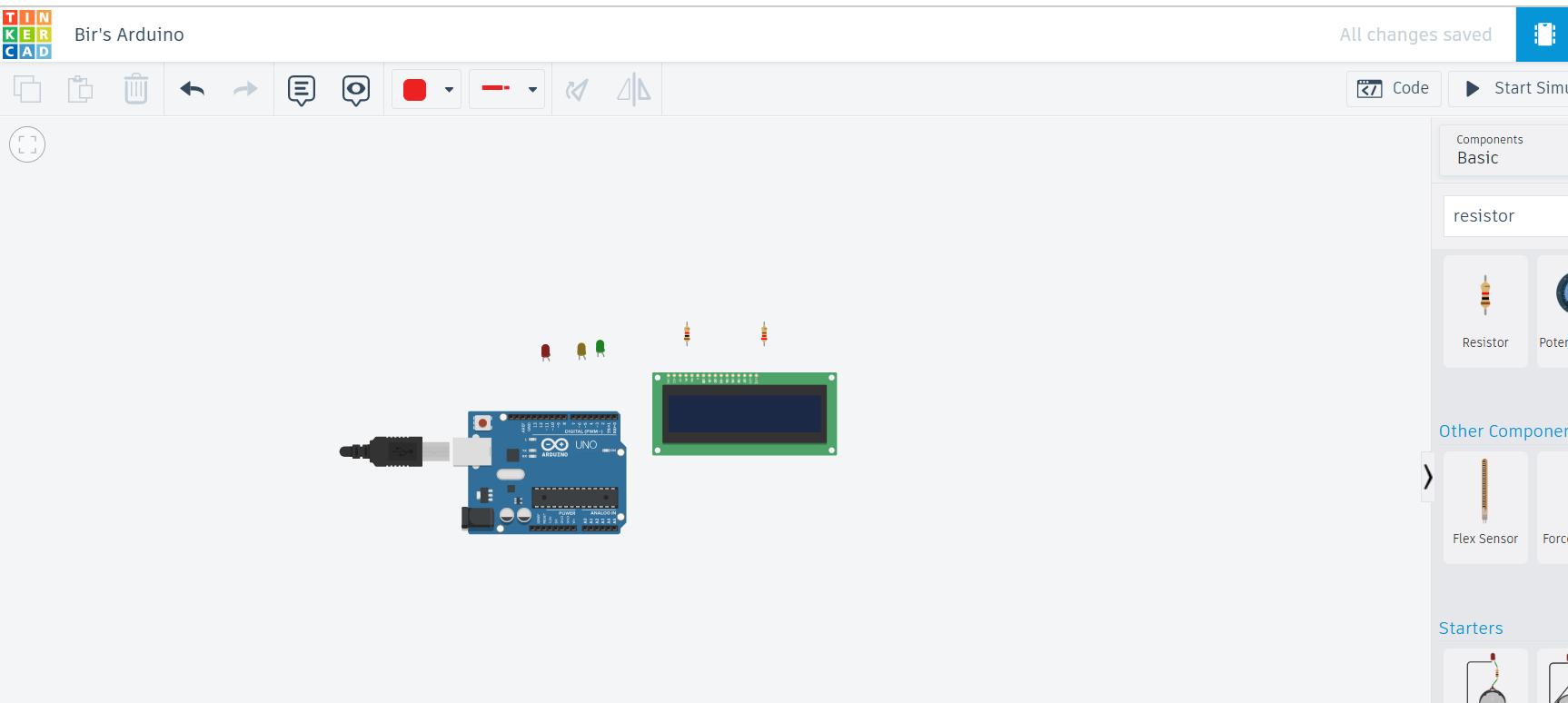
Next I went by adding a wire to complete my circuit connections.
-
You can add the can the components to desgin the circuits. Here I am using Arduino Uno, lcd,resistor and led to design my circuits.
-
The LCD is connected to the Arduino using pins (12, 11, 10, 5, 4, 3, 2). These pins help the Arduino send messages to the screen.
-
The screen has a backlight (like the light in your room that helps you see things). The backlight is controlled by pin 13.
-
There are 3 lights (LEDs) connected to pins 6, 7, and 8. These lights can turn on and off.Each light will turn on when a specific message is shown on the screen. I used the code given below to simulate my circuit. I used code by [Nishan] (https://www.tinkercad.com/things/ceAEfbIE0Yd-arduino-lcd-and-led-)
📌
         #include <LiquidCrystal.h>
          LiquidCrystal lcd(12, 11, 10, 5, 4, 3, 2);

          int backLight = 13;    // pin 13 will control the backlight

         void setup()
         {
          pinMode(backLight, OUTPUT);
          digitalWrite(backLight, HIGH);
          lcd.begin(16,2);
           lcd.clear();
           pinMode(6, OUTPUT);
           pinMode(7, OUTPUT);
           pinMode(8, OUTPUT);
           }
           void loop()
           {
           digitalWrite(6, HIGH);
          lcd.setCursor(0,0);
          lcd.print("Hello Bir!");
          delay (5000);
          digitalWrite(6, LOW);
          lcd.clear();
          digitalWrite(7, HIGH);
          lcd.setCursor(0,0);
          lcd.print("Enjoy learningarduino");
          delay (5000);
          digitalWrite(7, LOW);
          lcd.clear();
          digitalWrite(8, HIGH);
          lcd.setCursor(0,0);
          lcd.print("keep tinkering");
          delay (5000);
          digitalWrite(8, LOW);
          lcd.clear();
          delay (1000);
          }
First Message:
-
Turn on the light connected to pin 6.
-
Show the message “Hello Bir!” on the screen.
-
Wait for 5 seconds, then turn off the light and clear the screen.
Second message:
-
Turn on the light connected to pin 7.
-
Show the message “Enjoy learning Arduino” on the screen.
-
Wait for 5 seconds, then turn off the light and clear the screen.
Third Message:
-
Turn on the light connected to pin 8.
-
Show the message “keep tinkering” on the screen.
-
Wait for 5 seconds, then turn off the light and clear the screen.
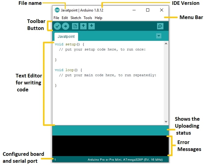
Getting started with Arduino IDE
The Arduino IDE is an open-source software, which is used to write and upload code to the Arduino boards. The IDE application is suitable for different operating systems such as Windows, Mac OS X, and Linux. It supports the programming languages C and C++.
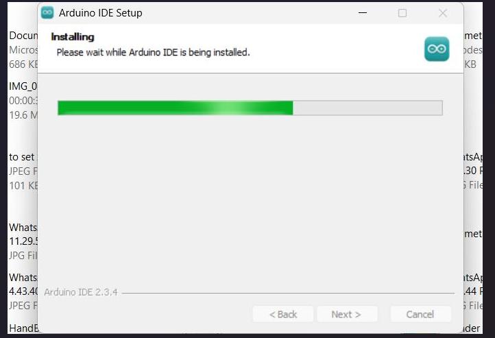
Download the Arduino IDE software and successfully installed on my laptop.
When you open the Arduino ide it will appears as image below:
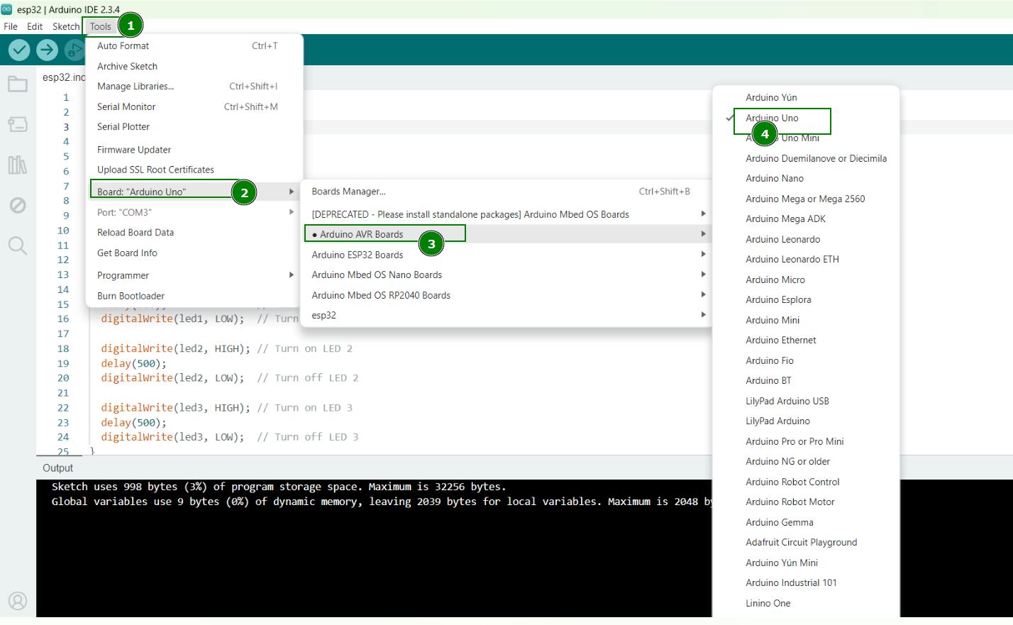
I went by adding board from the Url.
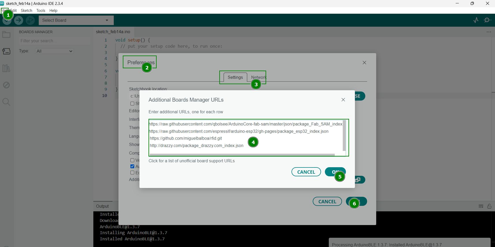
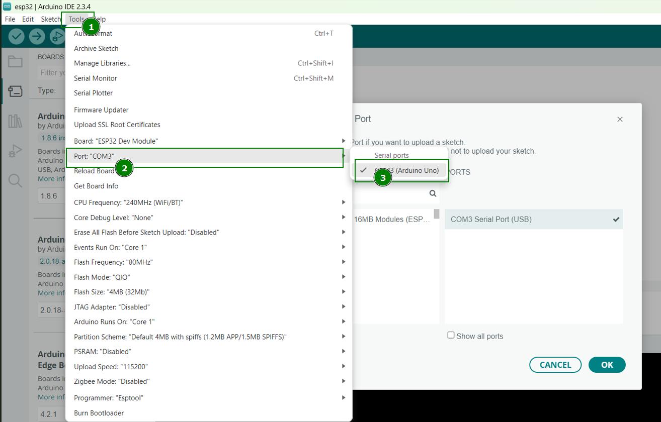
Next I connect my Arduino to my lapto using USB port. Following are the steps that I followed to add board and USB
I wrote a code using Arduino IDE, this code will make three led blink one after another.Open the Arduino IDE After compiling the code, I uploaded it to the Arduino Uno board.Since I already did simulation using ESP32 in wowki.I just made few changes in the arduino code by changing the pin and adding on serial monitor.
The prompt that I used
I am making a circuit where, I have three led and I want to led to glows one after another. I need the program
The code that I generated from chatgpt
I edited the code generated from chatgpt as per my requirement.
📌
 // Define LED pins
  const int led1 = 8;
  const int led2 = 7;
  const int led3 = 4;

 void setup() {
// Initialize LED pins as output
pinMode(led1, OUTPUT);
pinMode(led2, OUTPUT);
pinMode(led3, OUTPUT);

// Start Serial communication
Serial.begin(9600);
}

 void loop() {
// Turn on LED1 and print status
digitalWrite(led1, HIGH);
Serial.println("LED 1 is ON");
delay(500);
digitalWrite(led1, LOW);
Serial.println("LED 1 is OFF");
delay(500);

// Turn on LED2 and print status
digitalWrite(led2, HIGH);
Serial.println("LED 2 is ON");
delay(500);
digitalWrite(led2, LOW);
Serial.println("LED 2 is OFF");
delay(500);

// Turn on LED3 and print status
digitalWrite(led3, HIGH);
Serial.println("LED 3 is ON");
delay(500);
digitalWrite(led3, LOW);
Serial.println("LED 3 is OFF");
delay(500);
}
Files :file_folder:
Code files are attached below: