Week 09. Input Devices
Adafruit LSM303AGR
The board that I produced last week wasn't up to the task, so I fell back to bread board.
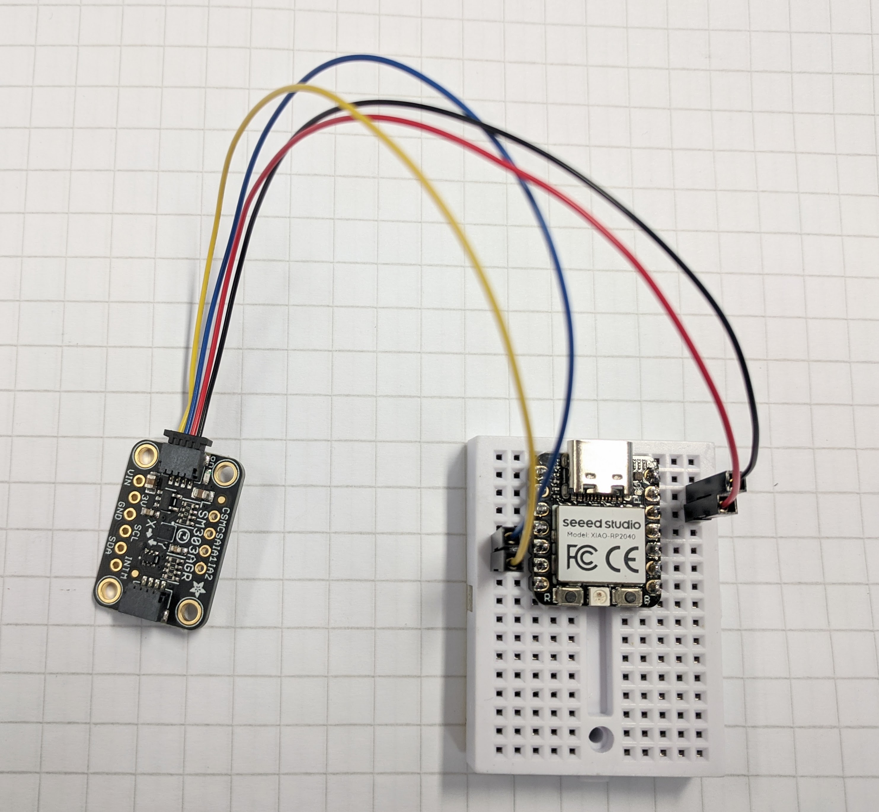
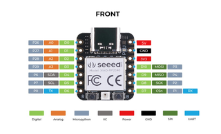
Connecting LSM303AGR to XIAO RP2040 with JST to pin connector.
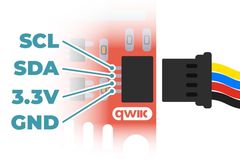
Note the QUIIC connector color convention for the wires.
- Yellow: SDL
- Blue: SDA
- Red: 3.3V
- Black: ground
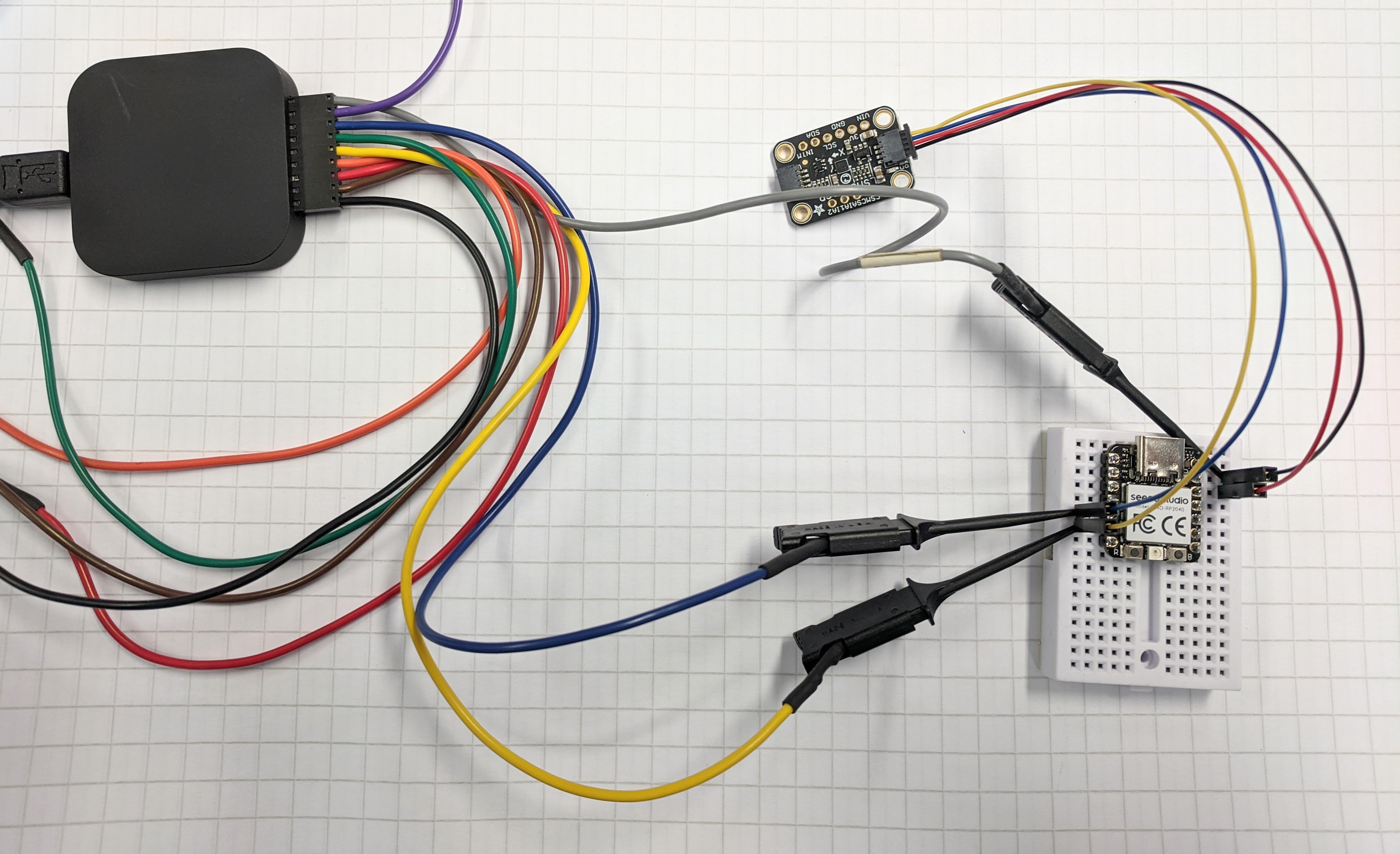
Probing the I2C connection with the Saleae. I followed the color convention for blue and yellow wires.
Update with own board
Once I had my own circuit board working after week 10 I repeated the exercise, and got the same result.
Using the magsensor.ino example code, which reads the magnetometer sensor every 100ms. It is loaded on the XIAO RP2040.
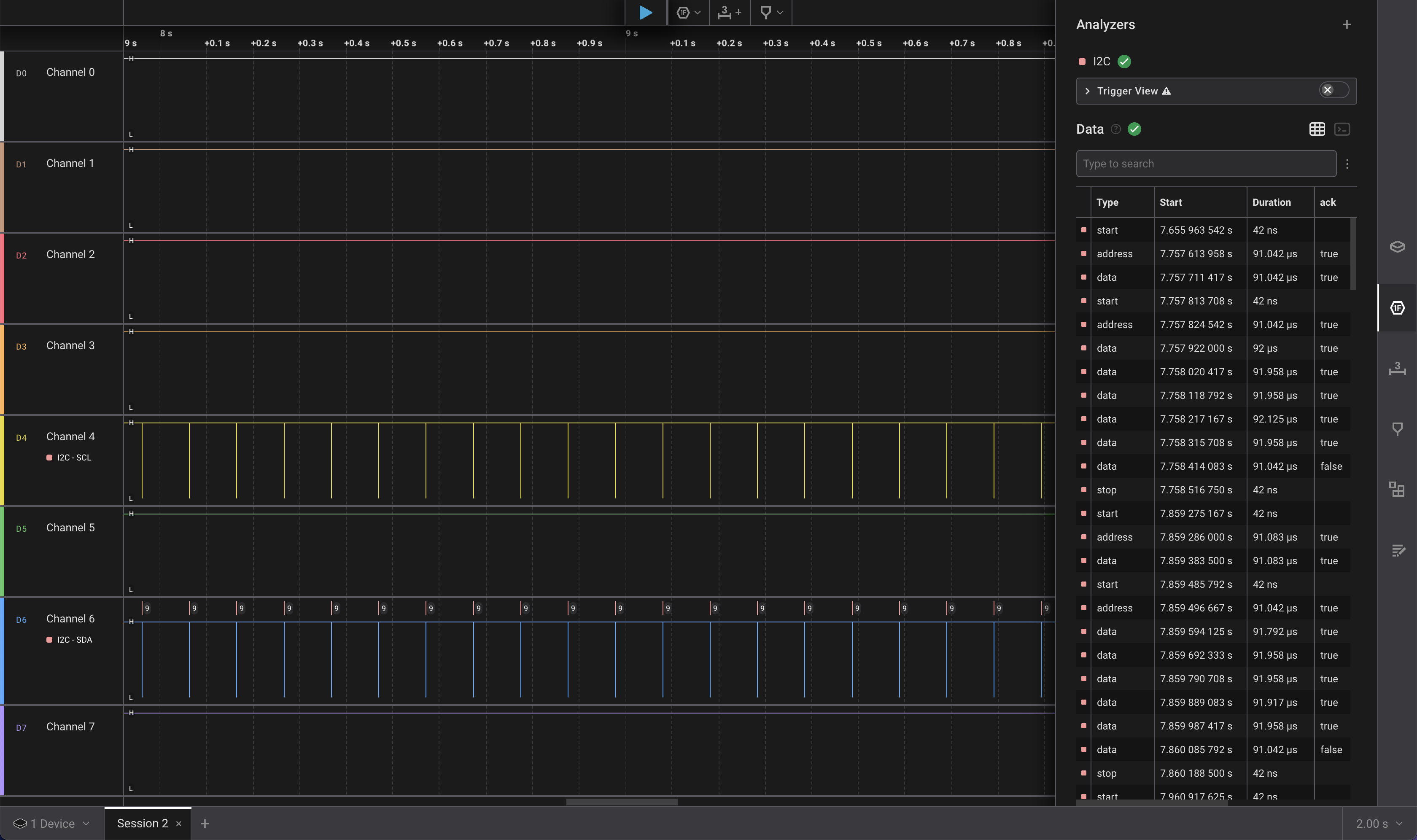
2s view. You can see the 10 times per second that data is communicated.
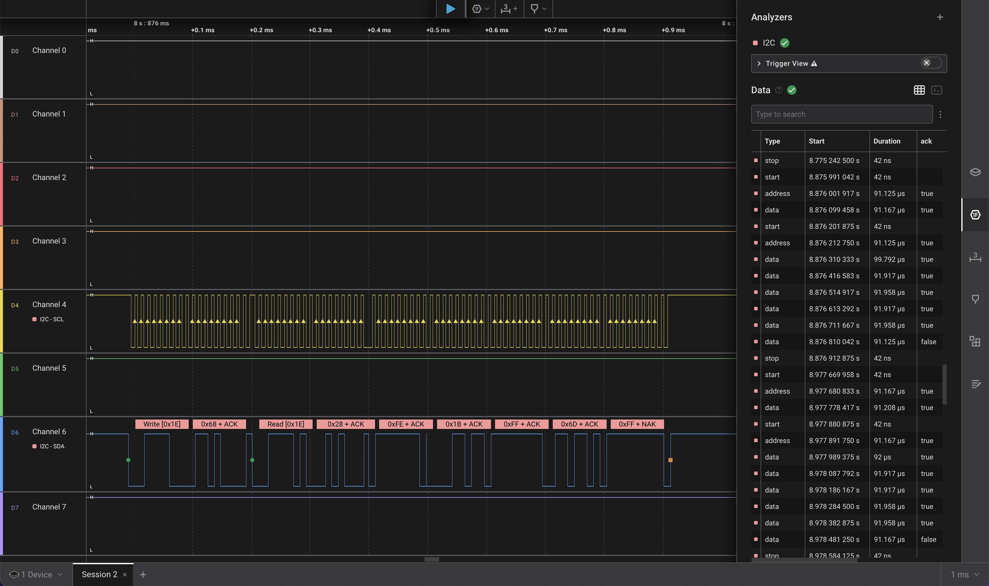
1ms view. Zooming into 1 report of the sensor reading.
X: -55.35  Y: -30.60  Z: -30.75  uT
X: -54.60  Y: -30.60  Z: -30.75  uT
X: -55.50  Y: -30.15  Z: -31.20  uT
This program outputs messages like this in the Arduino serial monitor.
Next steps
- Characterize power requirements and SPI control of addressable LED strip.
- Make circuit board that can support battery, RP2040, sensor, and LED power and control.
- Connect mag sensor and do programming to make LED colors react to orientation changes.
- Continue tactile labyrinth prototyping.
Reference
- Group work
- I2C
- QWIIC – I2C with 4-pin JST connectors.
- XIAO RP2040
- Adafruit LSM303 – accelerometer and magnetometer.
- Saleae logic analyzer, using I2C.
- 6 axis accelerometer + gyroscope fusion
- ← Previous
Week 08. Electronics Production - Next →
Week 10. Output Devices