Week 10. Output Devices
Group work
Characterizing the power consumption of my addressable RBG LED rope.
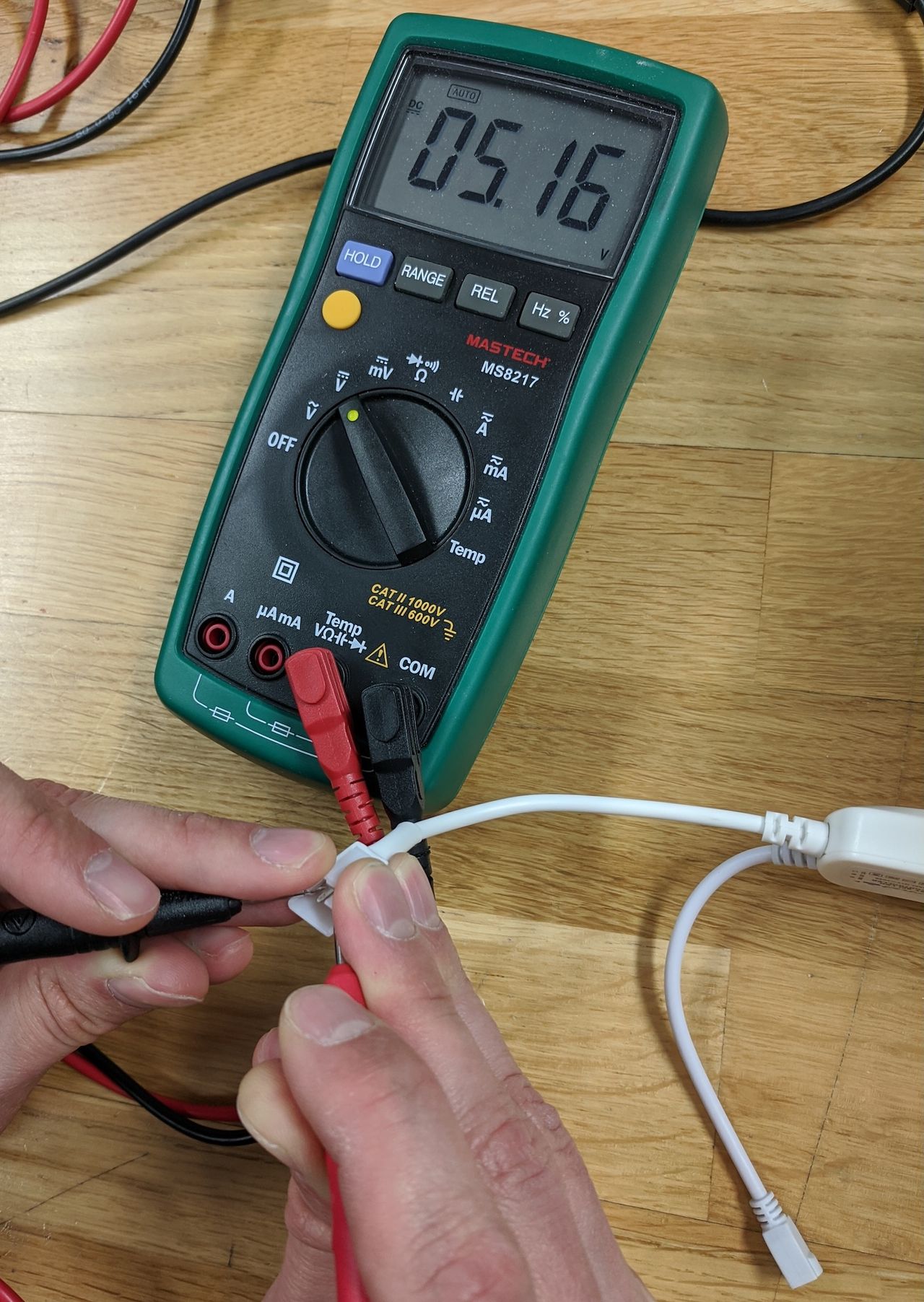
LED rope with battery bank and supplied controller, power meter showing 5 volts. I did not make this board; it came with the LED rope.
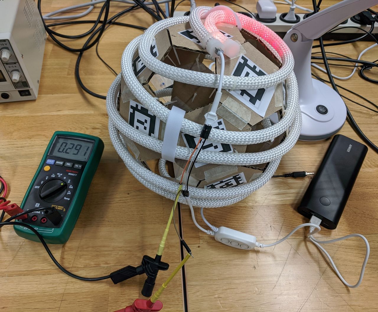
With only a some of the rope lit up, the power meter shows 0.3 amps.
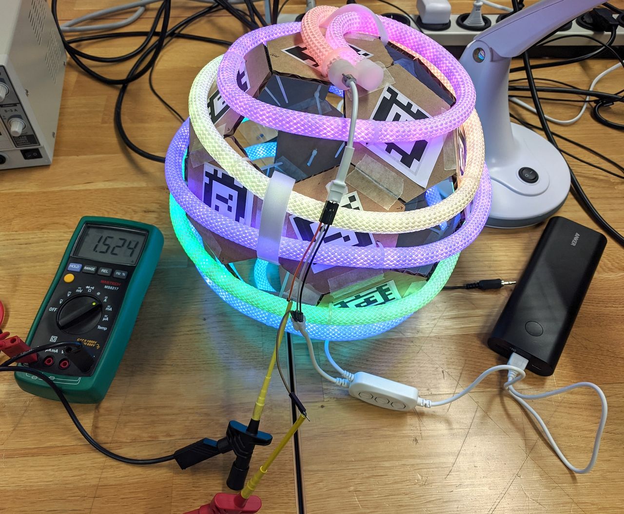
With the rope fully lit up, the the power meter shows 1.5 amps.
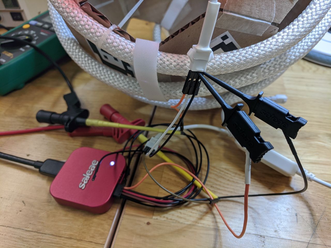
Setup to probe the data line with the Salaea and supplied controller.
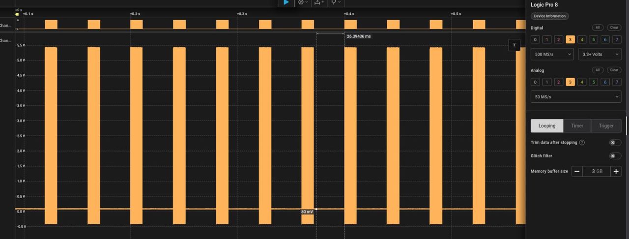
Probe UI showing 5v data signals.
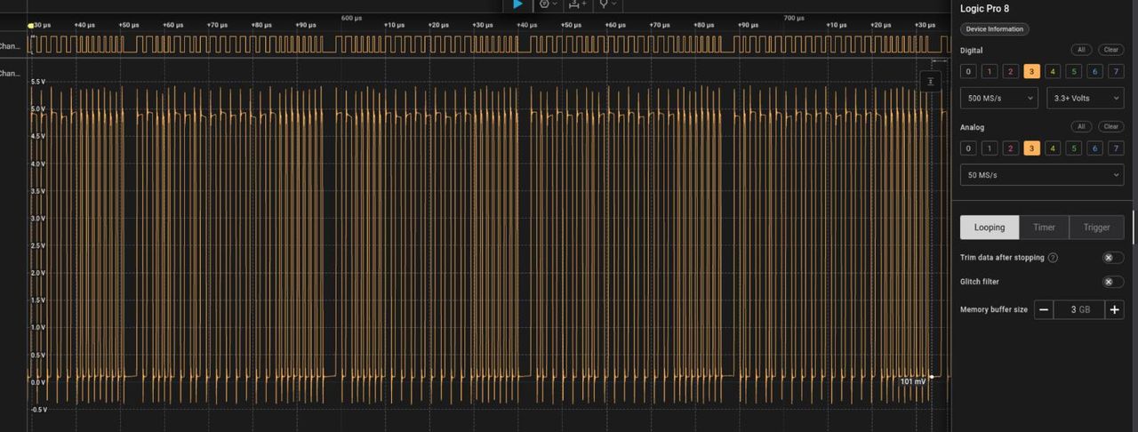
Probe UI zoomed in to a data signal.
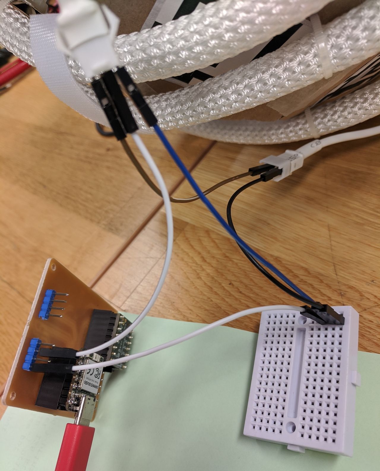
Using an existing dev board with a level shifter. I did not make this board, it was available in the lab for group work. I did program it to test the Arduino libraries that I want to use on the XIAO. FastLED working!
Circuit fo_v3
Since the XIAO RP2040 data pins have 3.3v and the LED rope data line needs 5v, I knew that my breakout board needed a level shifter. We added a LevelShifter_Texas_TXB0104DR_SOIC-14 from the fab inventory. We also added a power-only USB connector.
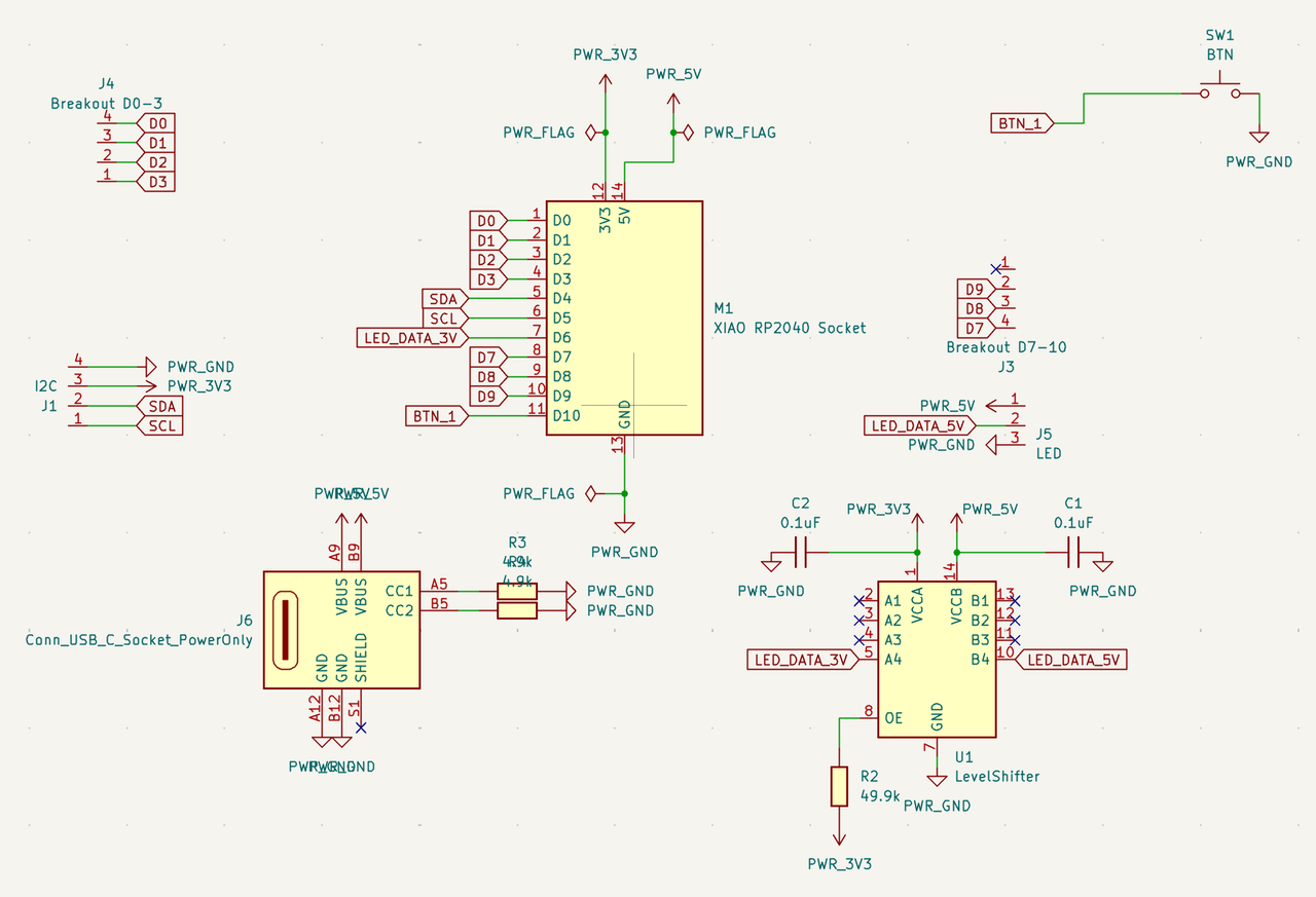
fo_v3 KiCad schematic.
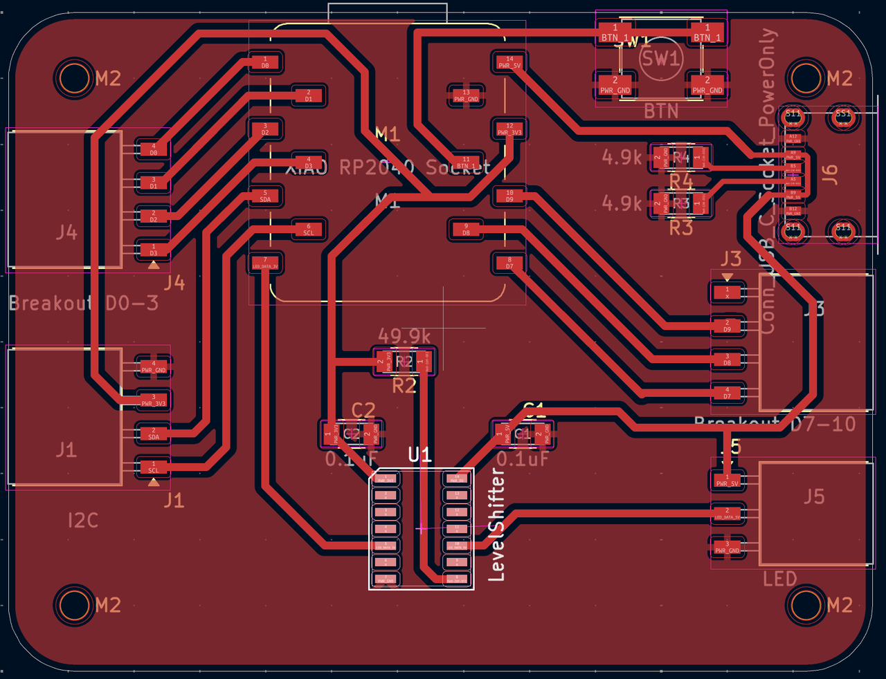
PCB design. I have to say that the routing is quite satisfying and I can see it being addictive.
📝 Capacitors should be as close as possible to the chip.
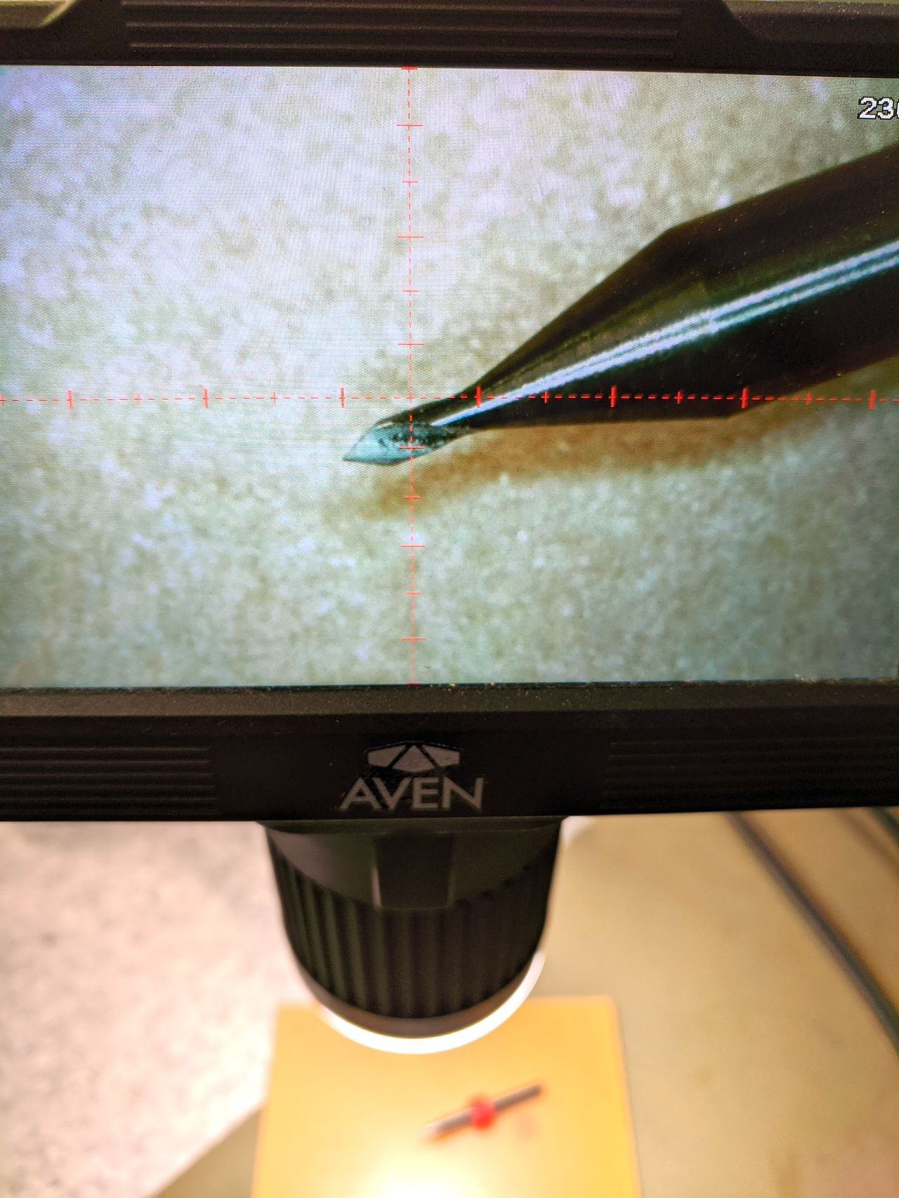
The USB-C power breakout requires a 0.3mm clearance. We have 0.3mm routing bits, but the Bungard mill started breaking them. After breaking a few, we switched to a v-bit, which worked.
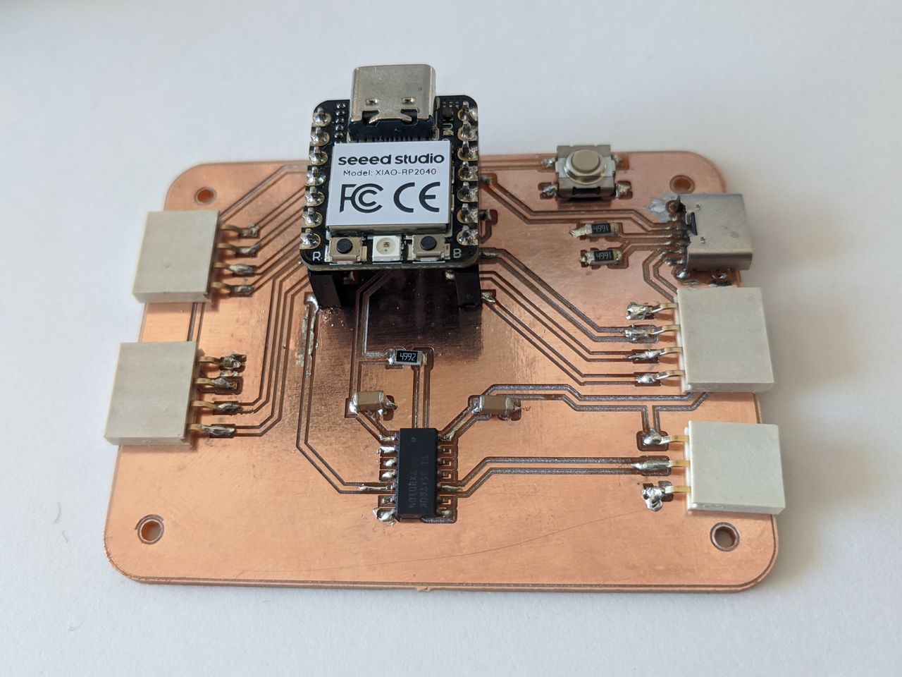
fo_v3 circuit assembled. Better than last time! I'm tempted to encase it in hot glue.
Big thanks to Kris' soldering tips videos. The key tip for me was the surface mount chip order of operations:
- Put a little solder on one corner pad.
- Place the chip with tweezers, make sure the rest of the feet are aligned.
- Melt the one foot into the solder blob, again make sure the rest of the feet are aligned.
- Solder the opposite corner foot and pad.
- Do the rest. Go slow.
📝 The level shifter is symmetrical and the data sheet didn't give a clue as to which way the text is printed. The printed dot on the top is closest to pin 1.
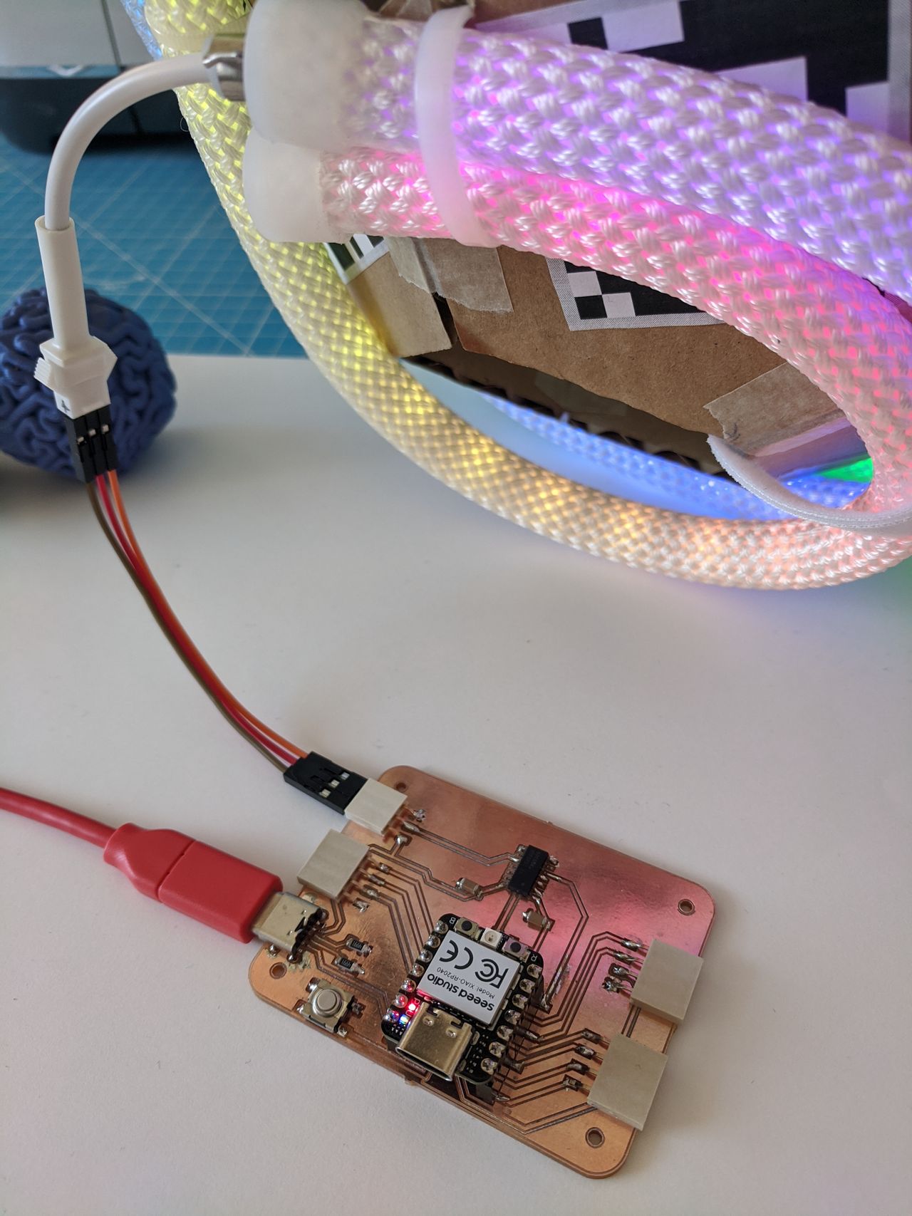
XIAO to LED rope working on fo_v3 board. 😅
Next steps
- Make a light animation to go from 0 → 250 with full brigtness white, to see the real max amps of the LED rope.
- Connect 6dof sensor and start programming lights reacting the the ball movement.
- Iterate on the electronics enclosure and light ball design. 🌀
Files
- kicad_fo_v3.zip
- HelloLEDRopeColorPalette.ino – this was a FastLED example program with configuration changes to match my LED rope and board.
- ← Previous
Week 09. Input Devices - Next →
Week 11. Networking and Communications