Week 09
Output Devices
Brief Overview
In this week of FabAcademy, my individual assignment involved creating and implementing a program for a microcontroller development board that I made in Electronics production week. This program facilitates interaction with local input/output devices and communication with remote devices, utilizing both wired and wireless connections. As an extra credit endeavor, I incorporated different programming languages and development environments, and further expanded the project by connecting external components to the board. Concurrently, our group assignment revolved around an extensive exploration of the microcontroller's datasheet, allowing us to compare its performance and development workflows with other architectures. This comprehensive approach not only deepened my understanding of embedded programming but also provided valuable insights into the diverse landscape of microcontroller architectures and their applications, aligning seamlessly with the goals of FabAcademy.
My Heroshot for this Week
 |
 |
 |
 |
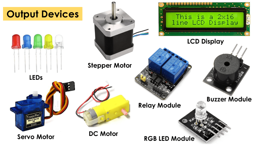
Introduction to Output Devices:
Definition:
Output devices are hardware components that convey information from a computer or electronic device to the user or to other systems. Output devices in the realm of electronics play a vital role in conveying processed information to users in various forms. These devices are responsible for converting digital or analog signals into perceptible outputs, thereby facilitating interaction between humans and electronic systems. Common examples include displays like monitors, screens, and projectors which visually present data, speakers and headphones which output audio signals, and printers which produce hard copies of digital documents. Output devices are indispensable components across numerous electronic applications, ranging from personal computing to industrial automation, enriching user experience and enabling effective communication of processed information.
Purpose:
They present processed data to users in various forms such as text, images, sounds, or physical motion.
Examples:
Display, speakers, motors, LEDs, etc.
Output Devices in my assignment
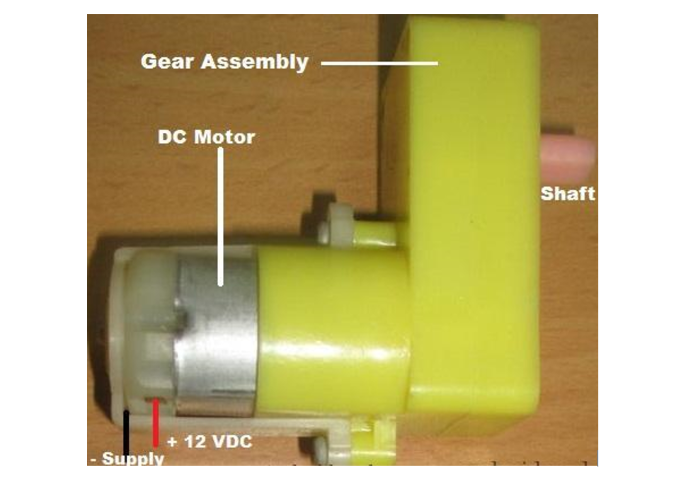
BO Motor:-
Brushed DC (Direct Current) motors operate based on the attraction and repulsion of magnets.
Bo motor (Battery Operated) is a lightweight DC geared motor that produces high torque and rpm at low voltages. A bo motor with varying rated speeds is available here. When powered by a single Li-Ion cell, this motor can reach speeds of around 200 rpm. Excellent for battery-powered lightweight robots. This Bo Motor can be interfaced to a motor wheel and chassis, which is perfect to make a DIY mobile robot car.
BO Geared DC Motor typically has a metal gearbox with gears made of high-quality materials such as steel, brass, or bronze. The gearbox is usually attached to the motor shaft and can provide gear ratios ranging from 1:10 to 1:1000. The BO Geared DC Motor is available in various sizes and power ratings, depending on the specific application requirements. They are often used in applications where precise speed control and high torque output are required, such as in robotics, automation, and machinery. These motors are usually controlled using a motor driver, which provides the necessary voltage and current to drive the motor. They can be controlled using various types of motor drivers such as H-bridge or PWM (Pulse Width Modulation) motor controllers.
Dc motor converts electrical energy into mechanical energy.
DC MOTOR concept is where gears reduce the speed of the vehicle but increase its torque is known as gear reduction. In DC motor is assembled with multiple gear setup. Speed of motor is counted in terms of rotations of the soft per minute is called RPM. RPM means Revolution Per Minute. The setup assemble helps to increase the torque and reduce the motor speed. For all micro-controller-based Robots, this type of DC motor can be used.
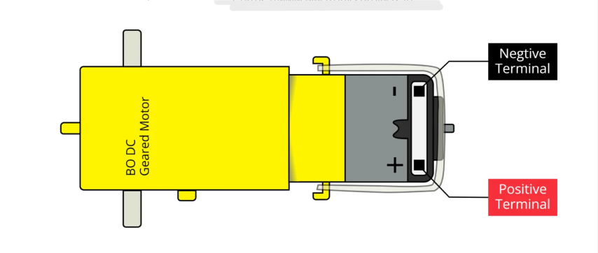
Geared DC Motor Pinout Diagram:
The BO motor is having two terminals, one of which is Positive and the another is negative terminal
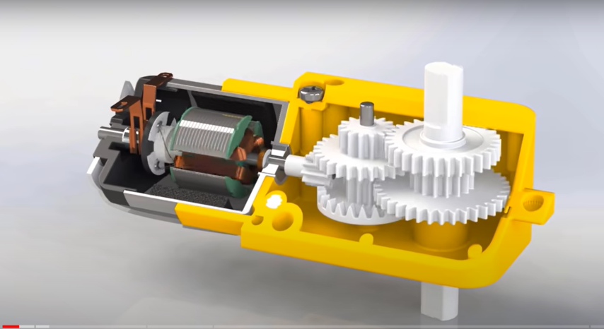
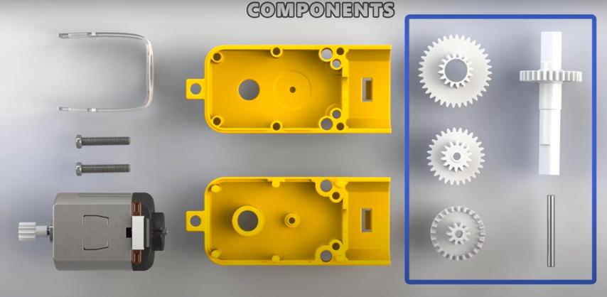
Motor components:
The motor consists of a DC (Direct Current) motor and a gearbox, which provides the motor with the ability to produce higher torque output than a regular DC motor. The gearbox is designed to reduce the speed of the motor while increasing its torque output.
Motor Driver:-
A motor driver is an electronic device or circuit that controls the speed and direction of a motor by regulating the electrical power supplied to it.
Motor drivers are commonly used in robotics, automation, electric vehicles, and other electromechanical systems to drive various types of motors, including DC motors, stepper motors, and brushless DC motors.
They provide the necessary voltage, current, and control signals to the motor, enabling precise speed and torque control for different applications.
Motor drivers come in various configurations, such as H-bridge, brushed DC motor drivers, stepper motor drivers, and integrated motor driver ICs.
They are designed to handle the high currents and voltages required to drive motors efficiently and safely, protecting both the motor and the driving circuitry from damage.
Motor drivers can be controlled using microcontrollers, PWM (Pulse Width Modulation) signals, or other control interfaces to adjust motor speed, direction, and acceleration dynamically.
They often feature built-in protection mechanisms such as overcurrent protection, thermal shutdown, and reverse polarity protection to ensure reliable operation and prevent damage under adverse conditions.

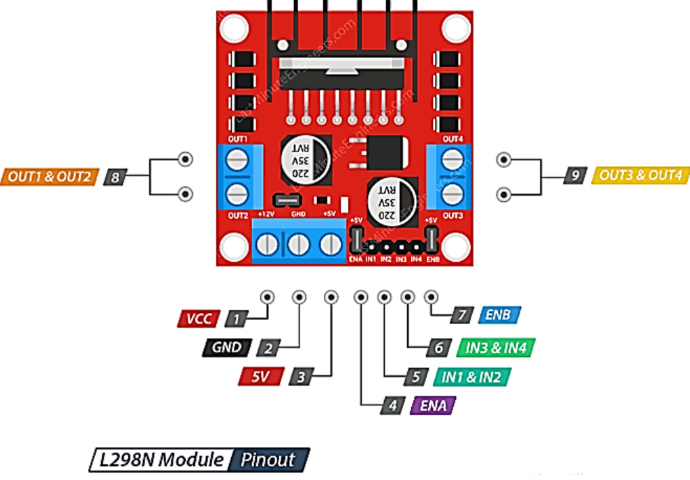
Motor Driver Pinout Diagram:
The pinout diagram for a motor driver typically includes connections for power input, motor outputs, control inputs, and auxiliary functions.
Commonly found pins in a motor driver pinout diagram may include:
- VCC: This pin is used to supply power to the motor driver circuit. It typically requires a voltage within a specified range, such as 5V or 12V.
- GND: This pin is the ground connection for the motor driver, providing the reference voltage for the circuit.
- Motor Outputs: These pins are connected to the terminals of the motor and provide the driving current to the motor coils or windings.
- Control Inputs: These pins accept control signals from a microcontroller or other control circuitry to adjust motor speed, direction, and other parameters.
- Enable: This pin enables or disables the motor driver, allowing the motor to be turned on or off remotely.
- Brake: This pin applies a braking action to the motor, bringing it to a quick stop by shorting the motor terminals.
The pinout diagram provides a visual representation of these connections, aiding in the proper wiring and integration of the motor driver into electronic projects or systems.
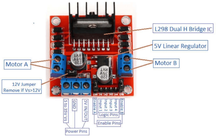
Motor Driver Components:
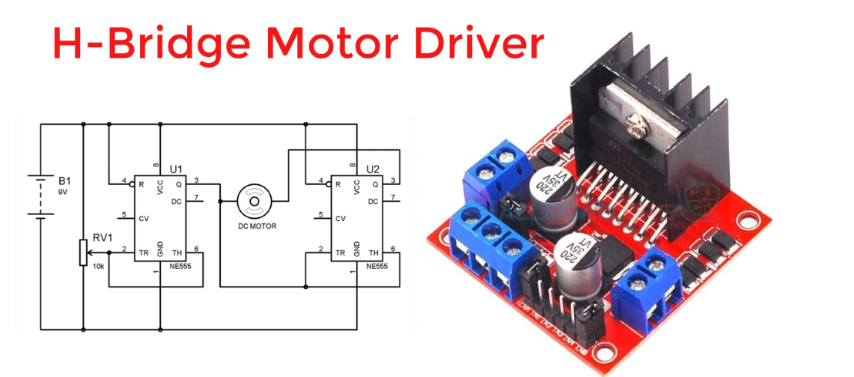
The main components of a motor driver include power MOSFETs (Metal-Oxide-Semiconductor Field-Effect Transistors), H-bridge circuitry, gate drivers, current sensing circuitry, and protection circuits.
Power MOSFETs act as switches to control the flow of current to the motor, providing efficient power delivery and minimizing losses.
H-bridge circuitry enables bidirectional control of the motor, allowing it to rotate in both forward and reverse directions.
Gate drivers provide the necessary voltage and current to drive the MOSFETs, ensuring fast switching speeds and minimal heat dissipation.
Current sensing circuitry monitors the motor current to prevent overloading and protect the motor and driver from damage.
Protection circuits such as overcurrent protection, thermal shutdown, and reverse polarity protection safeguard the motor driver and connected components under fault conditions.
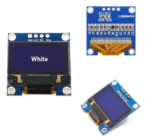
OLED Display:-
OLED (Organic Light Emitting Diode) displays use organic compounds that emit light when an electric current is applied. They offer high contrast ratios, wide viewing angles, and fast response times.
OLED displays come in various sizes and configurations, catering to different applications such as smartphones, TVs, wearable devices, and automotive displays.
They are known for their thinness, flexibility, and energy efficiency compared to traditional LCD (Liquid Crystal Display) technology.
OLED displays are capable of producing vibrant colors and deep blacks, providing an immersive viewing experience for users.
Due to their versatility and superior performance, OLED displays are widely used in consumer electronics, signage, medical devices, and industrial applications.
They can be interfaced with microcontrollers or display drivers to showcase text, graphics, and animations, making them ideal for a wide range of projects and products.
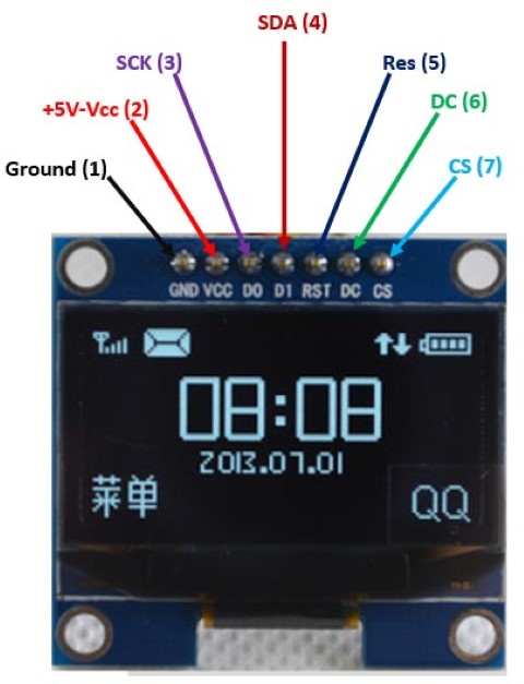
OLED Display Pinout Diagram:
The pinout diagram for an OLED display typically includes connections for power, data, and control signals.
Commonly found pins in an OLED display pinout diagram may include:
- VCC: This pin is used to supply power to the OLED display. It typically requires a voltage within a specified range, such as 3.3V or 5V.
- GND: This pin is the ground connection for the OLED display, providing the reference voltage for the circuit.
- SCL (Serial Clock): SCL is used for the clock signal in serial communication protocols like I2C or SPI. It synchronizes the data transfer between the microcontroller and the display.
- SDA (Serial Data): SDA is the data line used for bidirectional communication between the microcontroller and the OLED display in protocols like I2C or SPI.
- RST (Reset): This pin is used to reset the OLED display, restoring it to a known state. It may be connected to a microcontroller pin to initiate a reset sequence.
- D/C (Data/Command): This pin determines whether data or commands are being sent to the OLED display. It distinguishes between control signals and pixel data.
The pinout diagram provides a visual representation of these connections, aiding in the integration of the OLED display into electronic projects or systems.
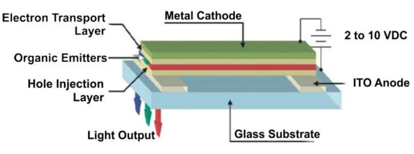
OLED Display Components:
The main components of an OLED display include organic light-emitting diodes (OLEDs), thin-film transistor (TFT) arrays, glass substrates, and encapsulation layers.
Each pixel in an OLED display consists of organic layers sandwiched between two electrodes, which emit light when an electric current passes through them.
TFT arrays control the flow of current to each pixel, enabling precise control over brightness and color.
Glass substrates provide structural support for the OLED layers and TFT arrays, while encapsulation layers protect the organic materials from moisture and oxygen, prolonging the lifespan of the display.
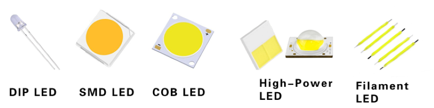
LED (Light Emitting Diode):-
LEDs (Light Emitting Diodes) are semiconductor devices that emit light when an electric current passes through them. They are widely used for various lighting applications due to their efficiency, durability, and versatility.
LEDs come in different shapes, sizes, and colors, catering to diverse lighting needs ranging from indicator lights and backlighting to general illumination and decorative lighting.
They offer several advantages over traditional incandescent and fluorescent lights, including lower energy consumption, longer lifespan, instant illumination, and better environmental sustainability.
LED technology has evolved rapidly, leading to the development of high-brightness LEDs capable of producing intense light output for applications such as automotive headlights, stadium lighting, and street lighting.
LEDs can be controlled dynamically to adjust brightness levels and color temperatures, making them suitable for dynamic lighting scenarios and mood lighting installations.
They are commonly integrated into electronic circuits using resistors to limit current flow and protect them from damage due to overcurrent.
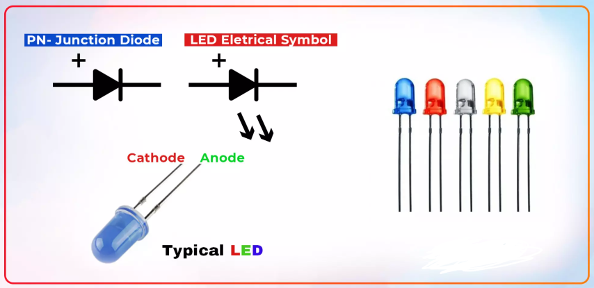
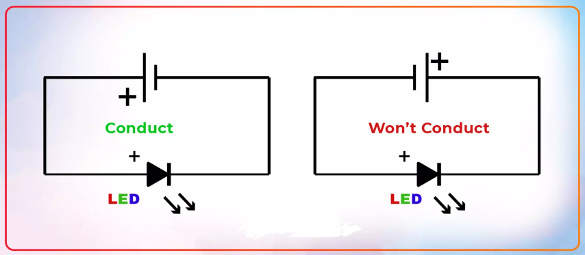
LED Pinout Diagram:
The pinout diagram for an LED typically includes connections for the anode (positive terminal) and cathode (negative terminal).
Commonly found pins in an LED pinout diagram may include:
- Anode (+): This pin is the positive terminal of the LED, connected to the longer lead or the lead with a flat edge on the LED package.
- Cathode (-): This pin is the negative terminal of the LED, connected to the shorter lead or the lead with a rounded edge on the LED package.
The pinout diagram provides a visual representation of these connections, aiding in the proper orientation and connection of the LED in electronic circuits.
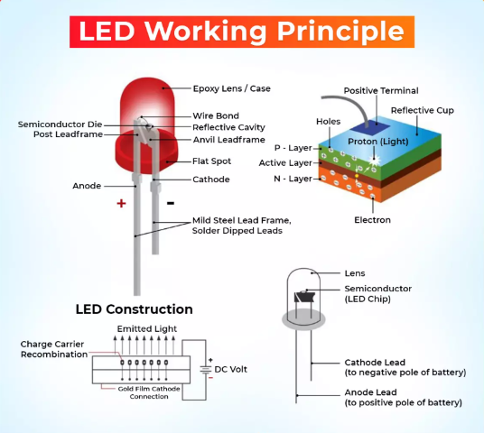
LED Components:
The main components of an LED include a semiconductor chip, encapsulating material, lead frames, and a package.
The semiconductor chip is the heart of the LED, where light emission occurs when electrons and electron holes recombine across the junction of different semiconductor materials.
The encapsulating material surrounds the semiconductor chip, providing mechanical support, thermal management, and protection from environmental factors.
Lead frames are metal wires or strips used to connect the semiconductor chip to the external electrical contacts, enabling the flow of current through the LED.
The package houses all the components of the LED and provides electrical insulation, mechanical stability, and optical control to direct the emitted light.
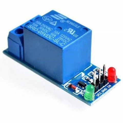
Single Channel Relay Module:-
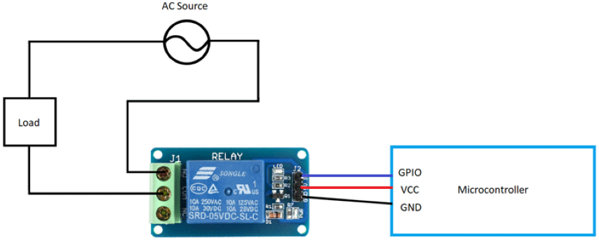
A single-channel relay module is an electronic device designed to control the switching of a single electrical circuit by using a low-power signal. It is commonly used in various electronic projects and automation systems for switching high-power devices such as lights, appliances, motors, and heaters.
The relay module consists of a relay switch, control circuitry, and terminal blocks for easy connection to external devices. It provides isolation between the low-voltage control signal and the high-voltage load circuit, ensuring safety and preventing damage to the controlling device.
Single-channel relay modules are typically used in applications where only one electrical circuit needs to be controlled, such as turning a light on or off, activating a motor, or switching a heating element.
They are compatible with a wide range of microcontrollers, Arduino boards, Raspberry Pi, and other control systems, allowing for easy integration into various projects and prototypes.
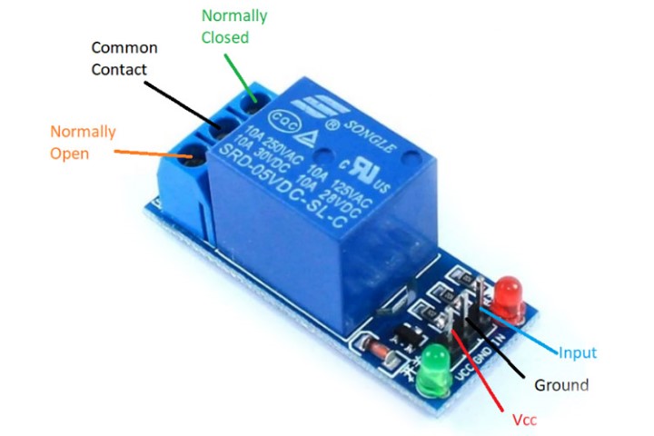
Single-channel relay modules are available in different configurations, including normally open (NO), normally closed (NC), and common terminal (COM), providing flexibility for different switching requirements.
They can be controlled using digital or analog signals, allowing for simple on/off control or more complex switching operations based on sensor inputs or programmed logic.
Single Channel Relay Module Pinout Diagram:
The pinout diagram for a single-channel relay module typically includes connections for power input, control input, and load output.
Commonly found pins in a single-channel relay module pinout diagram may include:
- VCC: This pin is used to supply power to the relay module. It typically requires a low-voltage DC power source, such as 5V or 12V.
- GND: This pin is the ground connection for the relay module, providing the reference voltage for the circuit.
- IN (Control Input): This pin accepts a control signal to activate or deactivate the relay switch. It is often connected to a microcontroller or digital output pin.
- NO (Normally Open): This terminal is connected to the load circuit and remains open when the relay is not energized. It closes when the relay is activated, allowing current to flow through the load.
- COM (Common): This terminal is common to both the NO and NC terminals and is usually connected to one side of the load circuit.
- NC (Normally Closed): This terminal is connected to the load circuit and remains closed when the relay is not energized. It opens when the relay is activated, interrupting the current flow through the load.
The pinout diagram provides a visual representation of these connections, aiding in the proper wiring and integration of the single-channel relay module into electronic projects or systems.
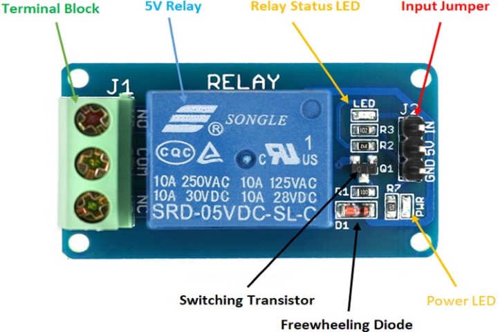
Single Channel Relay Module Components:
The main components of a single-channel relay module include a relay switch, transistor driver, flyback diode, LED indicator, and terminal blocks.
The relay switch is the heart of the module, responsible for controlling the electrical circuit. It consists of an electromagnetic coil and one or more sets of contacts.
The transistor driver amplifies the control signal from the microcontroller to energize the relay coil, allowing for reliable switching of high-power loads.
The flyback diode protects the transistor and control circuitry from voltage spikes generated by the relay coil when it is de-energized, preventing damage to sensitive components.
The LED indicator provides visual feedback of the relay status, indicating whether the relay is activated or deactivated.
Terminal blocks are used for easy and secure connection of external wires to the relay module, facilitating installation and maintenance.
This week there are two types of assignments, one group and one individual.
Group Assignment :-
- Measure the power consumption of an output device
- Document your work.
- Add an output device to a microcontroller board you've designed and program it to do something.
- Linked to the group assignment page.
- Documented how you determined power consumption of an output device with your group.
Visit our Group assignment page here
Group Assignment Brief:
Individual Assignment:-
- Documented what you have learned in Output Devices
- Add an output device to a microcontroller board you have designed.
- Included original design files of Program.
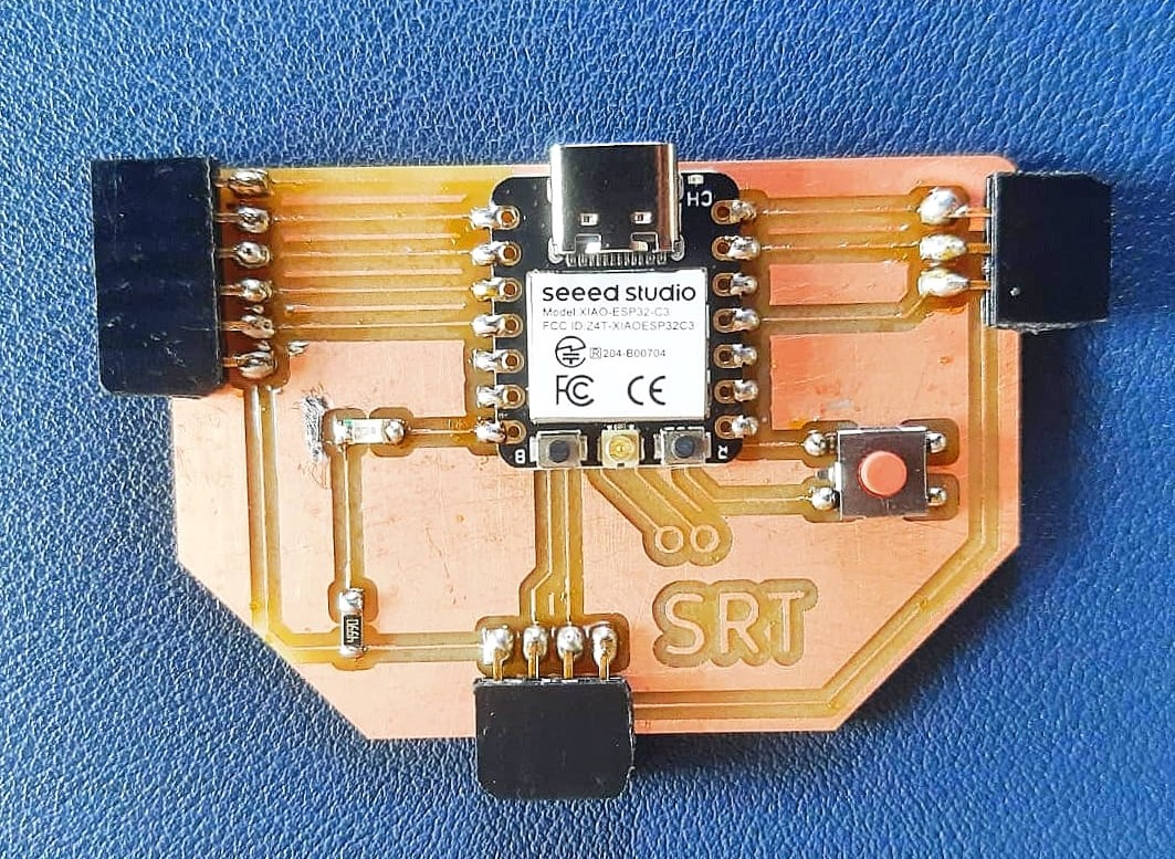
- Included a ‘hero shot’ of your board.
- Loaded a program and tested if your board works
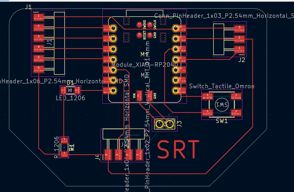
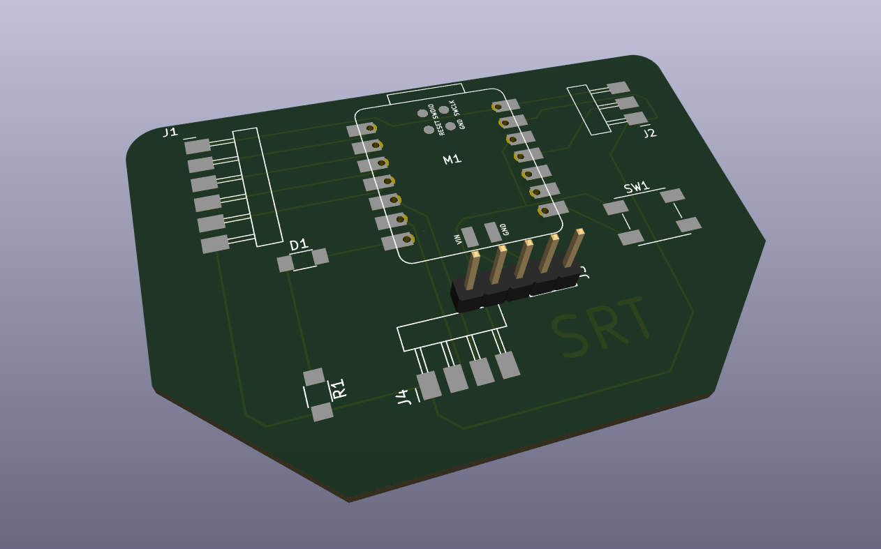
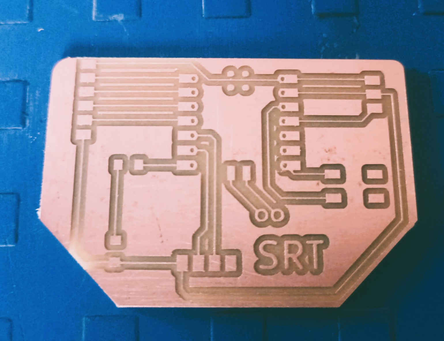
Output Board Making Process
You can refer my previous Assignment Page for the detailed Process of making a board.
Adding Output Devices
So I am going to try a LED, a BO motor, an OLED Display and a Relay on my Board as an Output devices
Firstly I have selected to startup with my LED on my Board, so I have Programed the board to test the LED
I have also tried with a external LED to connect on a digital pin at the external 3 pin connector provided on the board.
Problems Faced and Solutions
While designing the PCB board in Kicad software, the trace width which I select was not actually, applying to the traces and when I convert the Svg file the traces seems to be very thin. To solve this I go to the track use net class width in the PCB Routing environment to edit the predefined sizes.
