Week 08
Electronics Design
Brief Overview
In this week of FabAcademy, my individual assignment involved creating and implementing a program for a microcontroller development board that I made in Electronics production week. This program facilitates interaction with local input/output devices and communication with remote devices, utilizing both wired and wireless connections. As an extra credit endeavor, I incorporated different programming languages and development environments, and further expanded the project by connecting external components to the board. Concurrently, our group assignment revolved around an extensive exploration of the microcontroller's datasheet, allowing us to compare its performance and development workflows with other architectures. This comprehensive approach not only deepened my understanding of embedded programming but also provided valuable insights into the diverse landscape of microcontroller architectures and their applications, aligning seamlessly with the goals of FabAcademy.
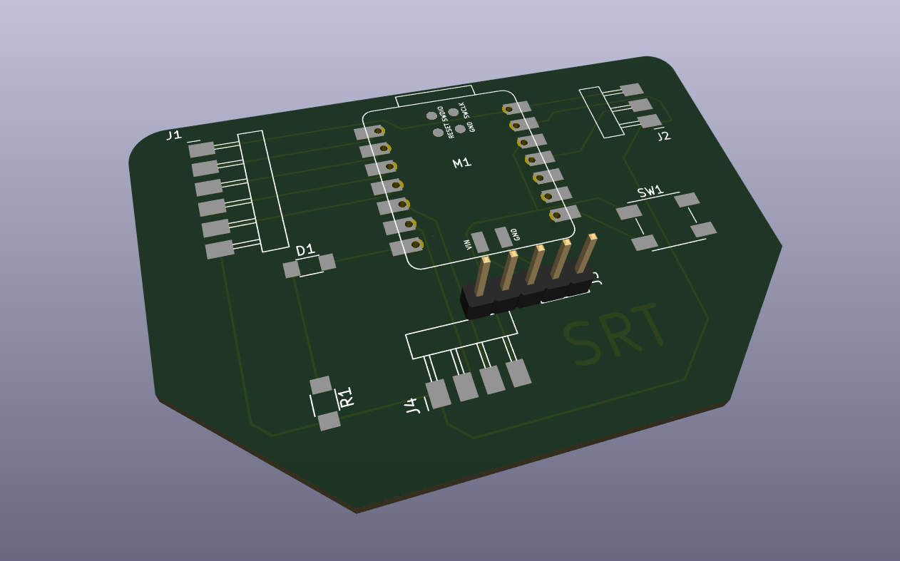
My Heroshot for this Week
 |
 |
 |
 |
Basics of Electronics
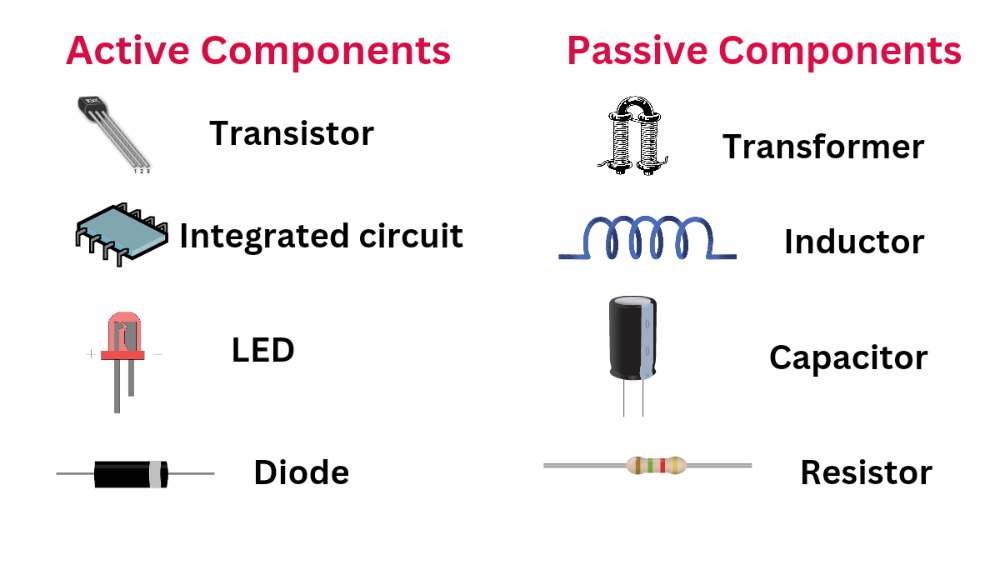
Electronics, as a division of physics and electrical engineering, is concerned with the emission, behavior, and impacts of electrons through the utilization of electronic apparatus. Active devices within electronics regulate the flow of electrons via amplification and rectification, setting it apart from classical electrical engineering, where passive elements like resistance, capacitance, and inductance govern electric current flow exclusively.
The advent of electronics has wielded a profound impact on the evolution of contemporary civilization. The discovery of the electron in 1897, coupled with the subsequent creation of the vacuum tube capable of amplifying and rectifying minute electrical signals, marked the inception of the electronics era. Practical advancements commenced with Ambrose Fleming's development of the diode and Lee De Forest's creation of the triode in the early 1900s, enabling the detection of faint electrical voltages, such as radio signals, sans mechanical means. The expansion of electronics was swift, with commercial radio broadcasting and communication networks proliferating by the early 1920s, and electronic amplifiers finding diverse applications, including long-distance telephony and the burgeoning music recording industry.
Prior to delving deeper into electronic devices, components, testing apparatus, and similar topics, it is imperative to acquaint ourselves with fundamental terminologies, concepts, and principles in electronics, such as those listed below.
Current
Two primary types of electrical signals exist: alternating current (AC) and direct current (DC).
Voltage
Resistance
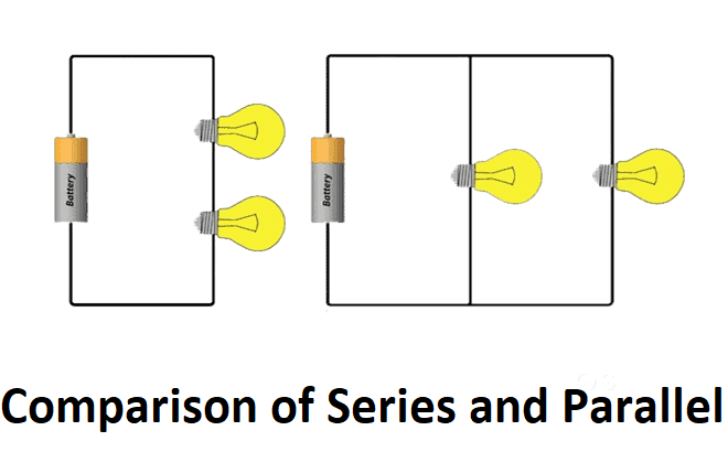
DC Series and Parallel Circuits
Kirchhoffs Circuit Laws
|
|
Electronic Devices and Components
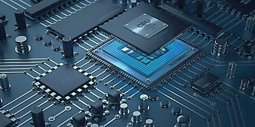
Microprocessor v/s Microcontroller
Functionality:
- Microcontroller: A compact integrated circuit that includes a processor core, memory (RAM and/or ROM), input/output peripherals, timers, and sometimes additional features like analog-to-digital converters. Designed for specific applications in embedded systems.
- Microprocessor: A central processing unit (CPU) that performs general-purpose processing tasks. Lacks built-in peripherals and is typically used in conjunction with external components like memory, input/output devices, and support chips. Found in devices requiring general-purpose computing capabilities.
Applications:
- Microcontroller: Commonly used in embedded systems for specific applications, such as in consumer electronics (e.g., washing machines, microwave ovens), automotive control systems, industrial automation, and various electronic gadgets.
- Microprocessor: Found in general-purpose computing devices, such as personal computers, servers, laptops, and workstations, where versatility and the ability to run a wide range of applications are crucial.
| Feature | Microprocessor | Microcontroller |
|---|---|---|
| Components | CPU only | CPU, memory (RAM, ROM), and I/O peripherals |
| Integration | Requires external components (memory, I/O) | All components integrated on a single chip |
| Complexity | More complex due to external connections | Simpler due to integrated components |
| Cost | Generally more expensive | Generally less expensive |
| Power consumption | Higher power consumption | Lower power consumption |
| Applications | Personal computers, laptops, smartphones | Embedded systems (washing machines, toys, drones) |
In summary, microprocessors are powerful and flexible general-purpose processors, while microcontrollers are self-contained, low-power devices designed for specific tasks in embedded systems.
Microcontroller
This week there are two types of assignments, one group and one individual.
Group Assignment :-
- Use the test equipment in your lab to observe the operation of a microcontroller circuit board (in minimum, check operating voltage on the board with multimeter or voltmeter and use oscilloscope to check noise of operating voltage and interpret a data signal).
- Redraw one of the echo hello-world boards or something equivalent, add (at least) a button and LED (with current-limiting resistor) or equivalent input and output, check the design rules, make it, test it.
- Linked to the group assignment page.
Visit our Group assignment page here
Group Assignment Brief:
Step 9: Live Testing
Individual Assignment:-
- Documented what you have learned in electronics design.
- Explained problems and how you fixed them.
- Included original design files of PCBs.
- Included a ‘hero shot’ of your board.
- Loaded a program and tested if your board works
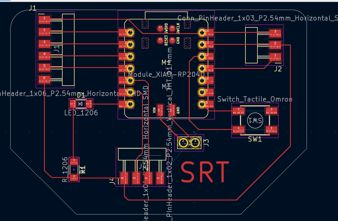
PCB Designing
PCB design is a fascinating process that bridges the gap between circuit schematics and functional electronic devices. Here's a look beyond the basic steps to give you a broader understanding:

Design Considerations:
- Signal integrity: PCB layout significantly impacts signal quality. Consider factors like trace length, impedance, and crosstalk to ensure proper signal transmission and minimize noise.
- Power integrity: Plan for adequate power distribution and grounding to avoid voltage drops and maintain stable power supply throughout the PCB.
- Thermal management: Certain components generate heat. Consider heat sinks, copper plane size, and component placement to dissipate heat effectively and prevent overheating.
- EMC (Electromagnetic Compatibility): Minimize unwanted electromagnetic interference (EMI) and susceptibility (EMS) by using proper grounding techniques, shielding, and component selection.
- Manufacturability: Design your PCB with manufacturability in mind. Consider factors like minimum trace width, drill hole size limitations, and standard component footprints to avoid issues during fabrication.
Advanced PCB Design Techniques:
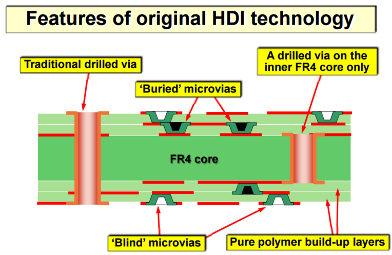
High-Density Interconnect (HDI): This technique allows for packing more components into a smaller space by using finer trace widths, microvias, and stacked layers.
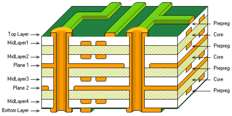
Multi-layer PCBs: These PCBs have more than two copper layers, enabling complex routing and improved signal integrity for high-frequency circuits.
Rigid-Flex PCBs: These combine rigid and flexible sections, offering unique design possibilities for applications requiring flexibility or space constraints.

Software Features:
- Design Rule Checks (DRC): Advanced DRC tools can identify potential electrical shorts, opens, and other layout violations during the design process.
- Signal integrity analysis: Simulation tools within KiCad or other software can help analyze signal behavior on the PCB, allowing for adjustments before fabrication.
- 3D modeling and visualization: Advanced PCB design tools offer 3D modeling capabilities for visualizing component clearances and potential assembly issues.
Learning Resources:
- KiCad offers extensive documentation and tutorials: KiCad Downloads
- Online communities and forums provide valuable insights and troubleshooting assistance.
- Books and online courses dedicated to PCB design offer in-depth knowledge and best practices.
Designing a PCB in KiCad: From Schematic to Output Files
KiCad is a powerful open-source software suite for designing Printed Circuit Boards (PCBs). Here's a step-by-step guide to take you from creating a schematic to generating the files needed for PCB manufacturing:
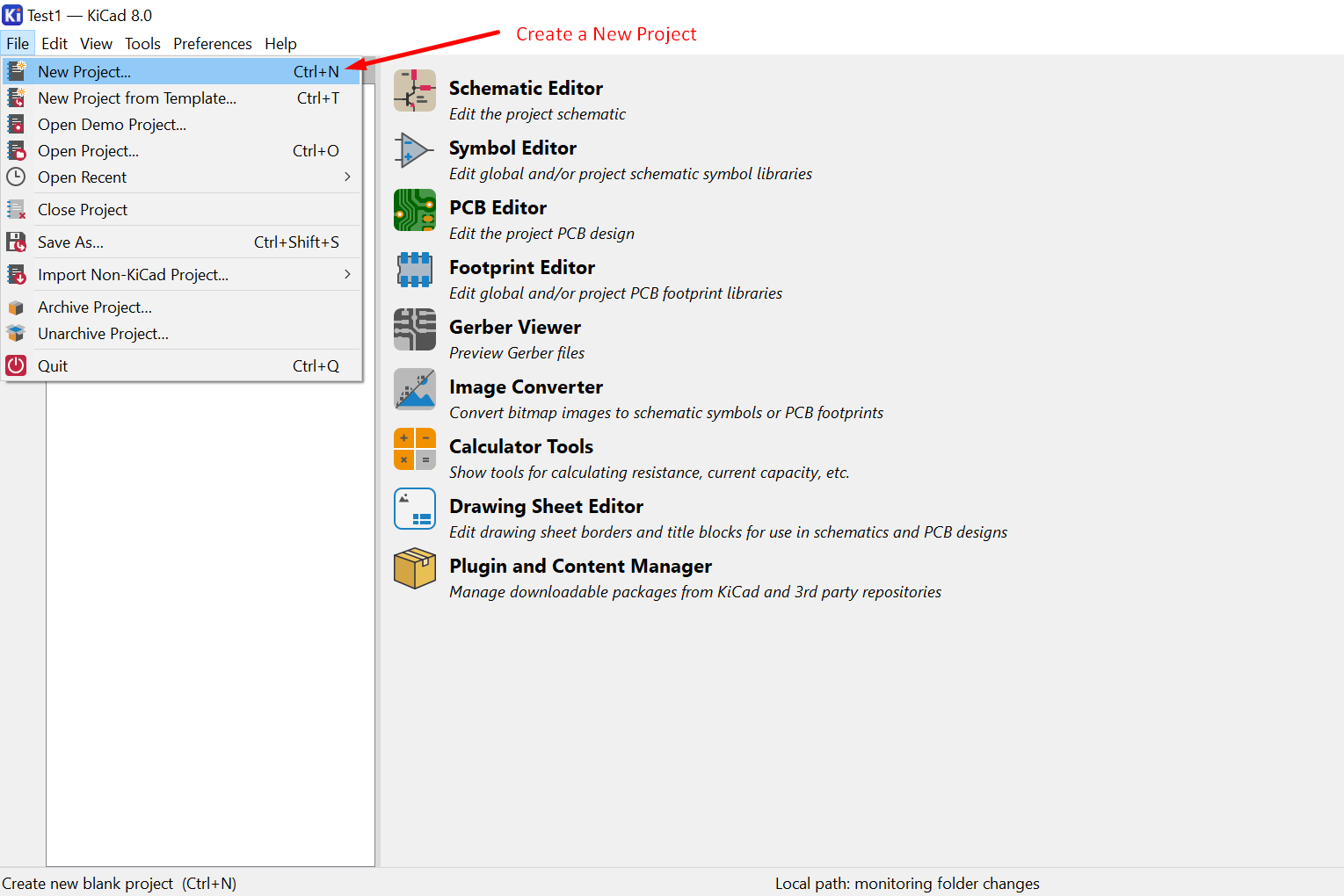
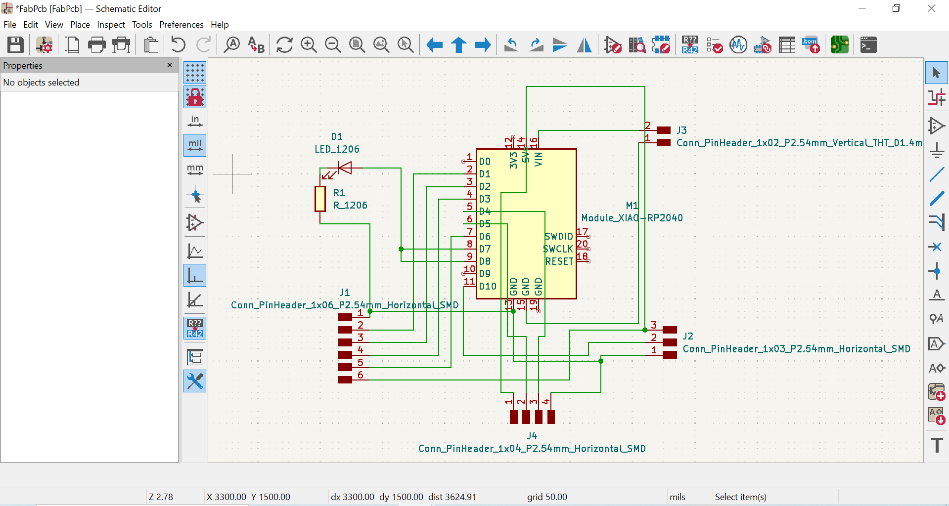
1. Schematic Capture (Eeschema):
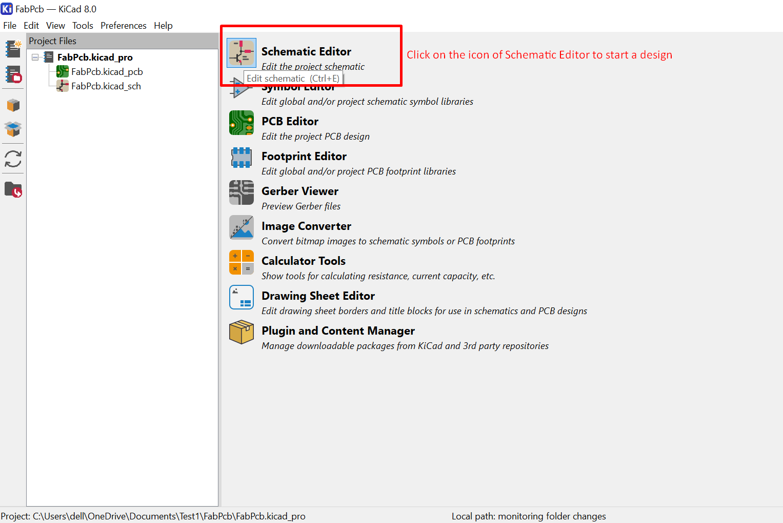
Create a new schematic: Start by creating a new project in KiCad's Eeschema tool.
- Once a new project is open select Schematic Editor
- Add components: Place the electronic components you need from the library onto the schematic.
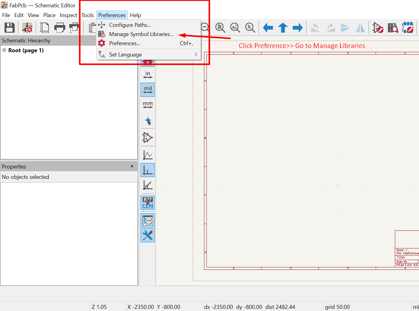
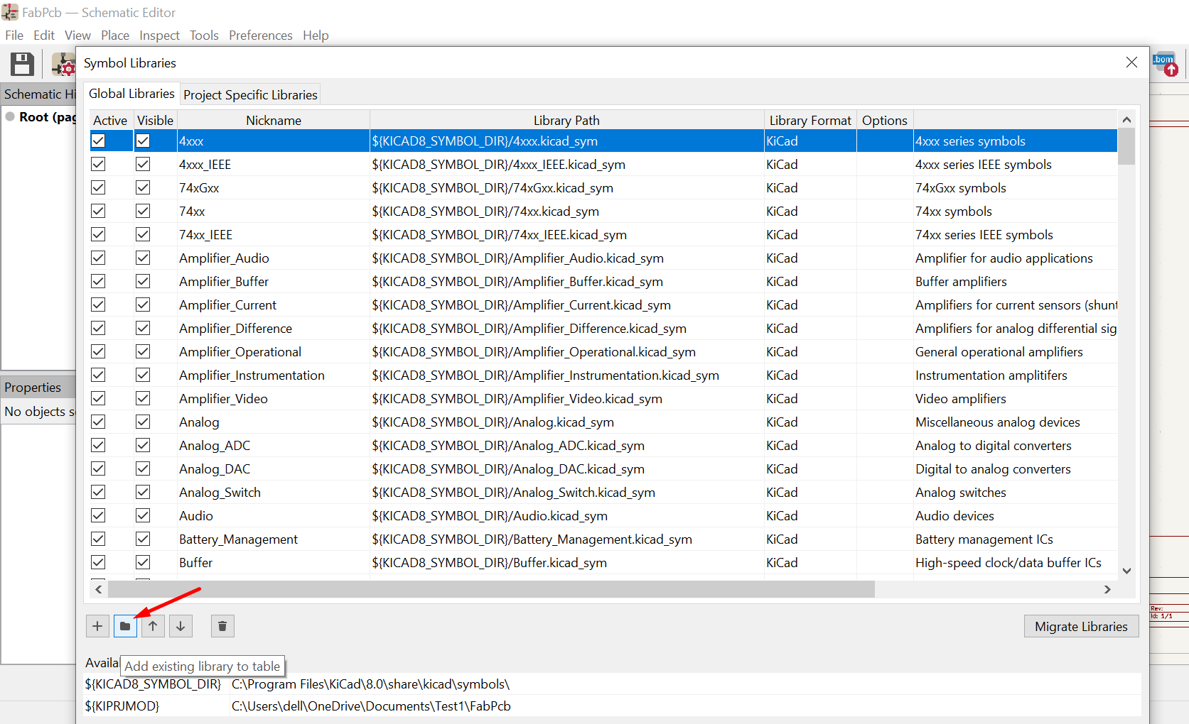
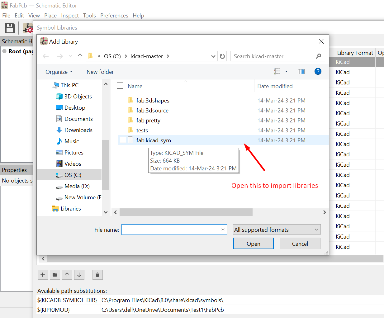
- Add the additional componets from external source other than KiCad libraries
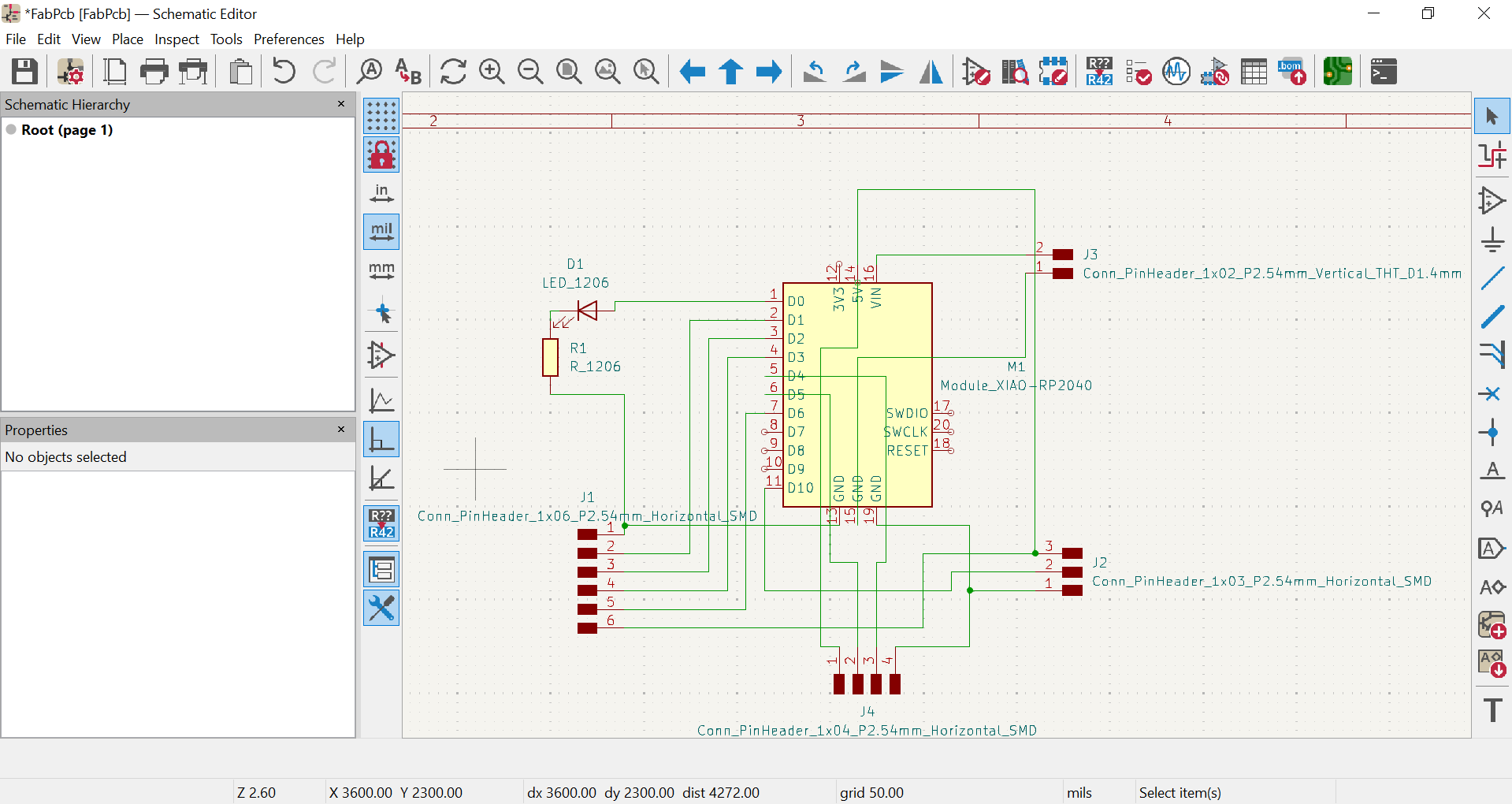
- Connect components: Use wires (nets) to connect the components according to your circuit design.
- Annotate the schematic: Label nets with meaningful names for clarity.
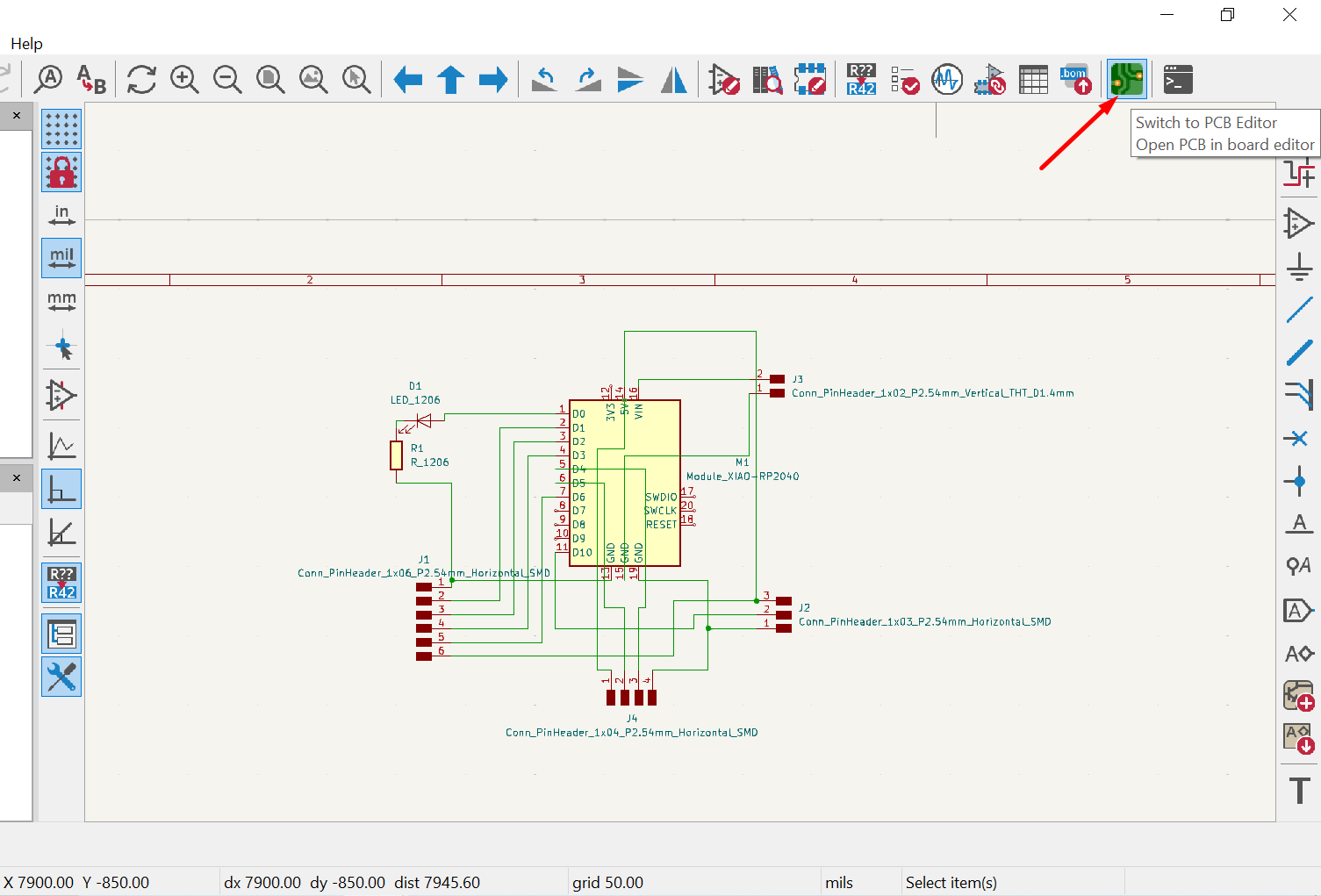
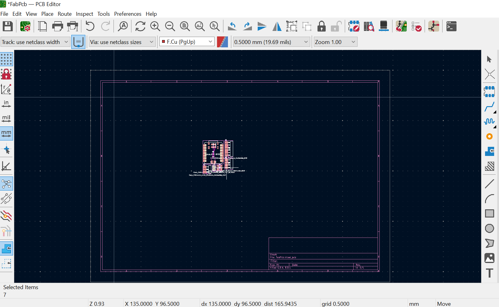
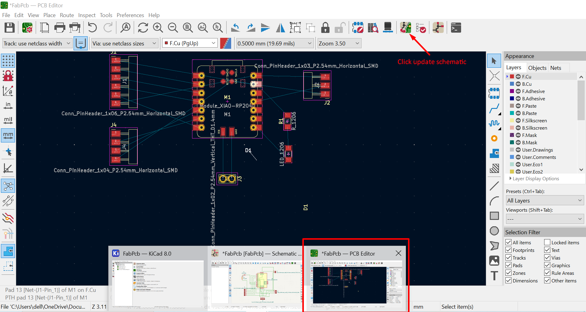
4. PCB Routing (PCBNew):
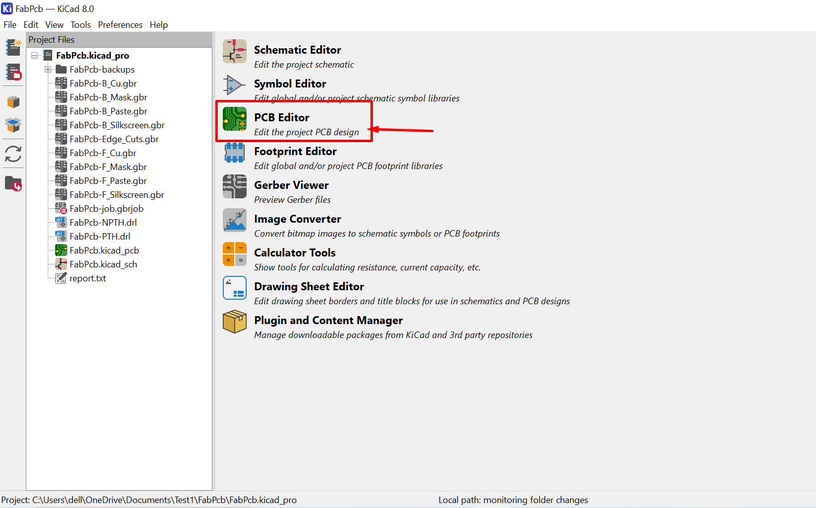
- Now come to the Homepage and Select PCB editor option appeared on 3rd number
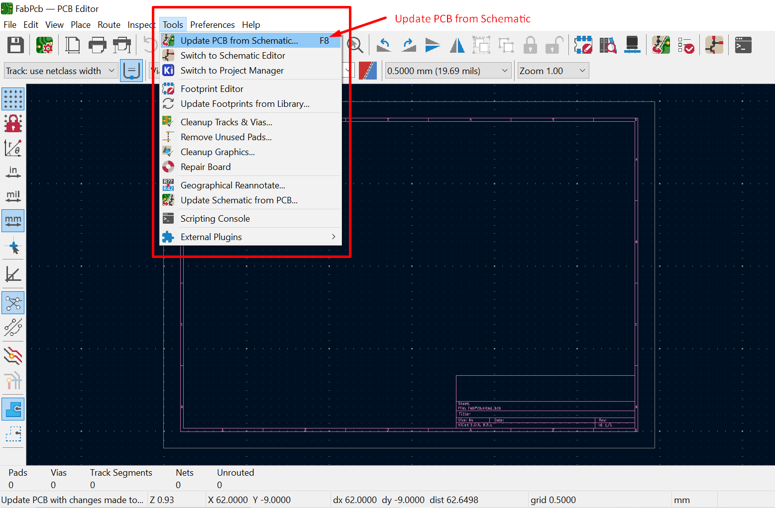
- A new Window opens on the screen, then select Tools from the Nav bar, in the drop down you will find upadte from schematics
- A new window will pop-up with Update PCB from Schematics, click on the Upadte PCB button
- Now all the components will be displayed on your screen.
- Route connections: Use the routing tools to connect components with copper traces following design rules (trace width, clearances).
- Design Rule Checks (DRC): Regularly run DRC to ensure your layout meets manufacturing specifications and avoid electrical shorts.
- I observed that its beong a trouble to connect with vonnection with crossing and keep the track apart, so I again switch to the Schematics window and edited the schematic

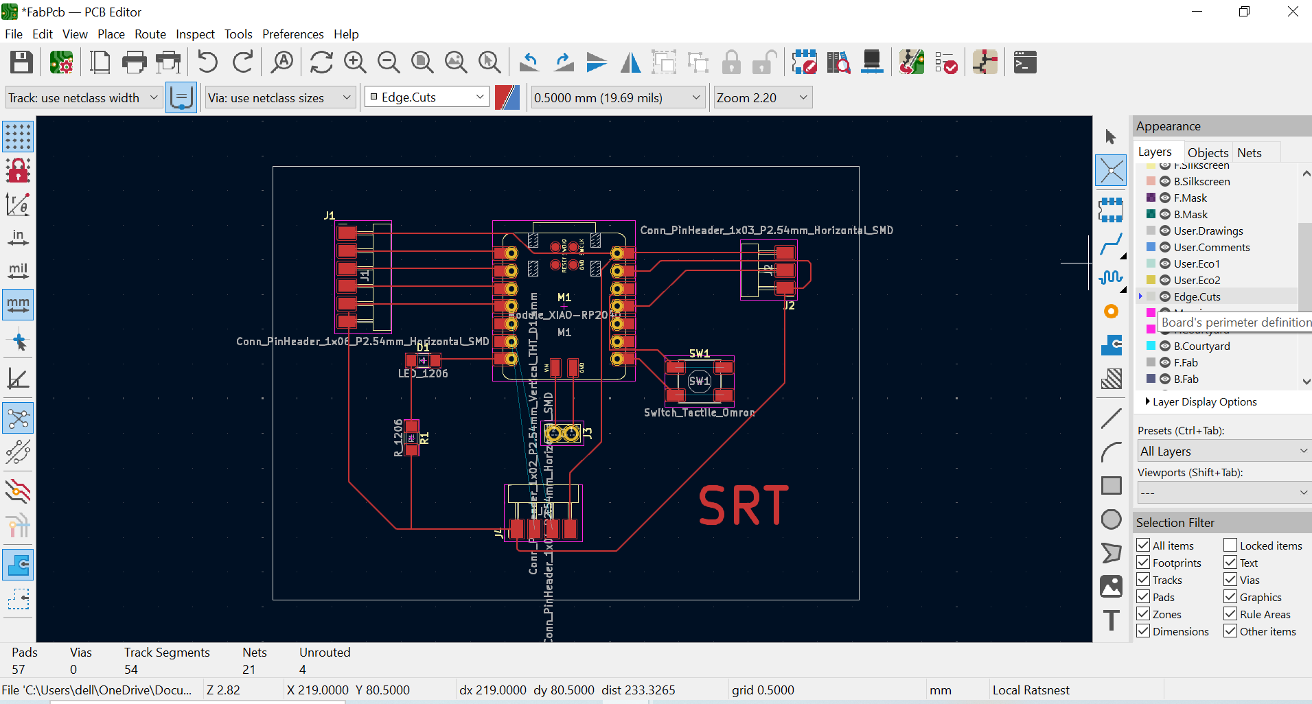
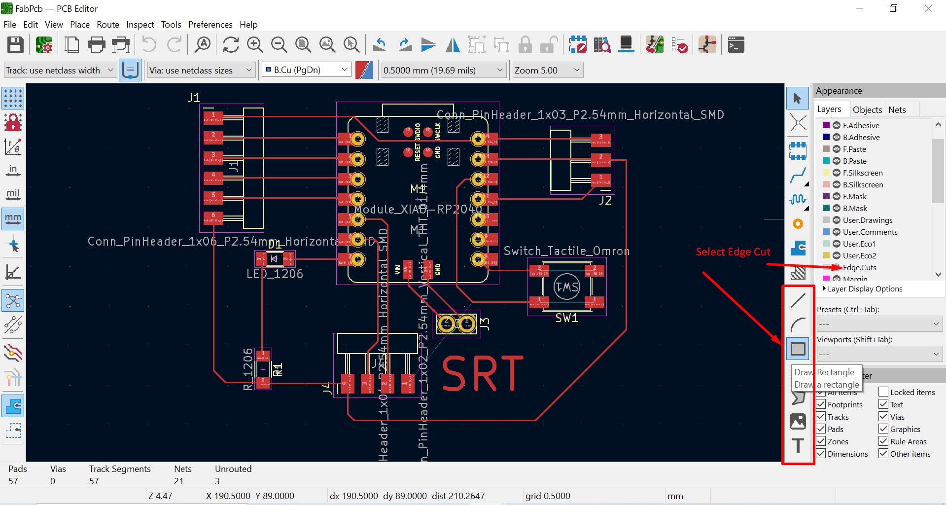
5. Giving the Edge Cuts
- Select any desired shape from the side bar, and make sure that you have selected the edge cut tool
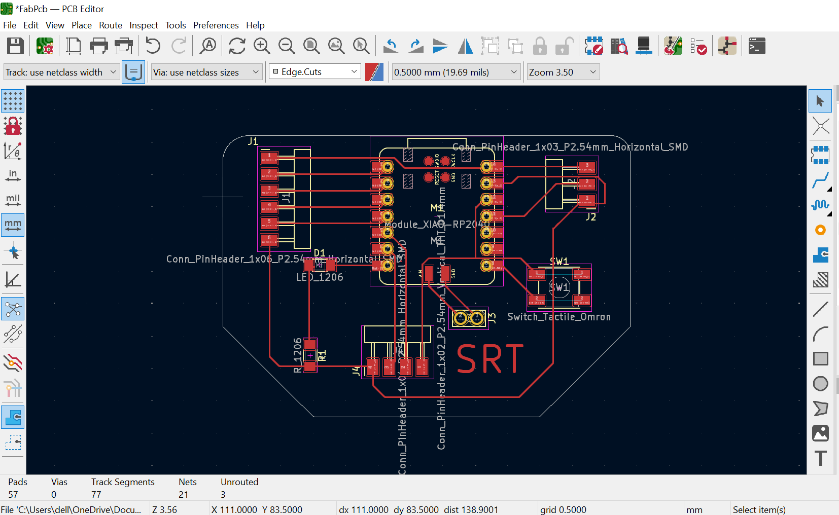
- Now draw a desired cutting shape around your PCB, you made edit it and modify it as per you need.
- Finally your PCB is ready to view in 3D
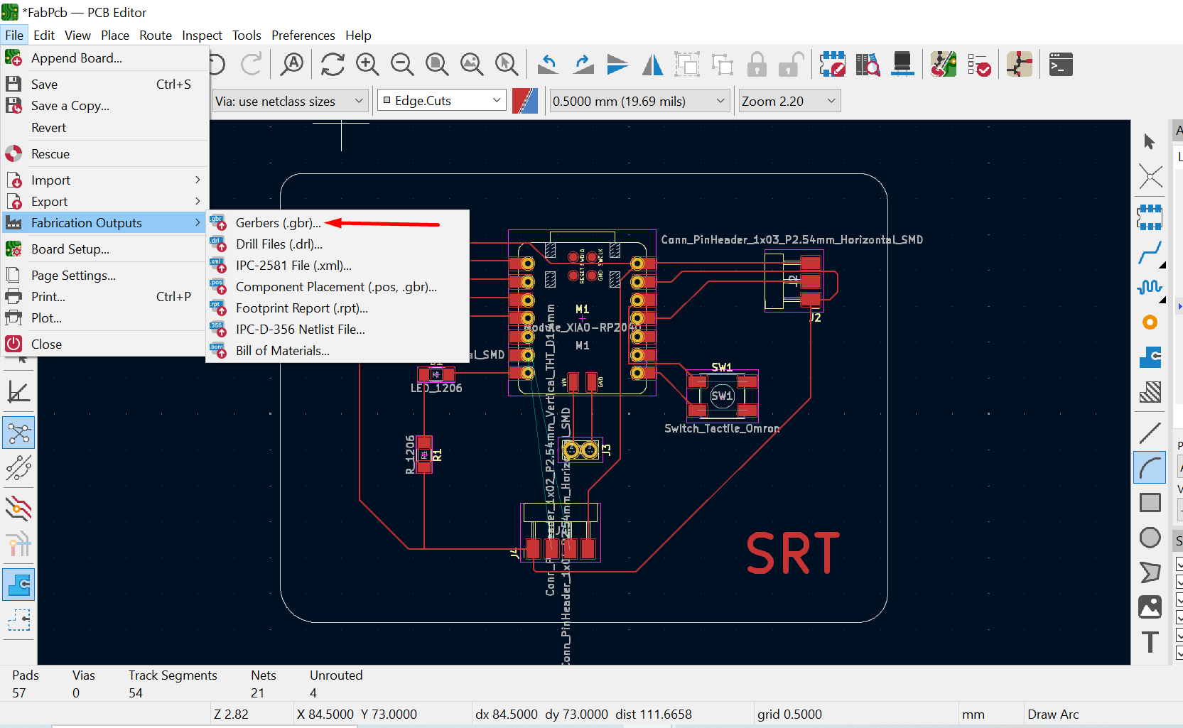
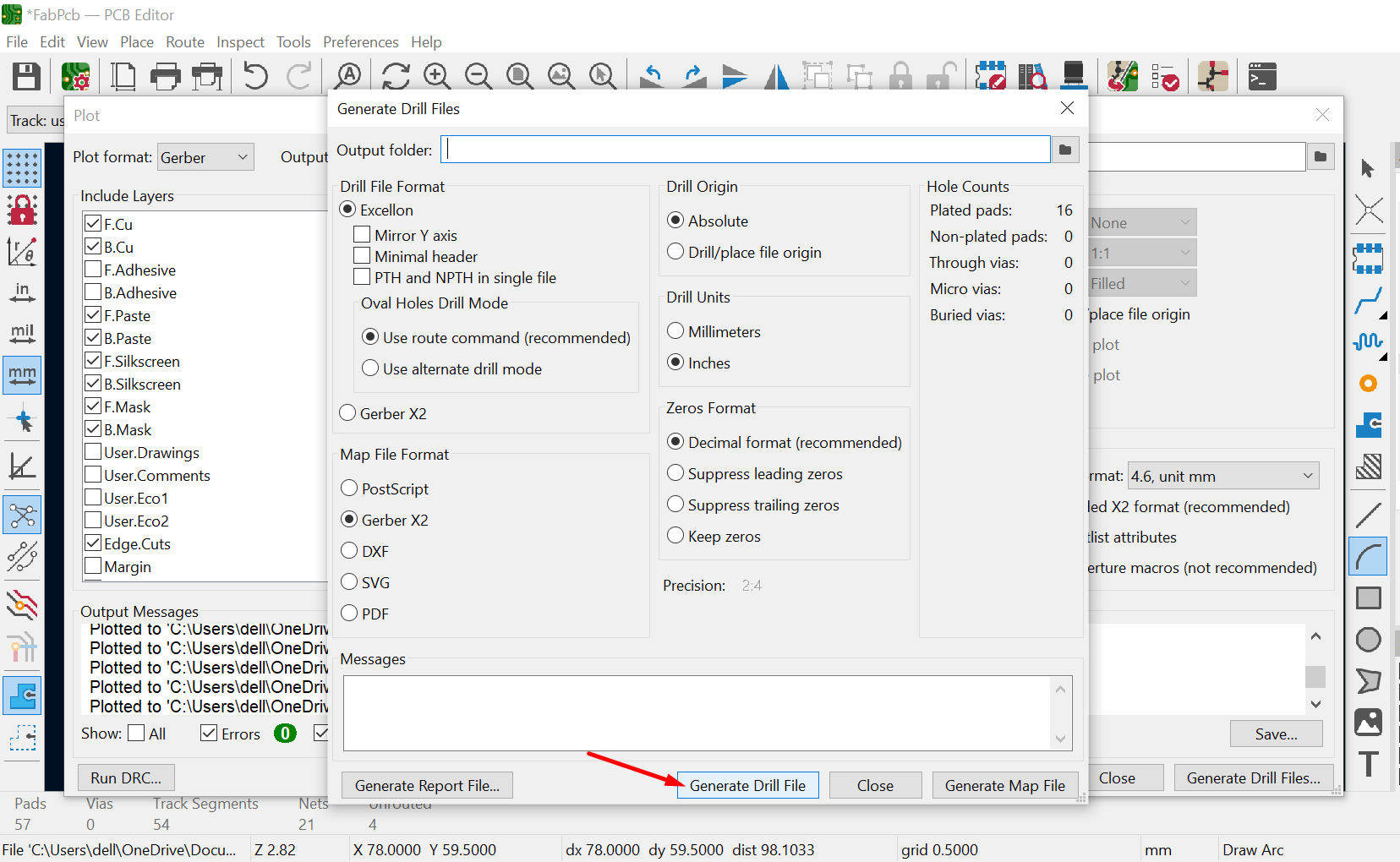
6. Exporting Files (PCBNew):
- Gerber files: Use "File" -> "Fabrication Outputs" to generate Gerber files. These are industry-standard files used by PCB manufacturers to define copper layers, soldermask, silkscreen, etc.
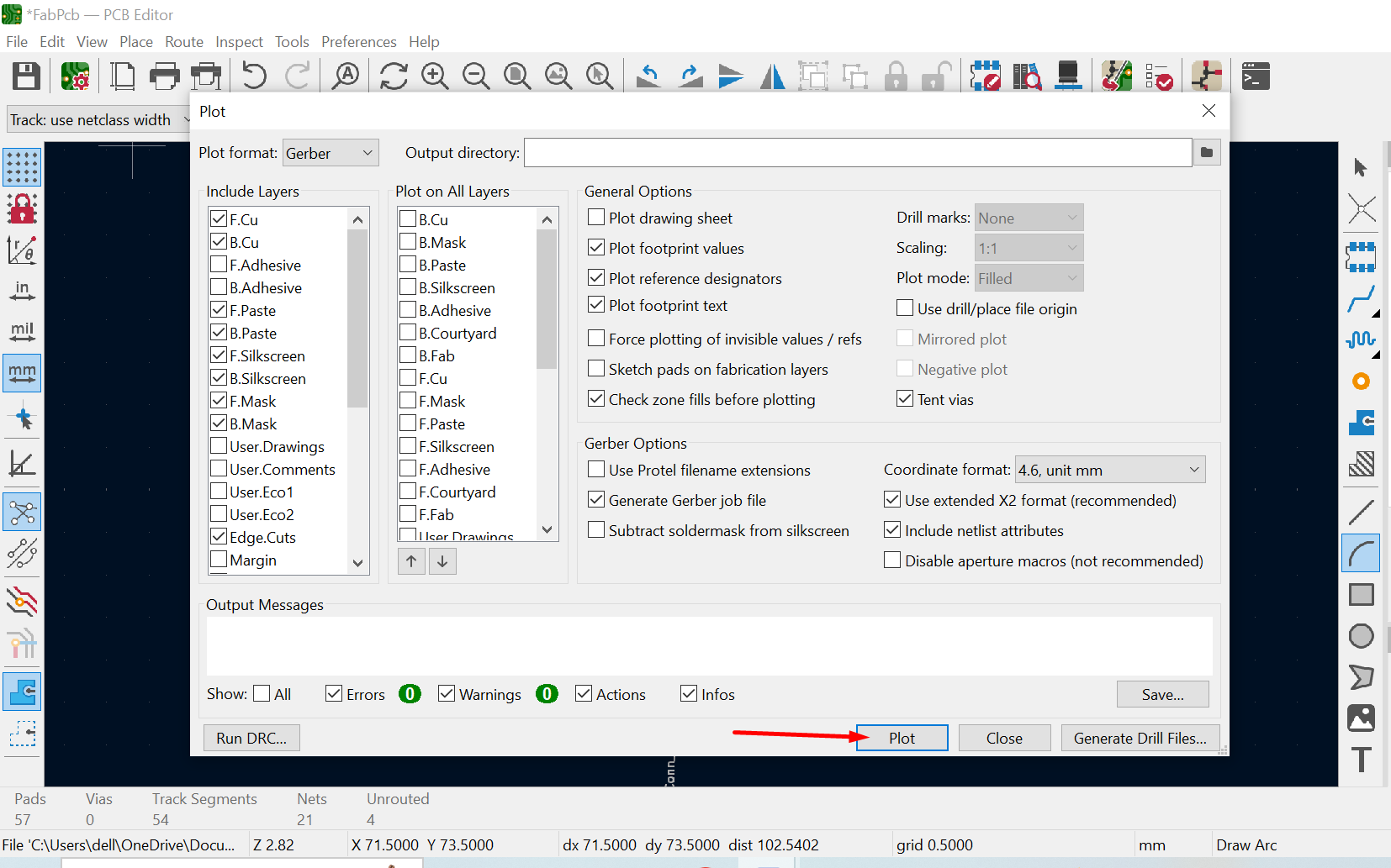
- Select Plots and define the path to save
- Drill file: Generate a drill file defining the drill holes for component leads and mounting.
7. Additional Outputs (Optional):
- Bill of Materials (BOM): Generate a BOM listing all components used in your design.
- Schematic PDF: Use "File" -> "Plot" in Eeschema to create a PDF file of your schematic for documentation purposes.
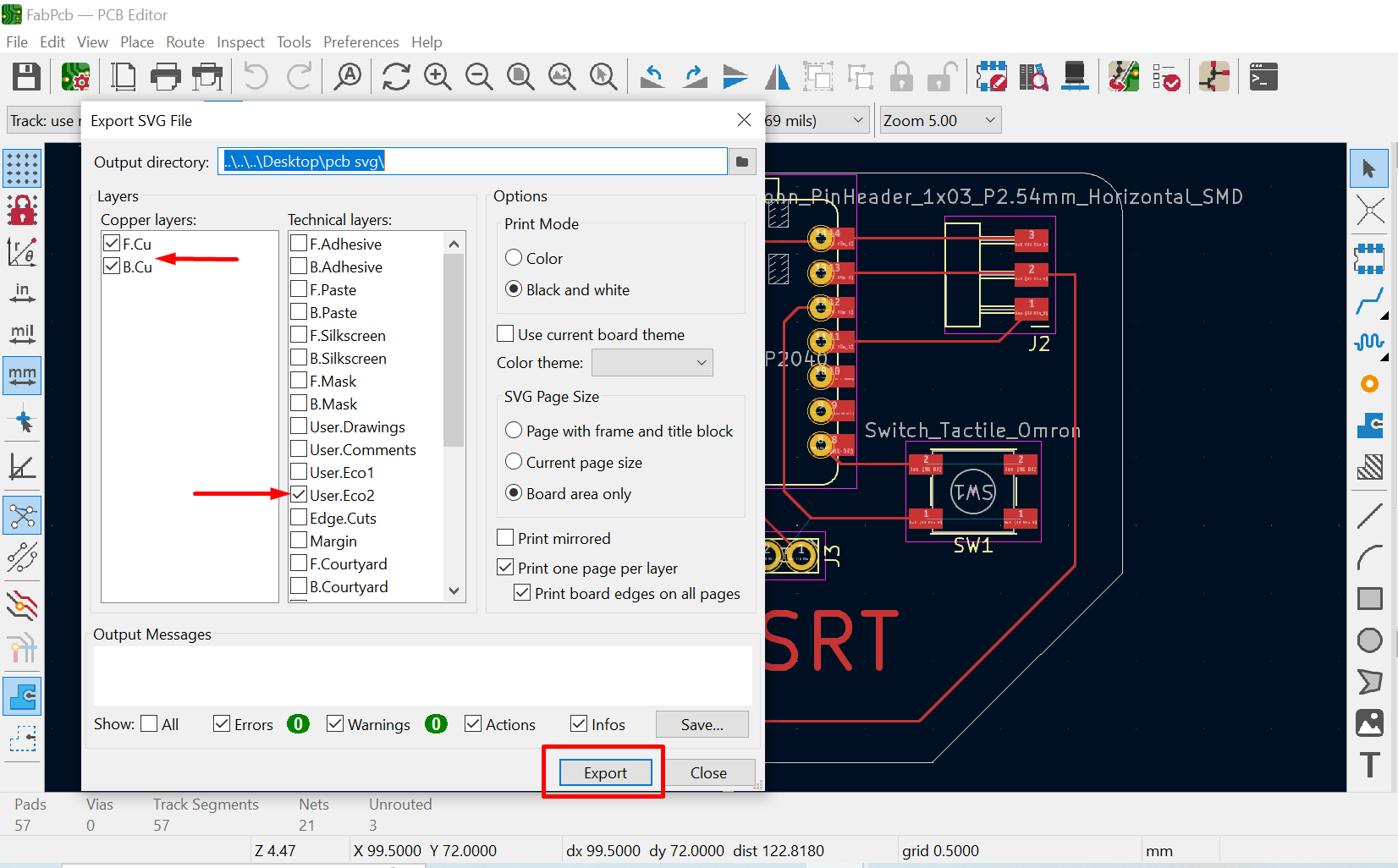
- SVG File for MODs CE
- Go to file >> then Export>> SVG format
- A new Tab will appearead select the layer that you want to print, mill

Tips:
- Follow a consistent naming convention for nets and components.
- Use libraries with pre-defined footprints for common components.
- Start with simpler designs and gradually progress to more complex ones.
- There are many online resources and tutorials available for learning KiCad.
By following these steps, you can design your PCB layout in KiCad and generate the necessary files for PCB manufacturing. Remember, practice and exploration are key to mastering KiCad's functionalities.
Reference Files
- Trace file click here
- Cutting Edge file click here
- KiCad file click here