
Week 9: Output Devices
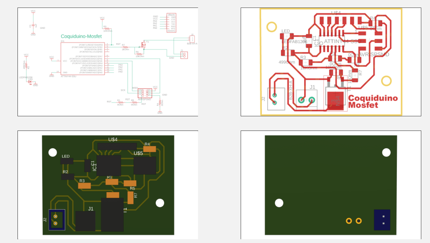
This week's assignment involves utilizing an output device on a board designed by myself. My primary objective is to develop the electronics for the final project. Consequently, the chosen board should have the capability to control two stepper motors and a solenoid. Therefore, I opted to design a board featuring an ATTiny44 microcontroller and an H-Bridge to effectively regulate the power of the solenoid using PWM.
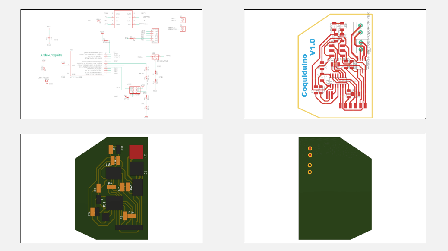
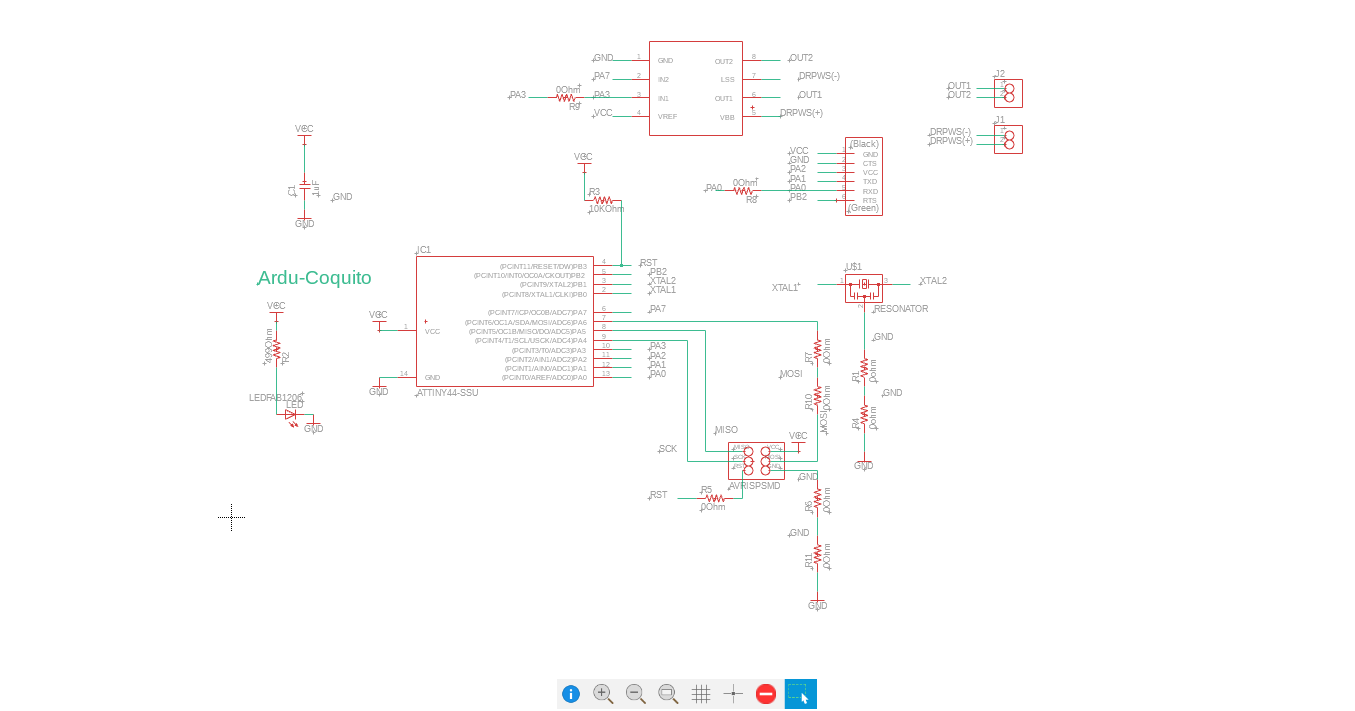
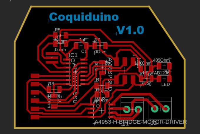
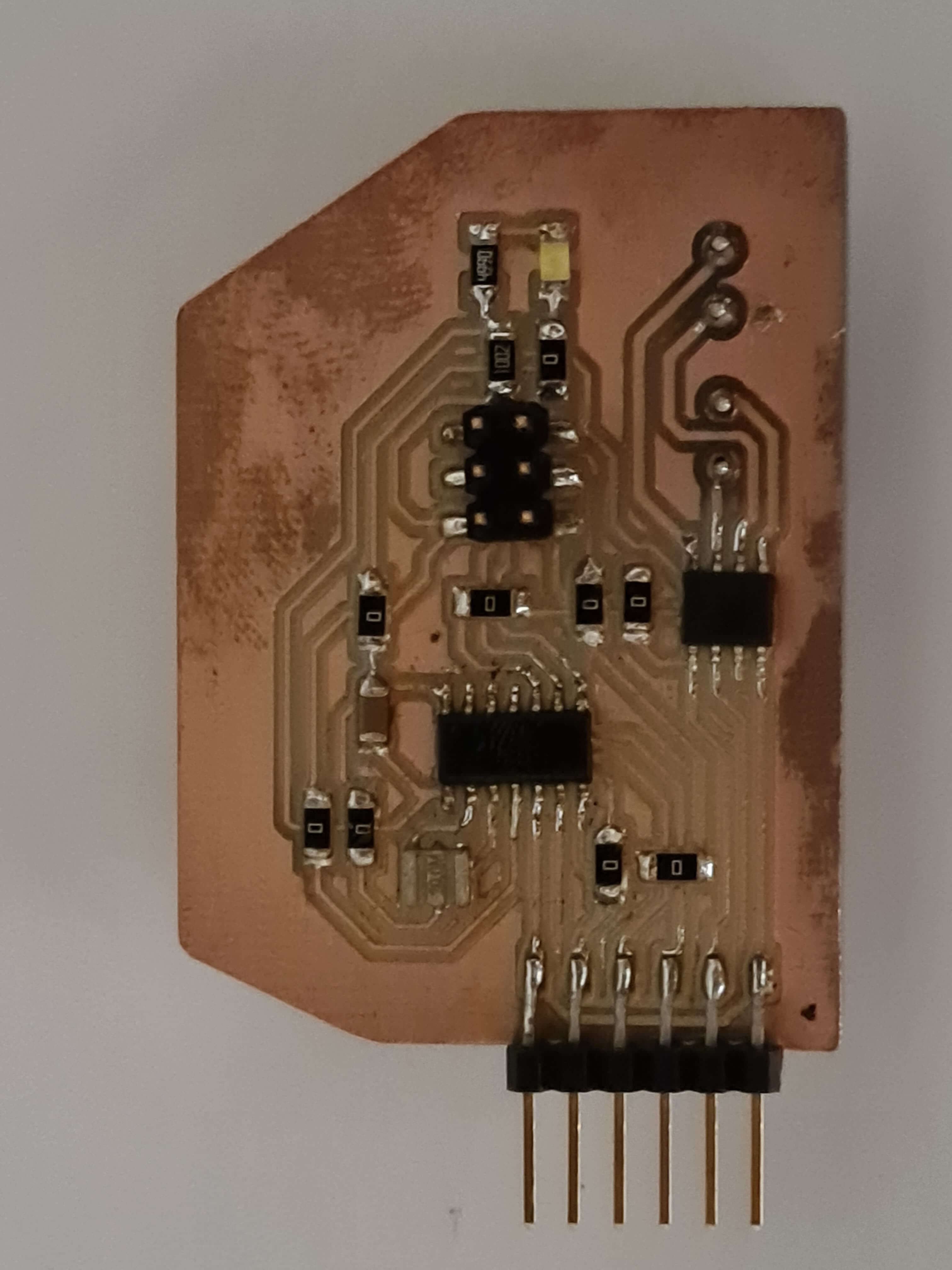
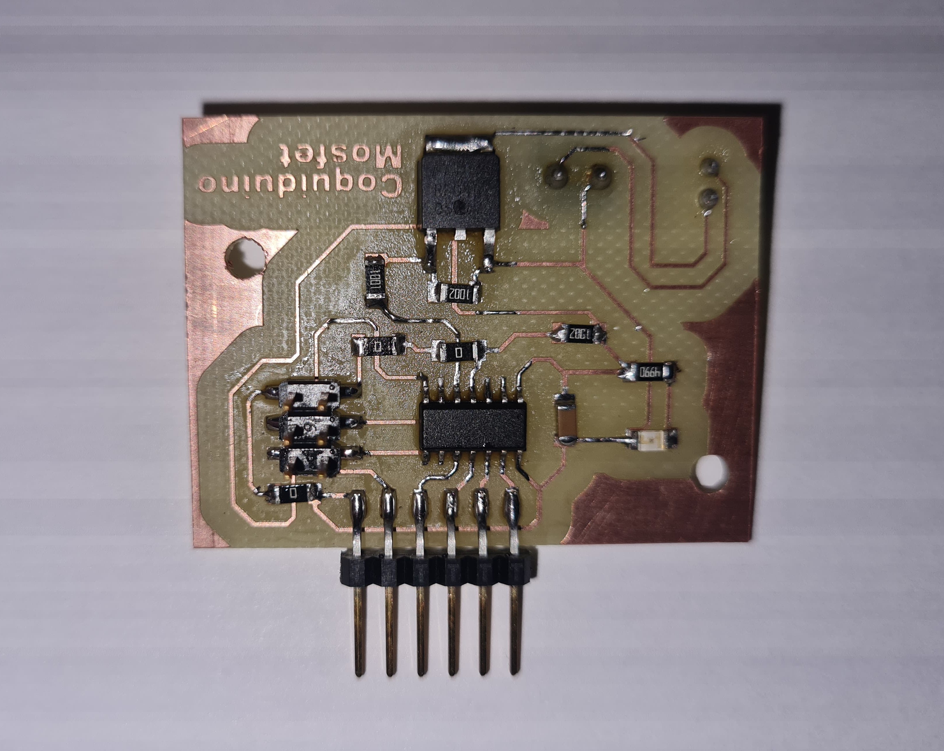
For the board design, it was crucial to consider the power devices needed to control the solenoid, as it operates within a voltage range of 5V to 7V. The voltage variation allows for adjusting the solenoid's force. Therefore, a component like a MOSFET, SSR, or H-Bridge was required. I decided to use an H-Bridge to control the solenoid. However, the correct choice would have been to apply a MOSFET, as the solenoid does not require reverse polarity since it is a simple coil. The components utilized for this electronic board include: A4953 H-Bridge, 1uF Capacitor, White LED accompanied by a 499 Ohm resistor to indicate the board's power status, 10Kohm resistor for the microcontroller's Reset pin, 20MHz external clock, Pin Header (3*2) for SPI communication, and additional Input/Output ports to utilize all pins.
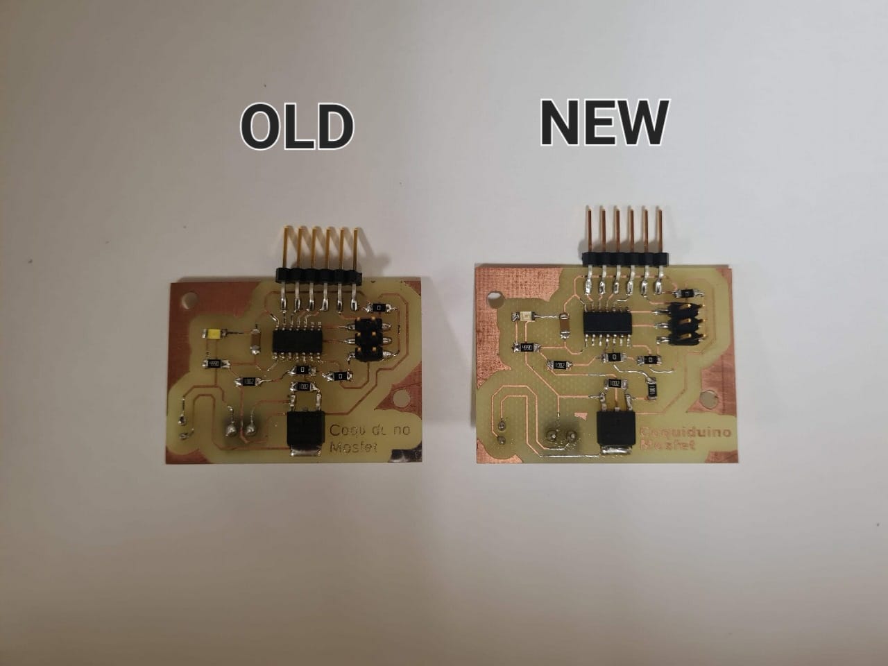
For some reason, the new board isn't allowing me to flash code onto it. Additionally, while the H-bridge is functional, it isn't ideal for this application due to its extra feature for inverting direction. Therefore, a MOSFET is the better choice for PWM output control.
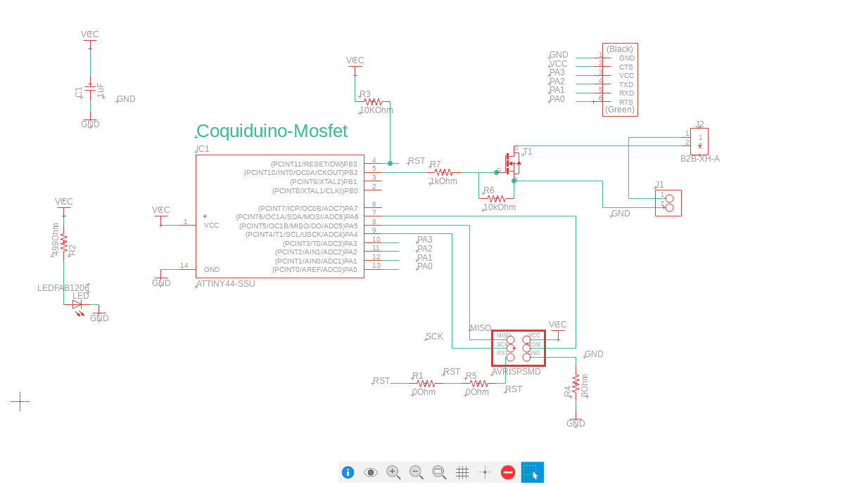
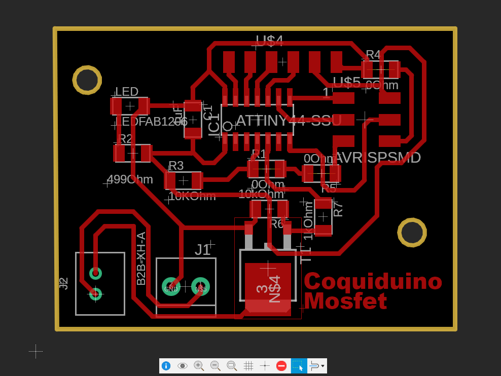
My first iteration of the new design encountered an issue related to the type of MOSFET used. I incorrectly assumed the MOSFET functioned as a simple switch, not taking into account the various types available. Specifically, I used an N-MOSFET, which operates by interrupting the connection to the GND pin. In my initial design, I mistakenly configured it to cut the positive side, resulting in the MOSFET not activating. In the second iteration, I correctly connected the MOSFET, ensuring it interrupted the ground connection, and it functioned very well!
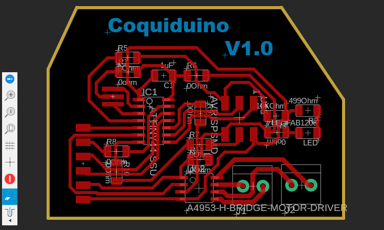
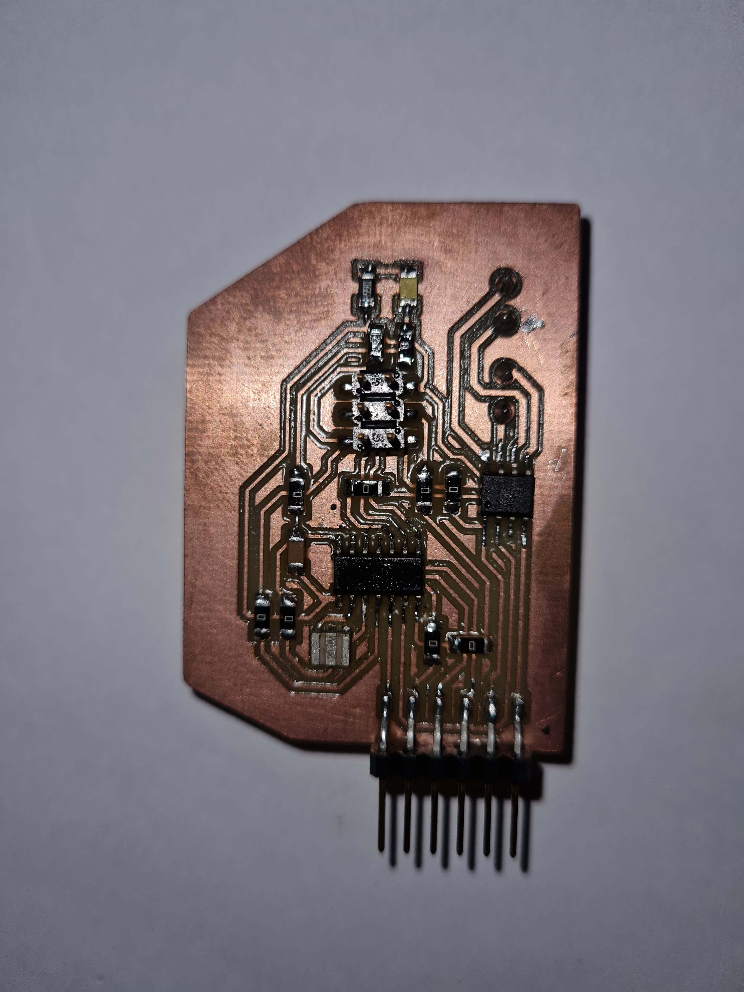
Additionally, I noticed that the text for the board name was too skinny and hard to read. To improve fabrication and visibility, I changed the font and increased the size of the text. These adjustments made the board name clearer and easier to read.
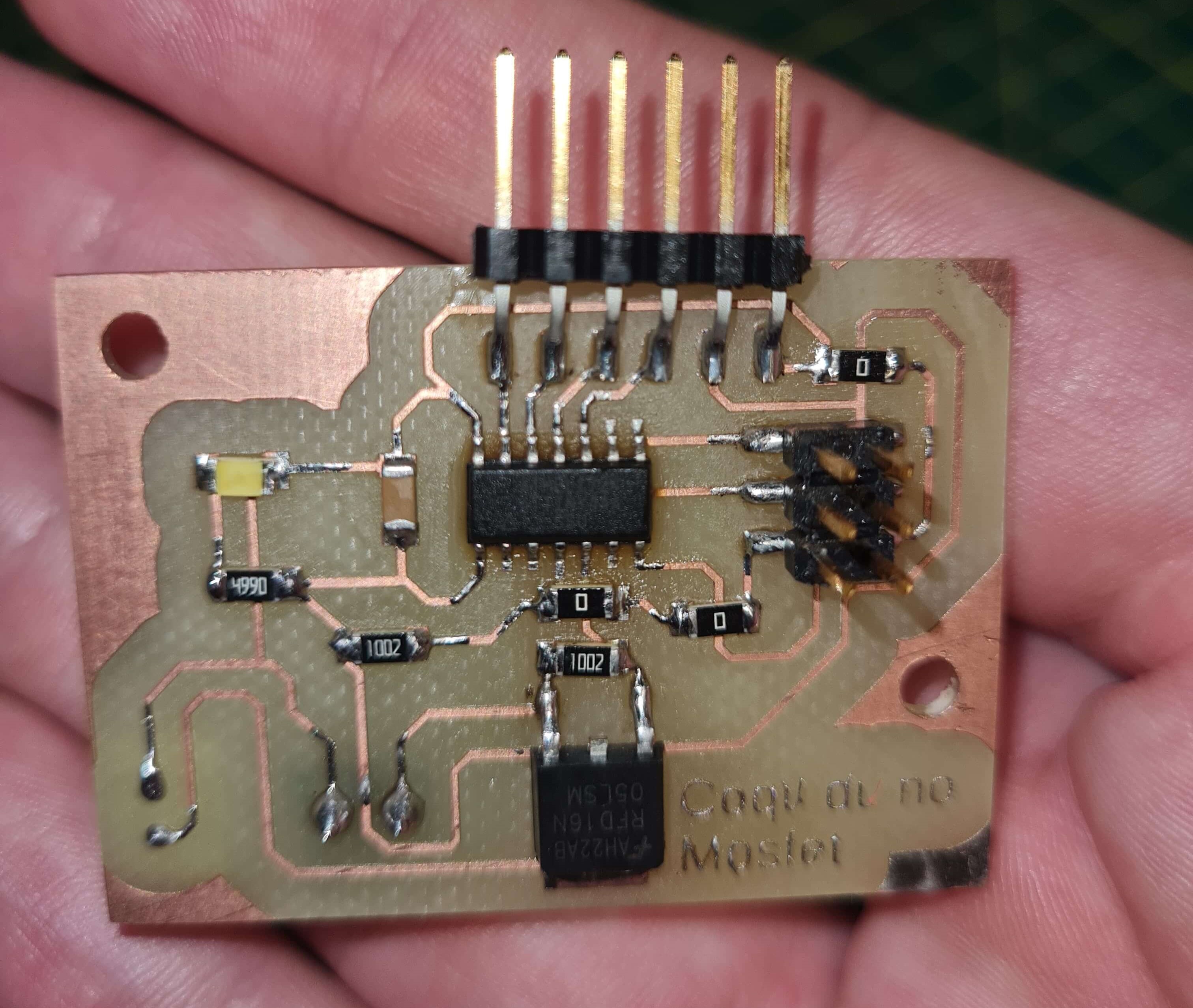
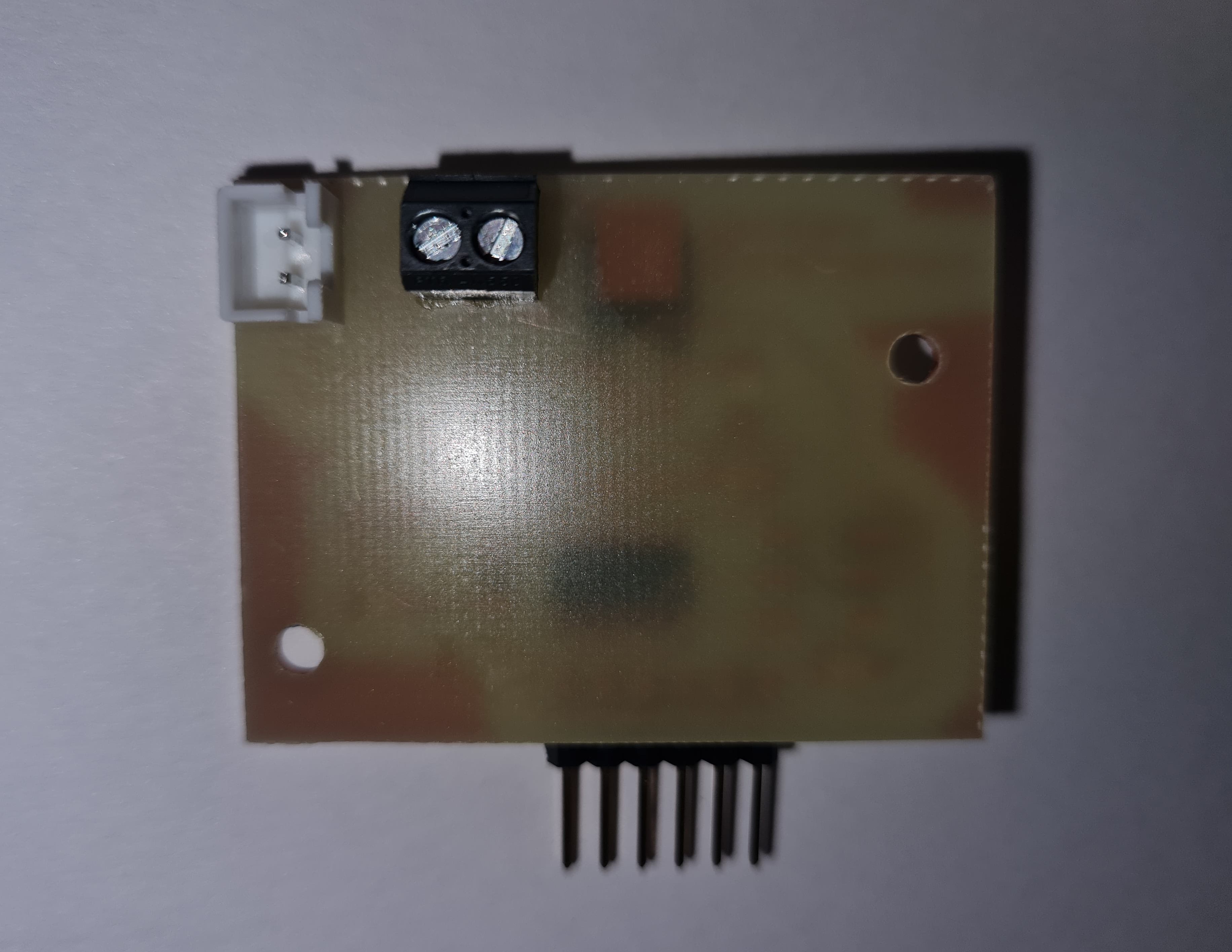
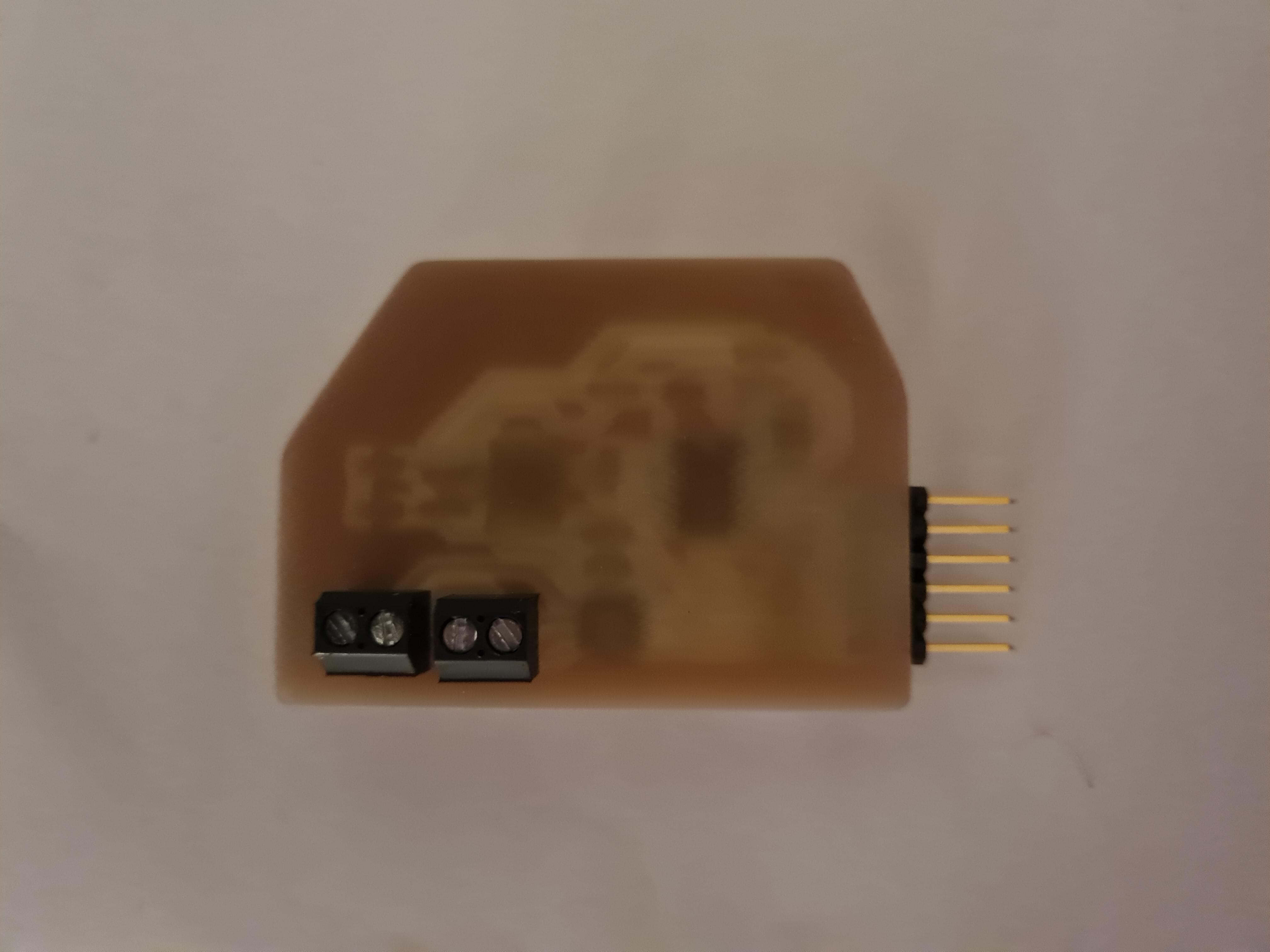
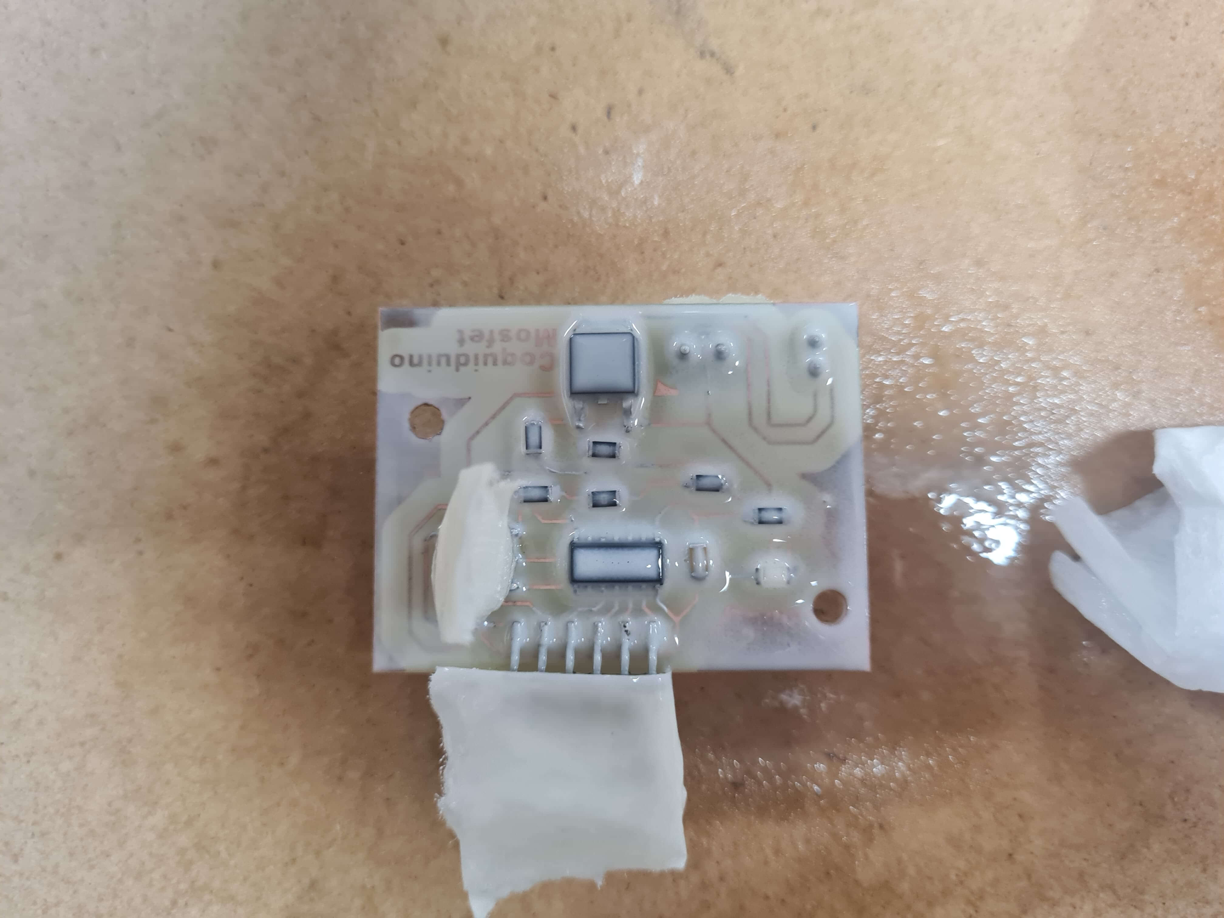
I decided to coat the final PCB with a spray varnish specifically designed for PCBs. This coating helps protect the traces and pads from shorts, dust, and humid environments. It was my first time coating a PCB, and I applied the coating a bit too thickly. For future coatings, I plan to apply a maximum of three light coats to ensure better protection without over-application.
Additionally, I protected the pins because an uncoated surface is necessary to maintain continuity and avoid interrupting the connection. I used masking tape to cover all the pin headers and connectors before applying the coating.

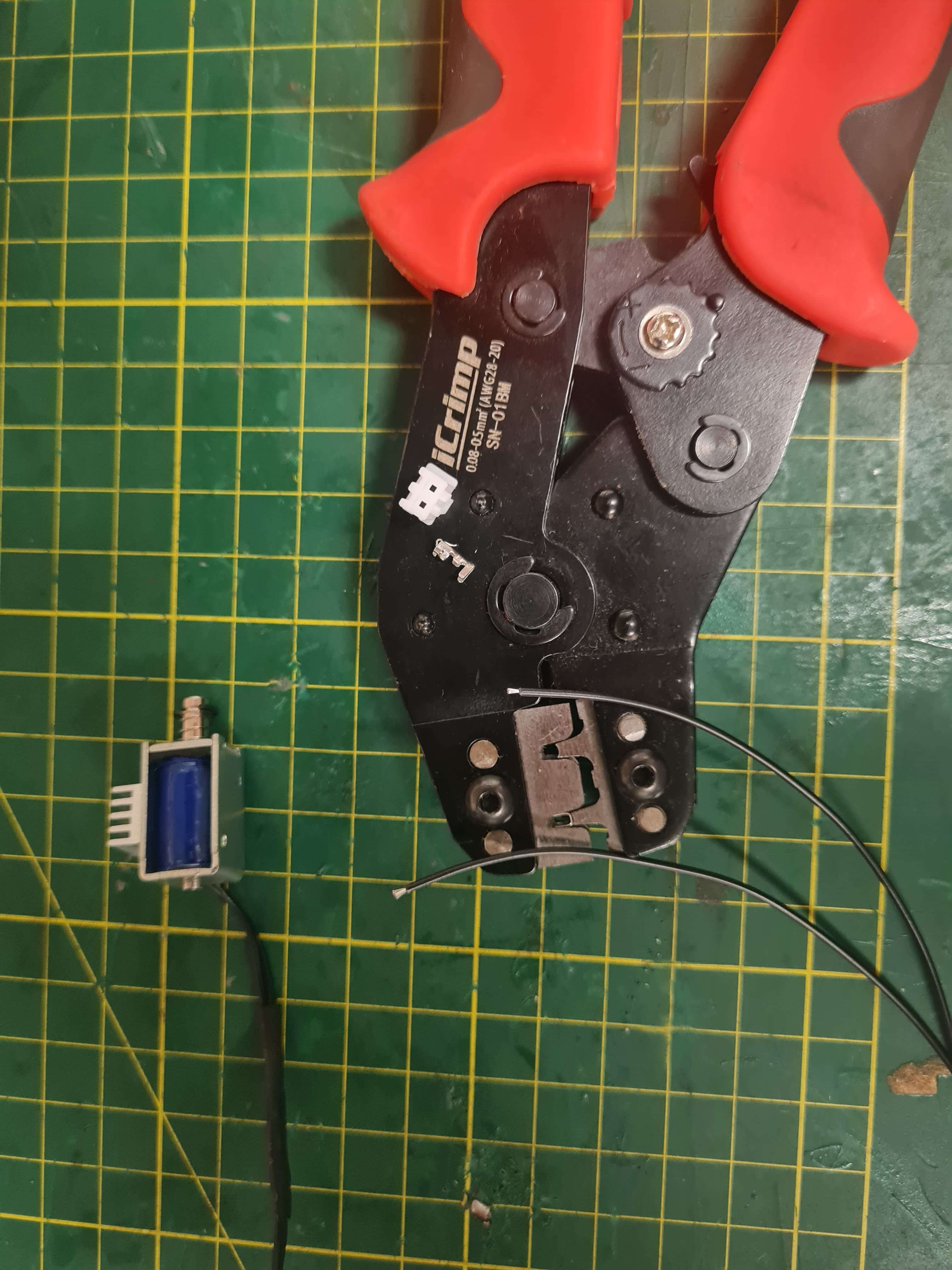
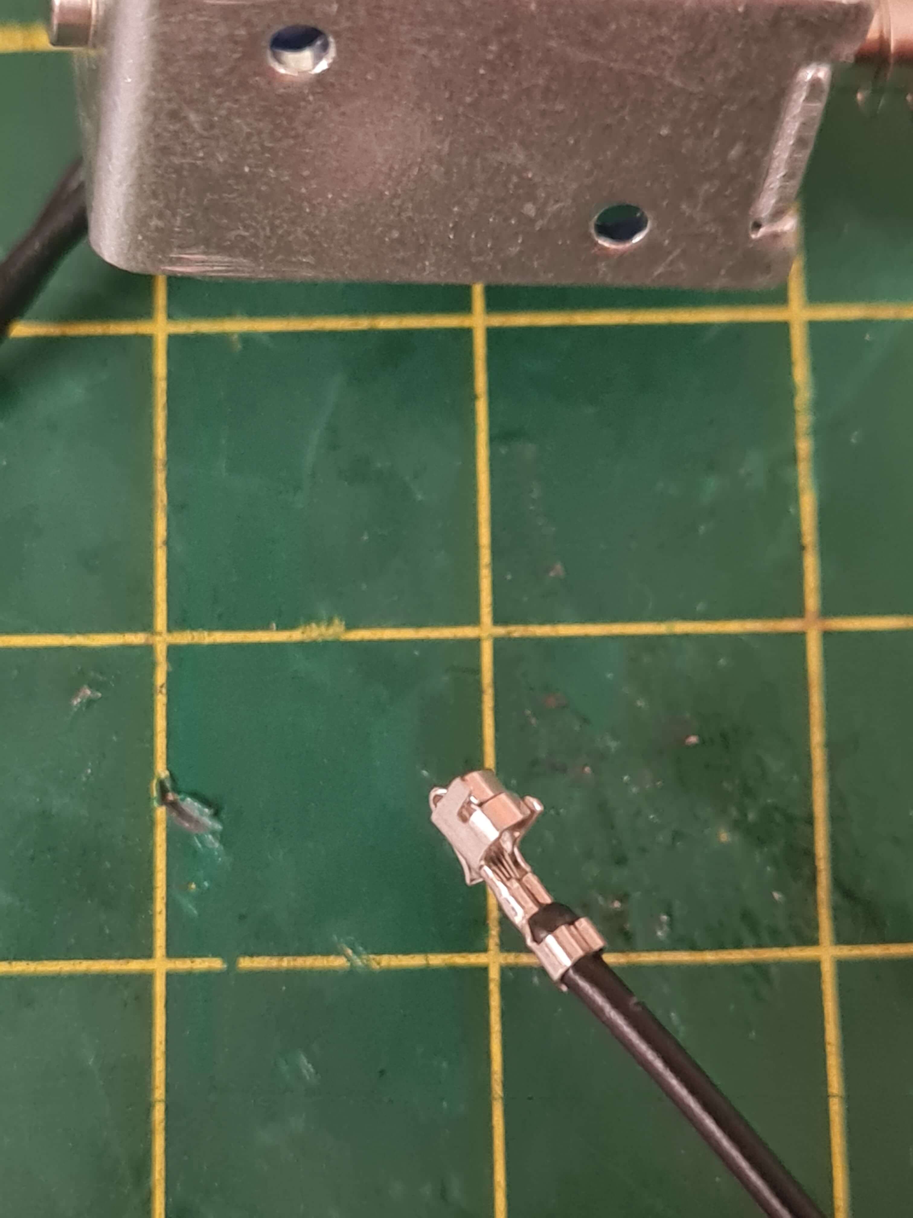
JST connectors are compact and versatile, making them ideal for various applications. They provide secure and reliable connections with easy assembly. This is why I used them to connect the solenoid to the PCB board.
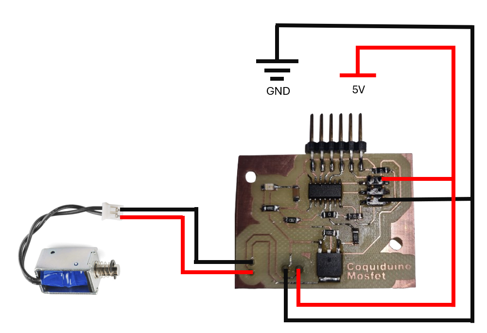
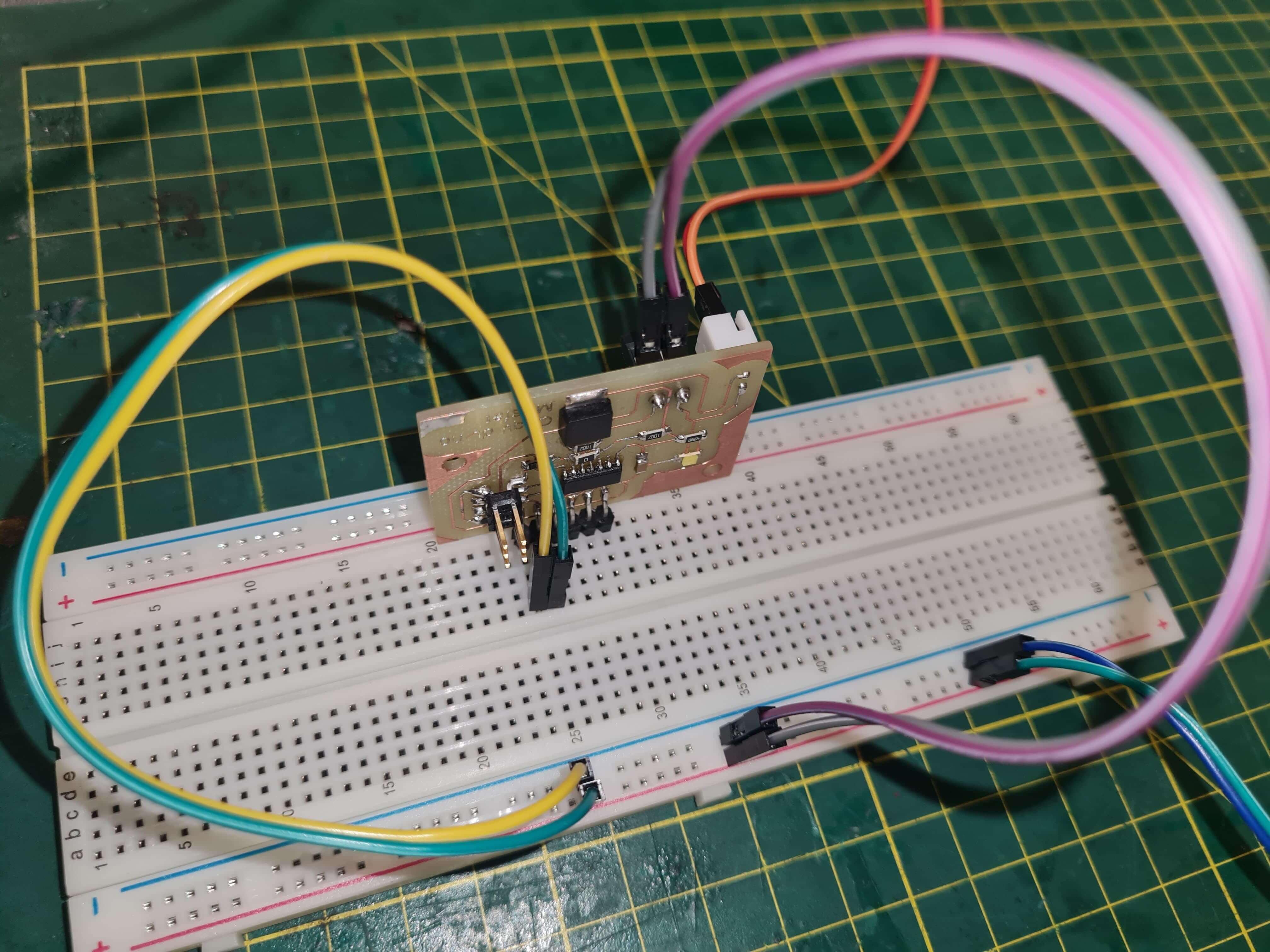
The Arduino code provided switches the solenoid from a LOW state to a HIGH state every 100 milliseconds, thereby testing the functionality of the MOSFET. The solenoid is connected to pin 8 of the microcontroller, which is configured as an output in the setup function. The loop function continuously toggles the solenoid on and off, with a 100-millisecond delay between each state change. This simple yet effective test ensures that the MOSFET operates correctly and can control the solenoid as intended.
    // Program Code: Attiny44 Solenoid On-Off //

    // Written by: Jorge Suarez de Freitas //


    // Define pin numbers for components
    int Solenoid = 8

    // Setup function: runs once when the program starts
    void setup() {
      // put your setup code here, to run once:

    // Set pin modes (Input or Output)
    pinMode(Solenoid,OUTPUT);
    }

    void loop() {
      // put your main code here, to run repeatedly:

    digitalWrite(Solenoid,HIGH); //Turn On Solenoid
    delay(100);
    digitalWrite(Solenoid,LOW); //Turn Off Solenoid
    delay(100);
    }
This week groupal assigment I've learned the critical importance of measuring the current draw of the solenoid coil before selecting the appropriate MOSFET specifications. This step is essential for ensuring that the chosen components can handle the electrical demands of the solenoid effectively.
By prioritizing this measurement early in the project, I can make informed decisions that optimize performance and reliability. This experience has underscored the significance of thorough initial testing and analysis in electronic design, setting a strong foundation for successful project implementation. Selecting the right component not only reduces costs but also enhances safety by ensuring compliance with the manufacturer's datasheet specifications. This approach mitigates risks associated with component overloading and improves overall project efficiency.