Week 7: Computer Controlled Machining
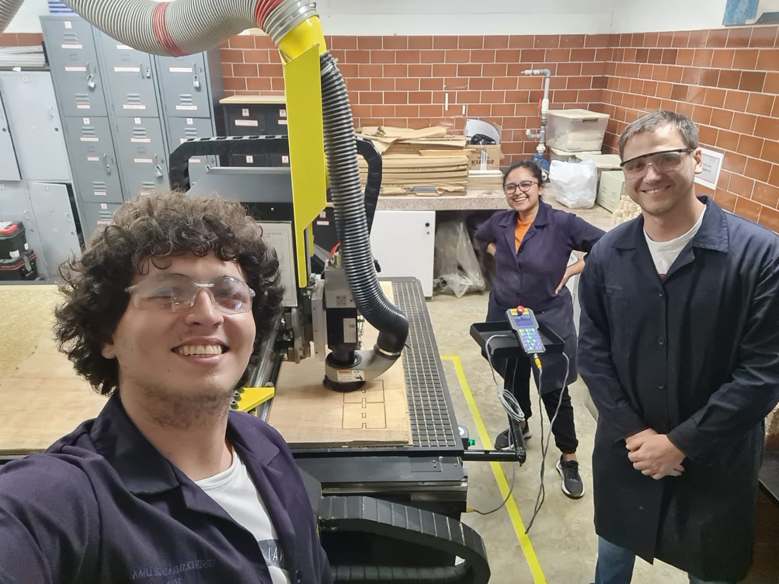
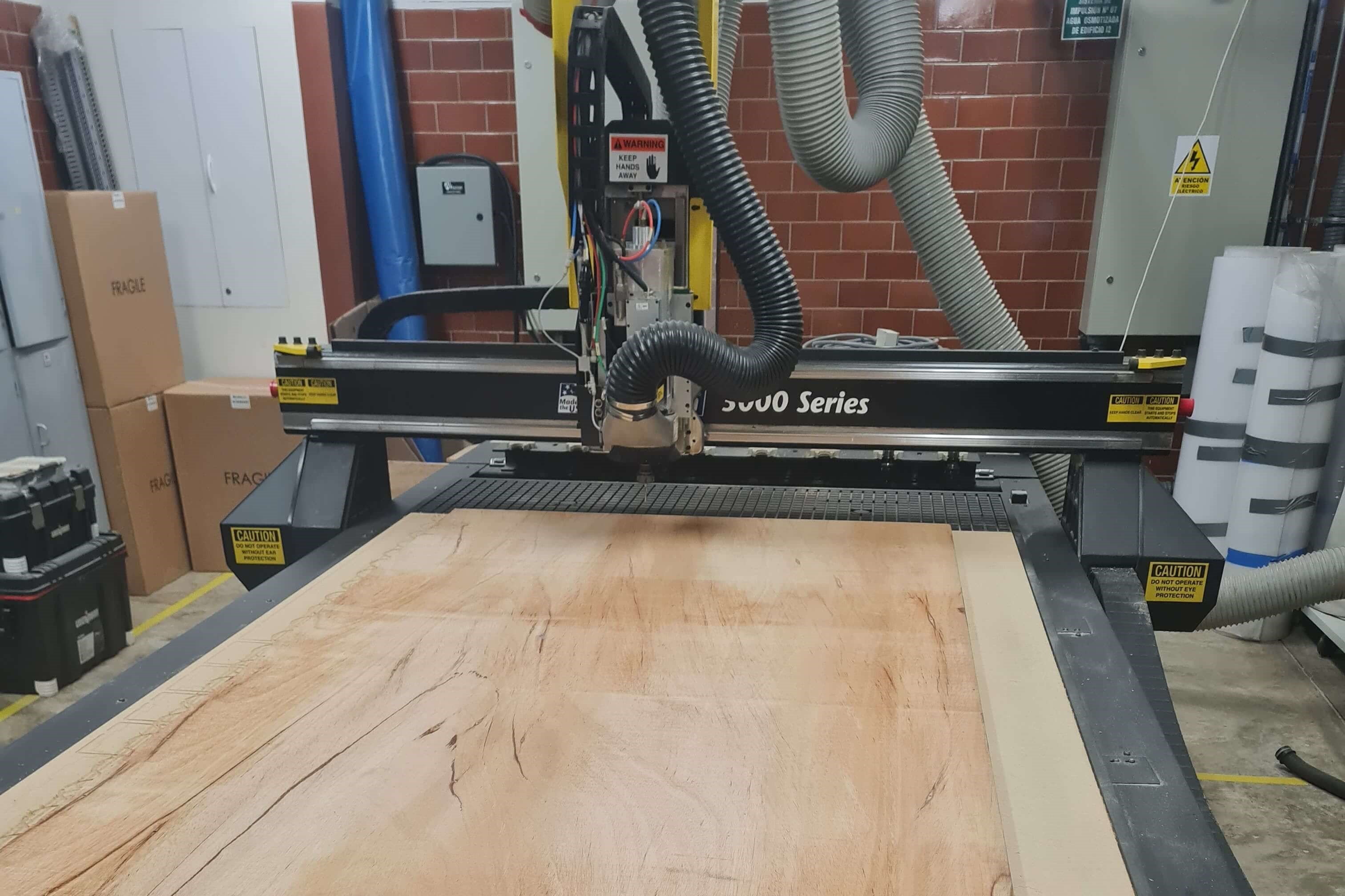
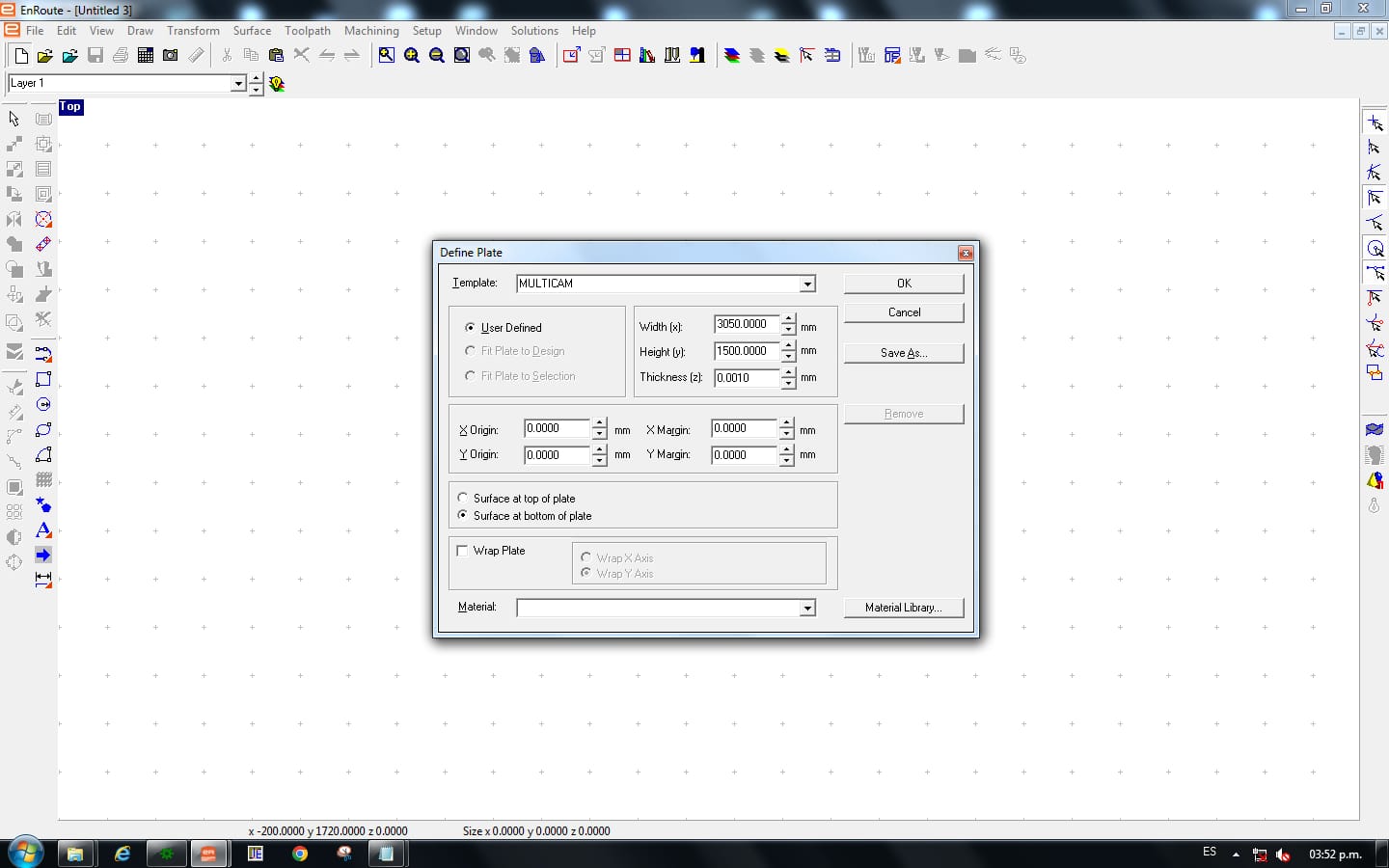
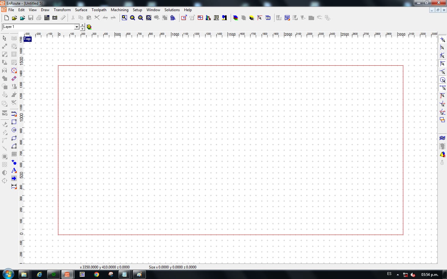
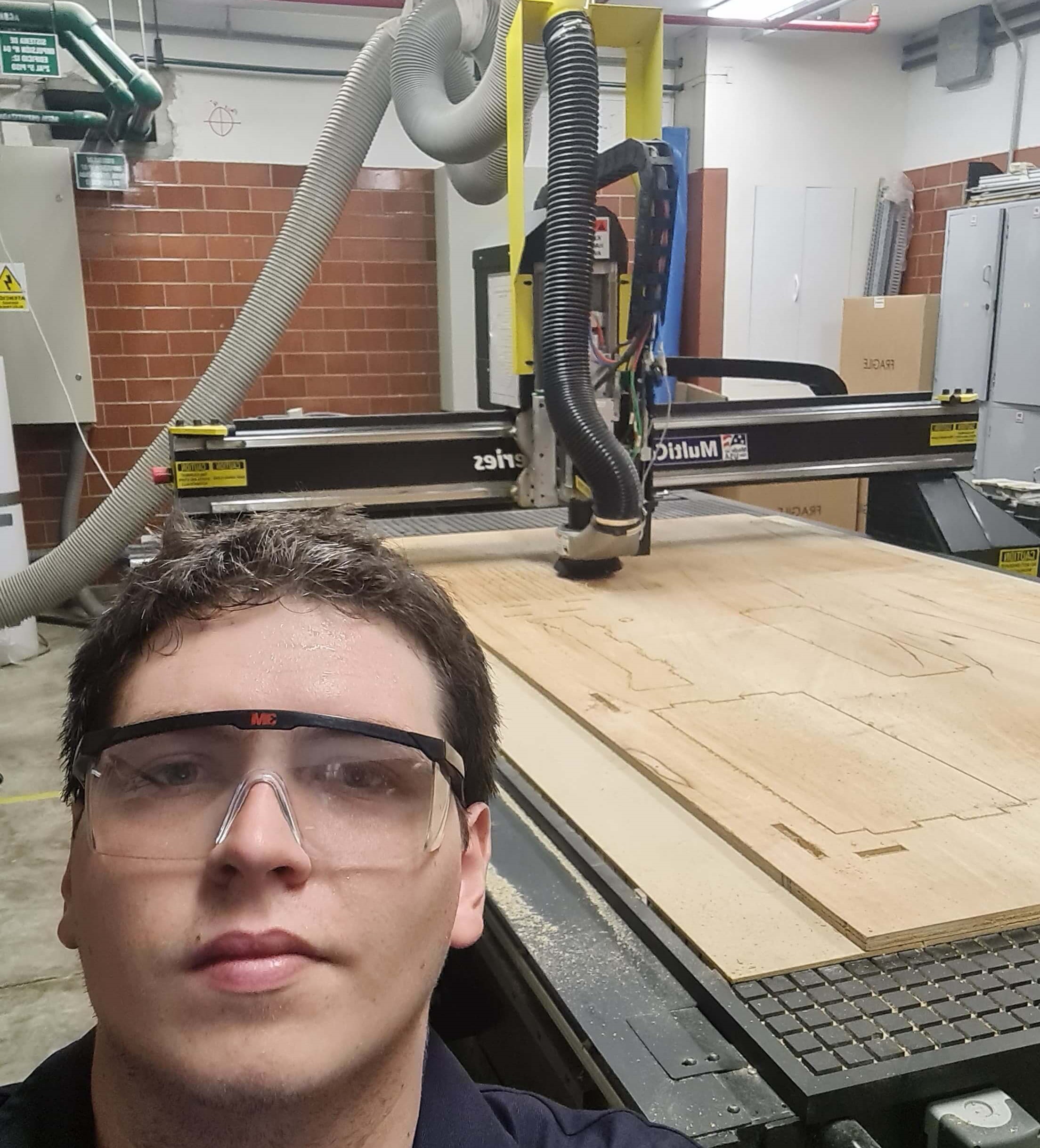
This week, I learned to operate a CNC router for furniture manufacturing. To achieve this, the furniture was designed using Inventor Professional. Glue isn't necessary for assembling the furniture as the joints are press-fit. The designs were then exported as .DXF files to Enroute, a software that generates G-code. The machine used was a MultiCam 3000 Series, it is router-type milling machine characterized by a short Z-axis stroke and a work platform measuring 1500mmx3050mm. This machine is designed for cutting flat sheets. The material used was a 18mm thick plywood sheet.
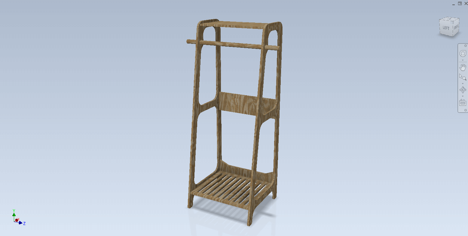
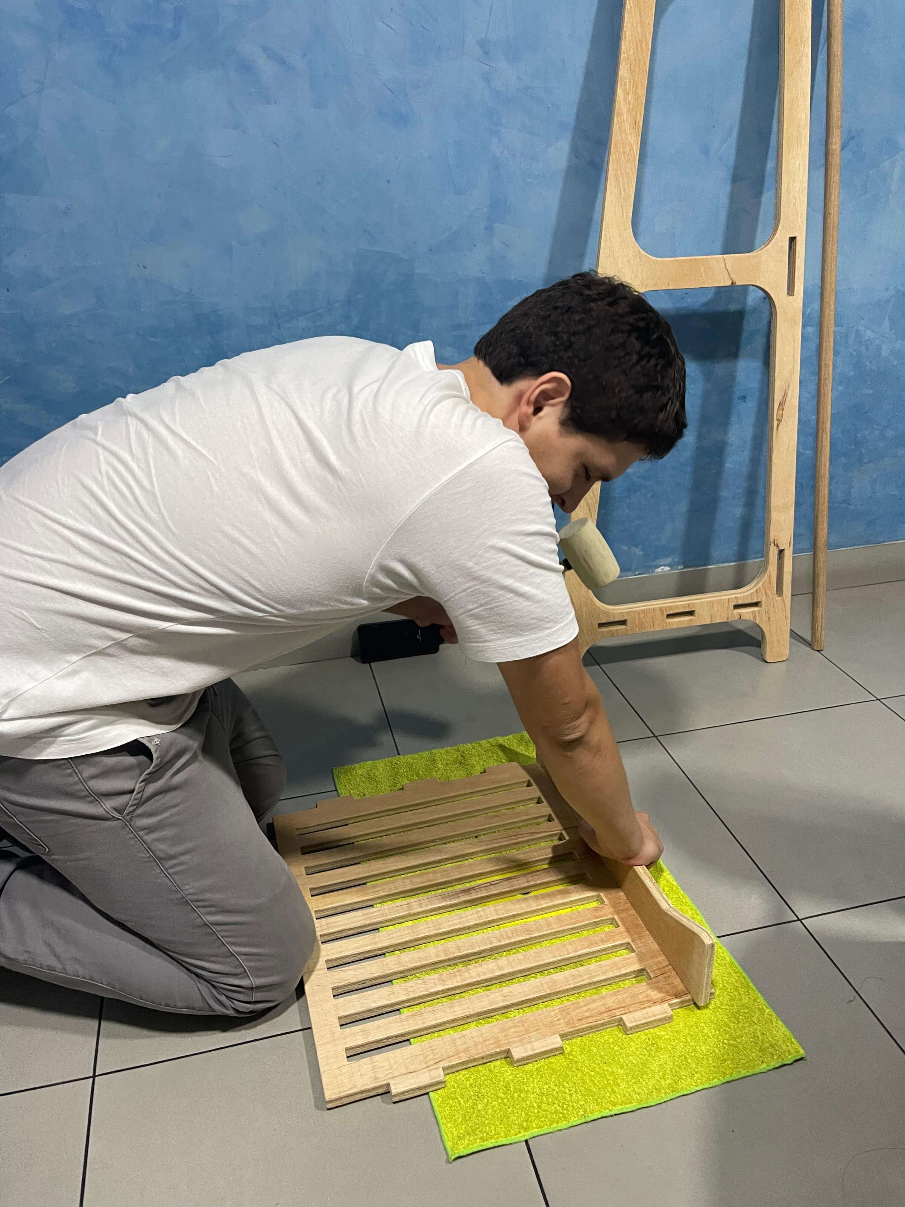
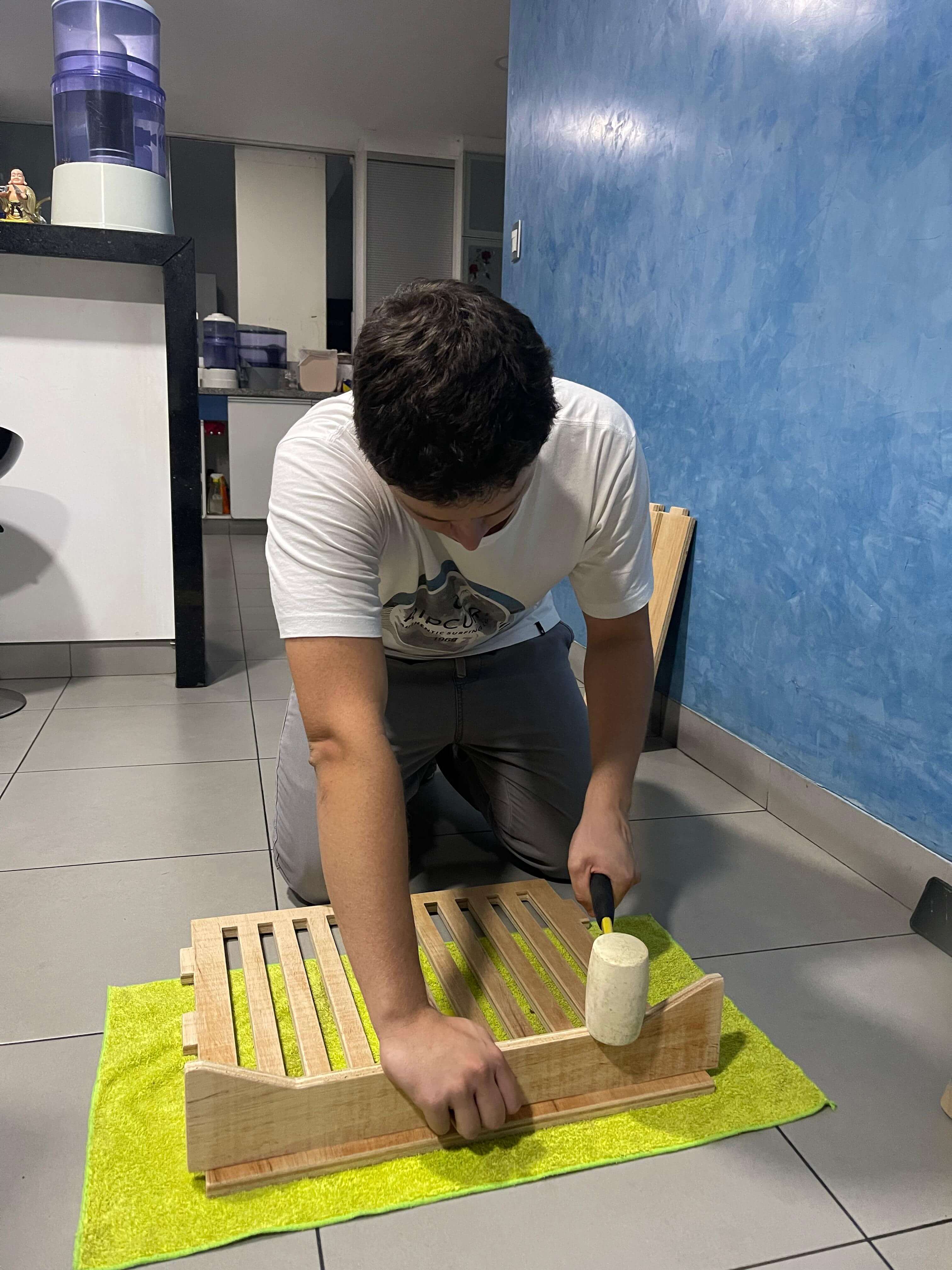
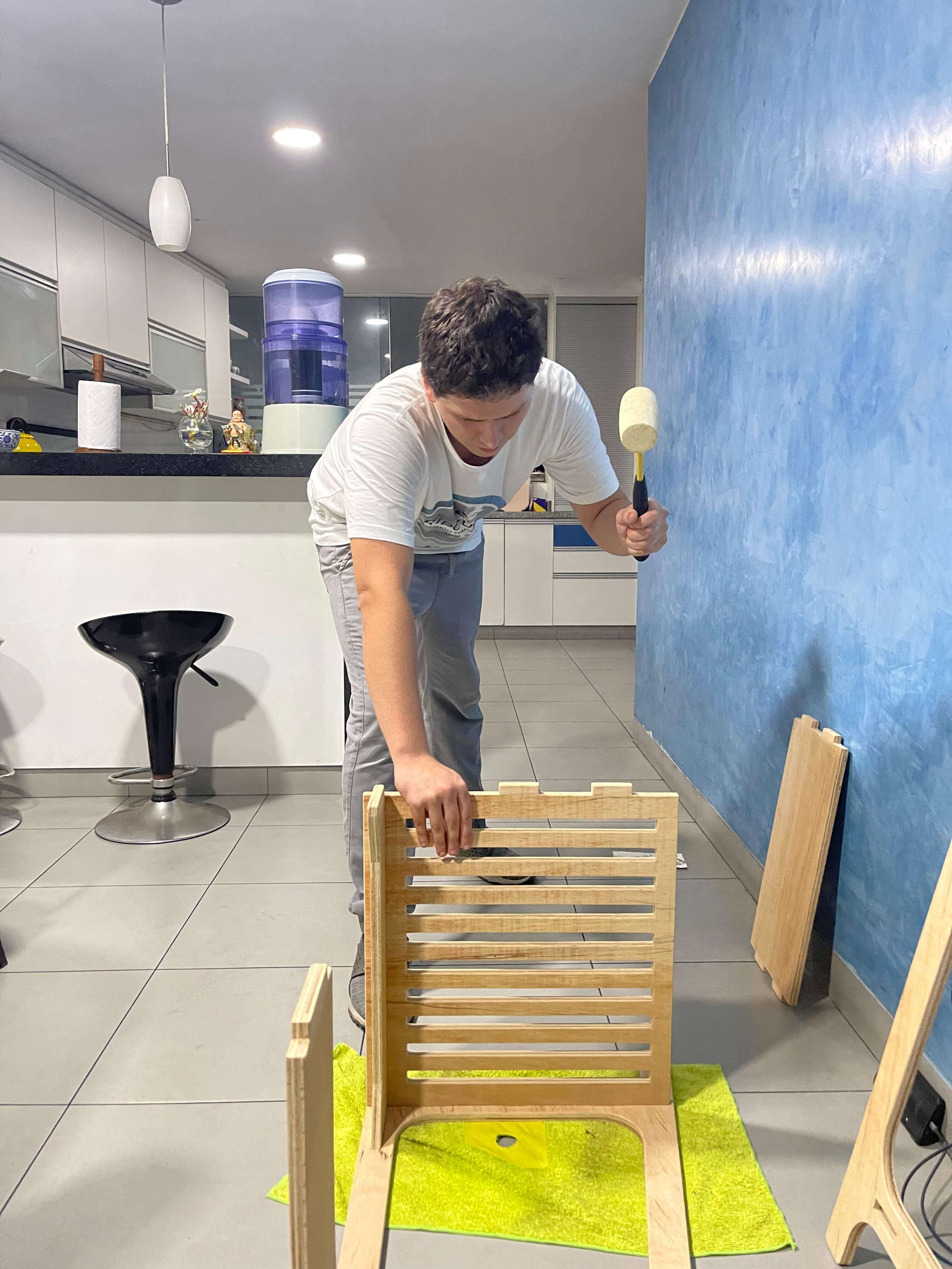
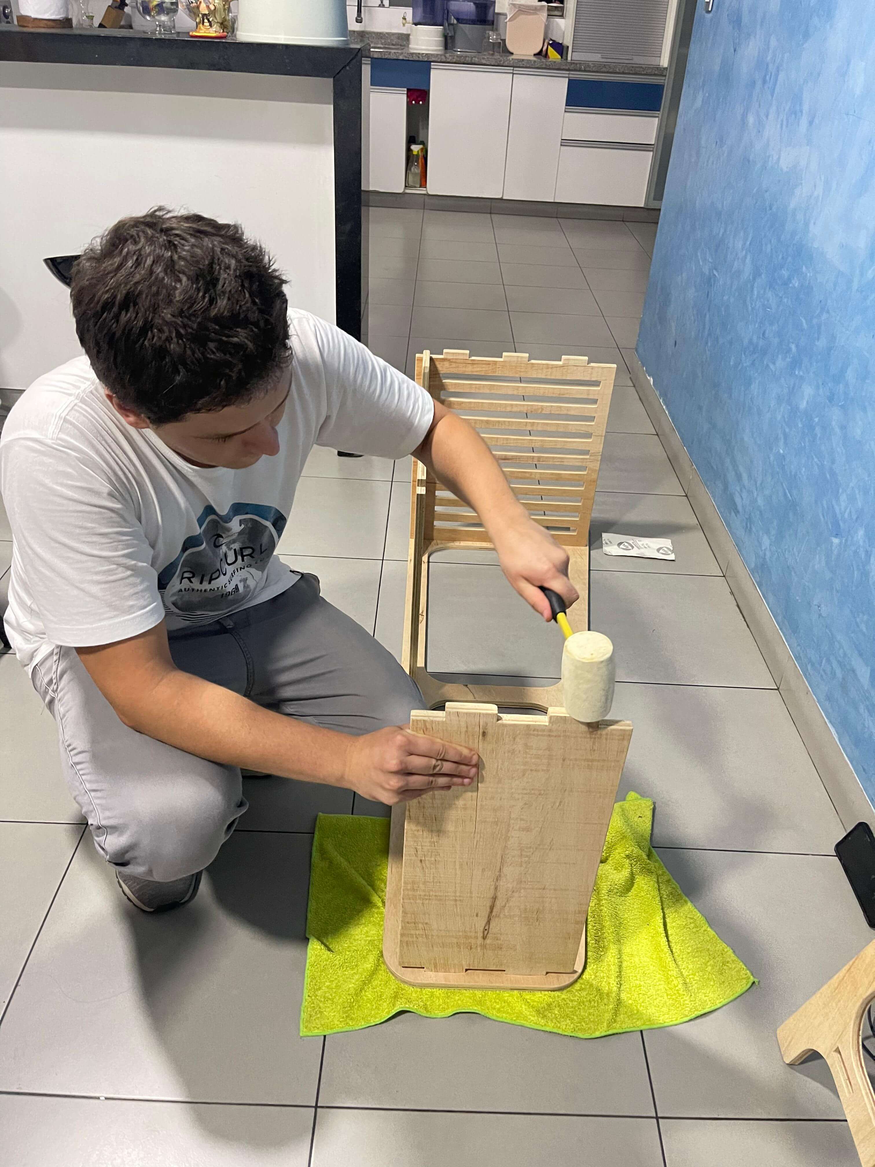
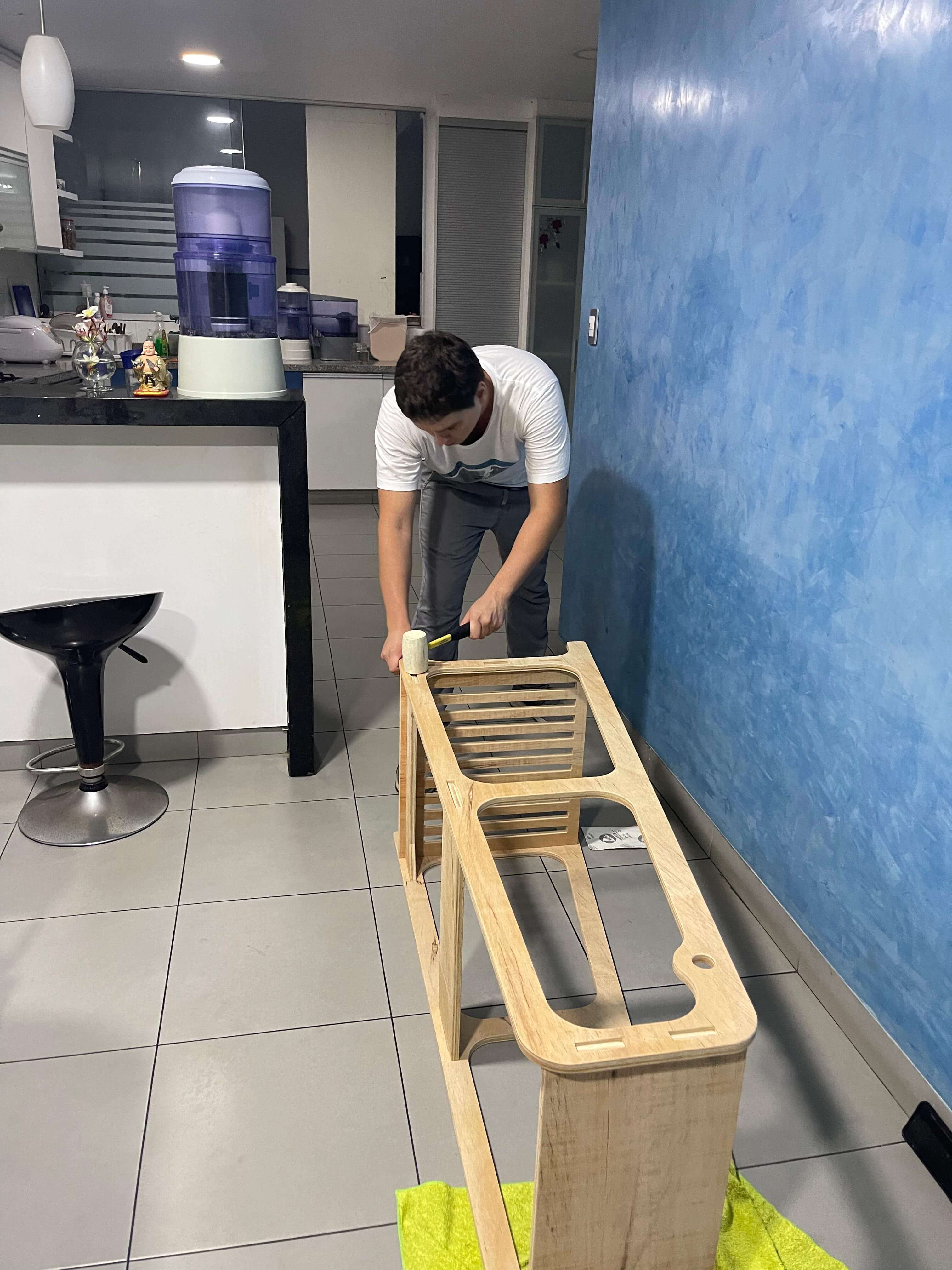
For the design, I have chosen to incorporate dog-bone joints for all the press-fit connections to minimize the time spent on sanding. The fit tolerance is 0.1mm for all the press-fit connections. The furniture piece is a "Clothing Display Rack" intended for my girlfriend, featuring a shoe rack at the bottom, a clothing rack in the middle, and a shelf on top.
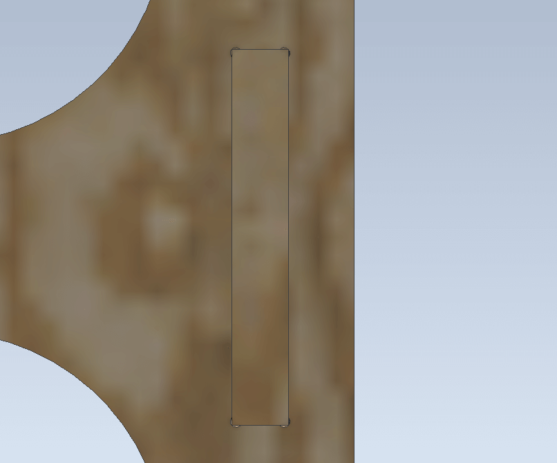
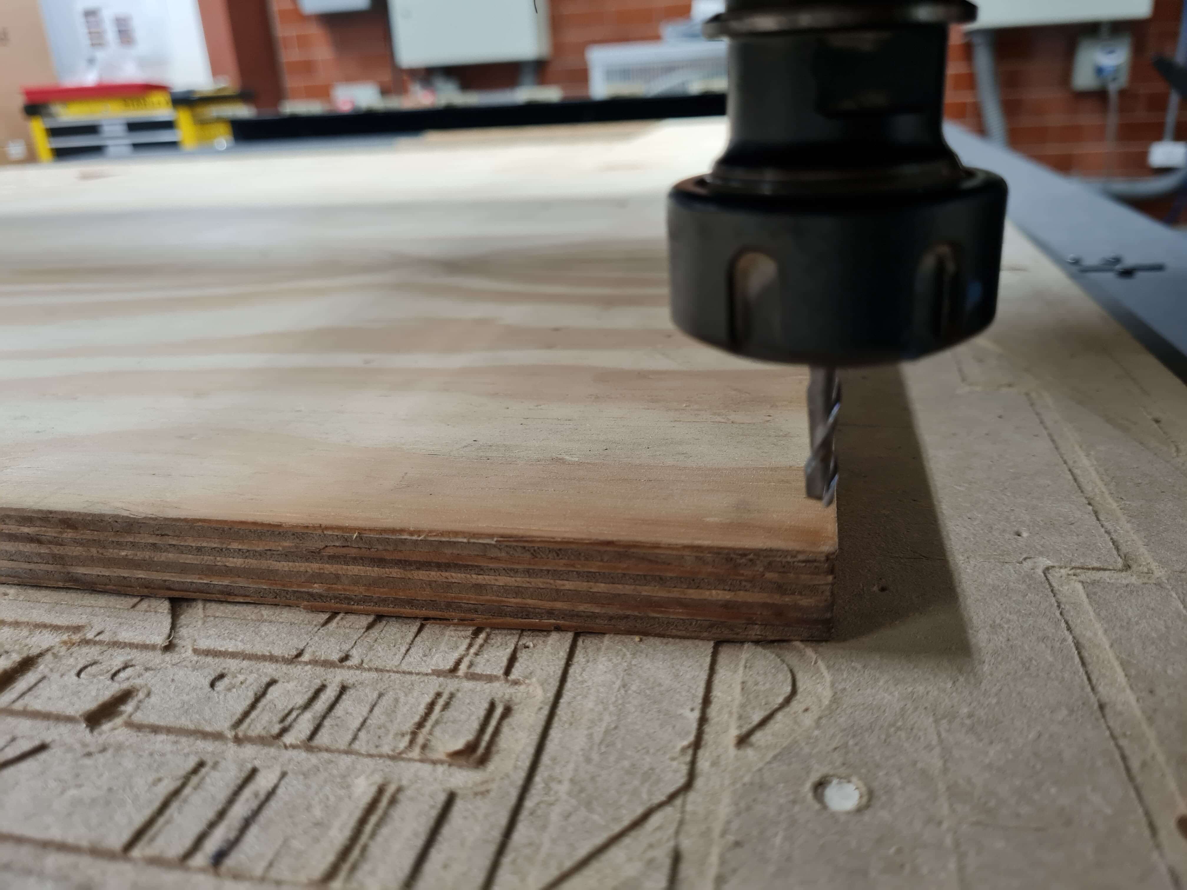
Nesting is the initial step in the CNC machining process where I manually arrange various parts to be cut from a sheet of material in the most efficient manner possible. The goal of nesting is to minimize waste and optimize the use of the available space on the sheet. This involves arranging the parts so they fit closely together, reducing the amount of scrap material left after cutting. For the milling process, I used a 1/8-inch flute end mill. To ensure the tool fits into the dog-bone joints, I modeled the joints with a 3.5mm diameter in Inventor Professional. This approach allows the tool to enter the joints accurately, ensuring efficiency in the machining process.
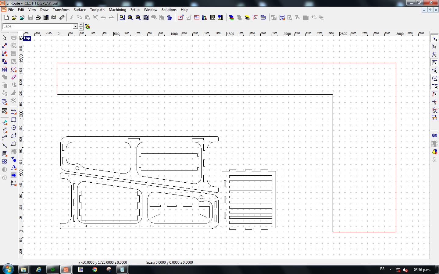
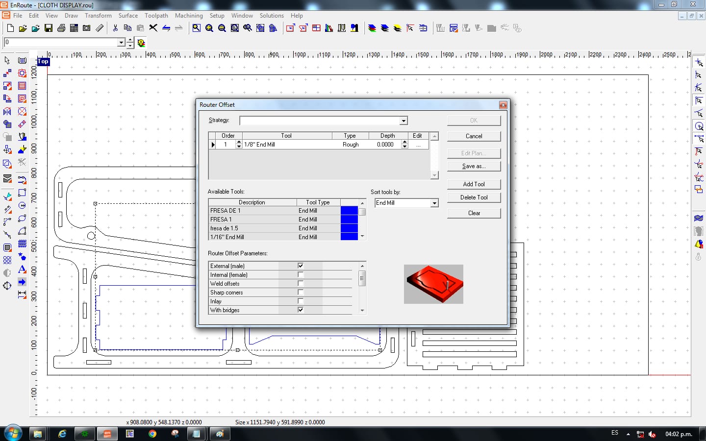
This type of design requires routing with a "Routing Offset" because it involves following a specific path while offsetting for the tool to cut the final pieces accurately. The software will follow the center of the path, accounting for the tool's diameter.
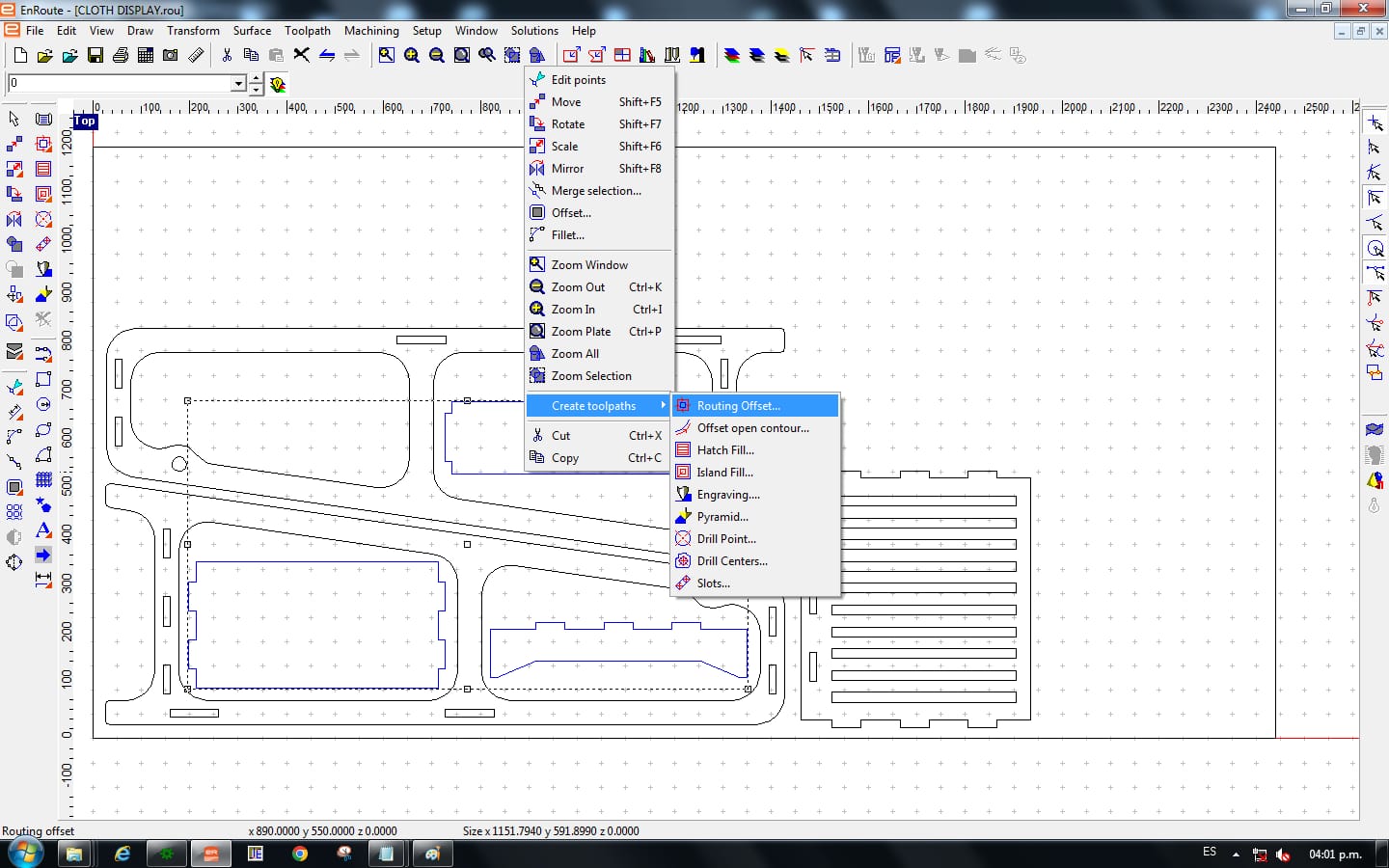
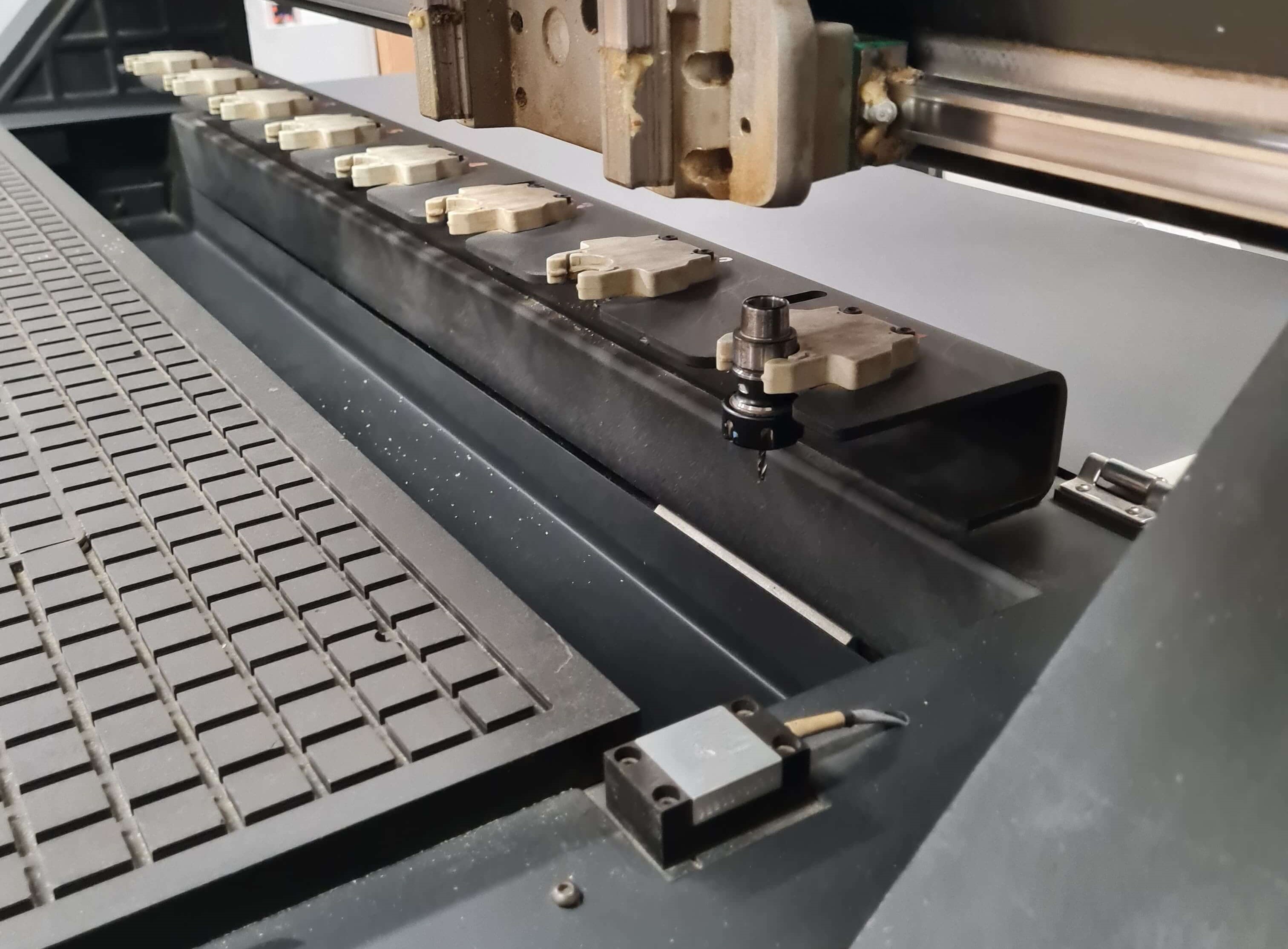
After the nesting process is completed, the next step is to set up the tool database. This involves inputting the specific details of the tools that will be used for cutting the parts. This includes information such as the type and size of the tool, the cutting speed and feed rates, and any other relevant parameters. Having an accurate tool database ensures that the CNC machine uses the correct tools and cutting parameters for each part, which is essential for achieving high-quality results.
The FABLAB Ulima has a comprehensive tool database saved in the EnRoute software, detailing all available tools. For this job, I selected the 1/8-inch two-flute spiral end mill from this database. I then configured the feeds and speeds to ensure high-quality routing and machining.
The cutting parameters are:
To achieve high-quality results and prevent crashes during the milling process, it is necessary to prioritize milling the inner geometries before the outer ones. The rationale behind this approach is that once the outer pieces are cut, they can move if they are not securely mounted to the working platform. By milling the inner pieces first, you ensure that the material remains stable throughout the process. This step is crucial for maintaining precision and avoiding any potential movement that could compromise the final outcome.
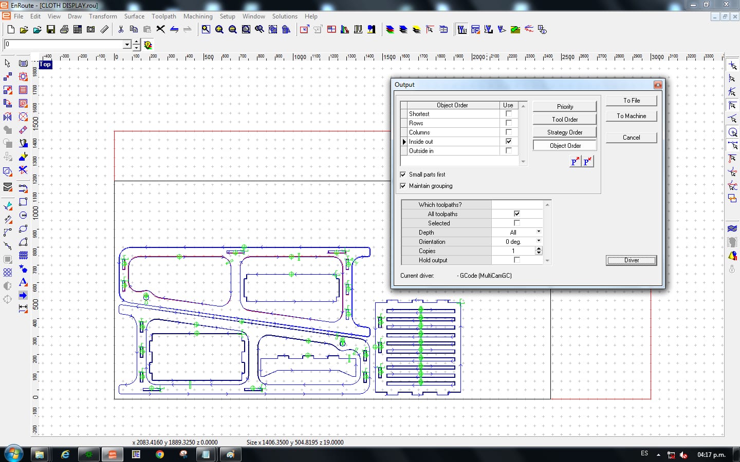
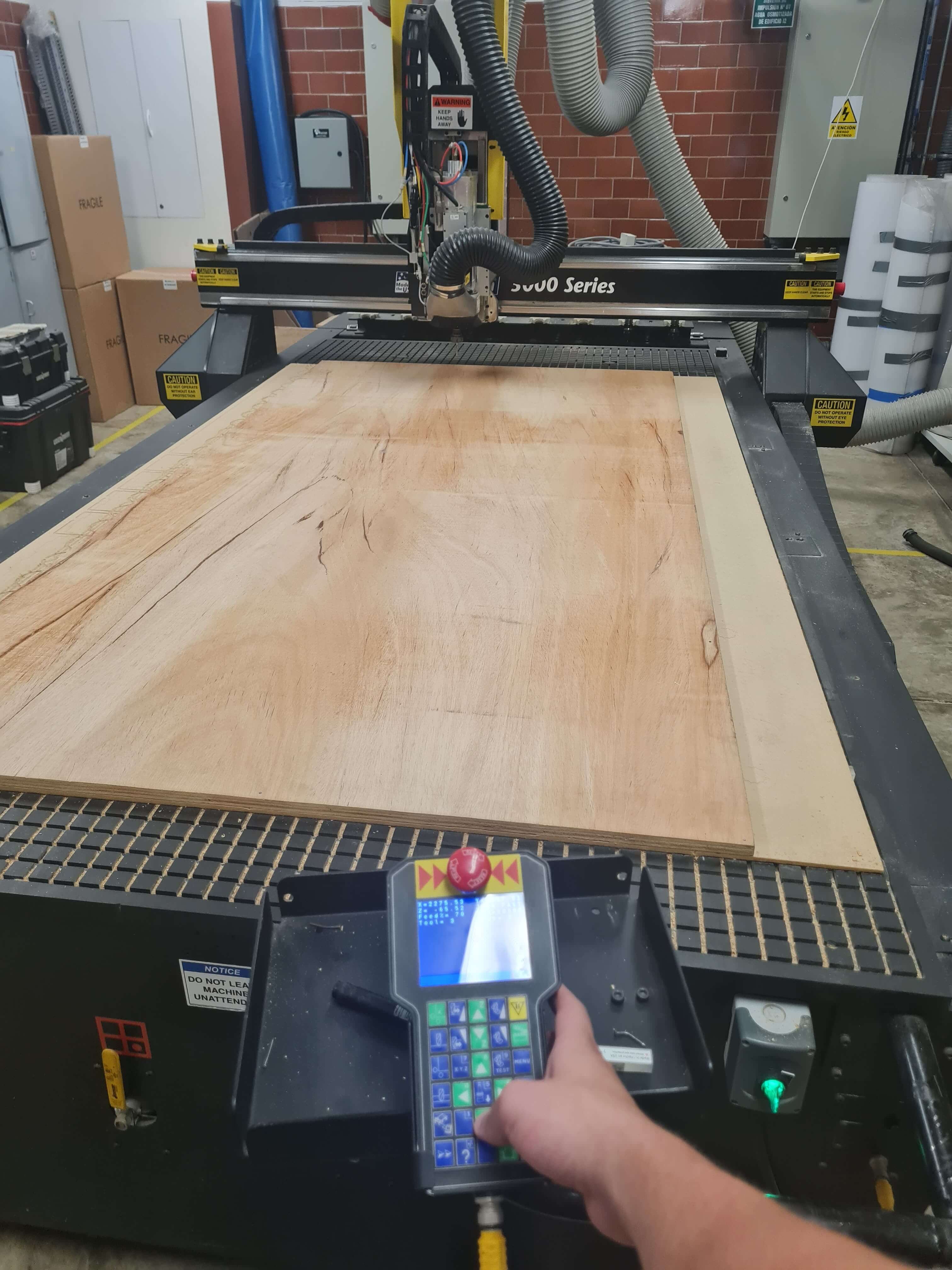
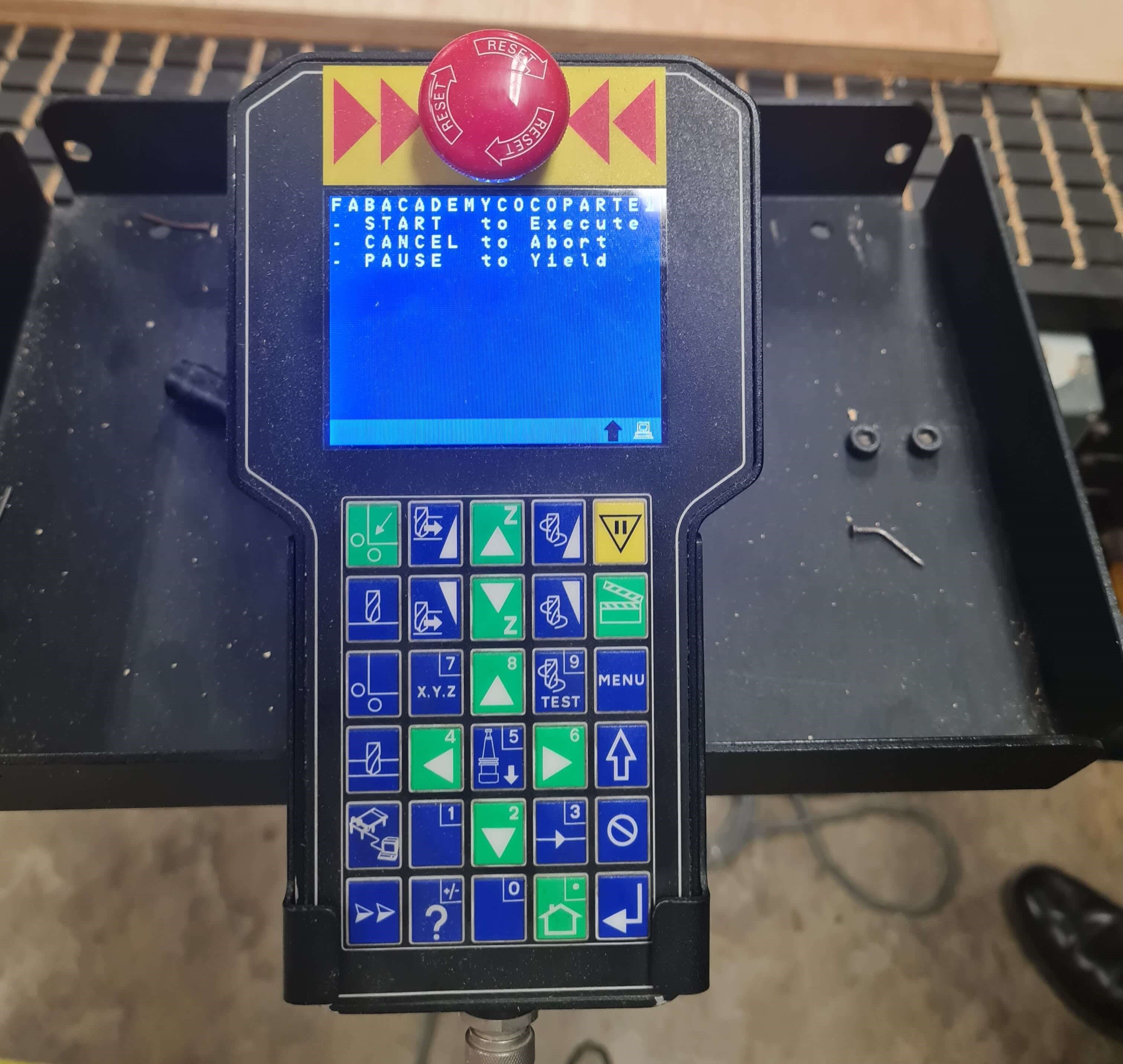
Finally, once the nesting and tool database setup are complete, the software generates the G-code, which is the programming language that instructs the CNC machine on how to cut the parts. The G-code contains precise instructions for the movement of the machine's axes, the speed and direction of the cutting tool, and any other actions that are necessary to produce the desired parts. This G-code is send from a PC via usb serial to the machine. The application is called Job Console , allowing it to execute the cutting process automatically, with minimal manual intervention.
The next step is to export the G-code file generated by the Enroute software into the Multicam Job Console. The Job Console is responsible for loading the file into the machine and monitoring the current state of the G-code execution. This ensures that the milling process is managed efficiently and that any issues can be promptly addressed.
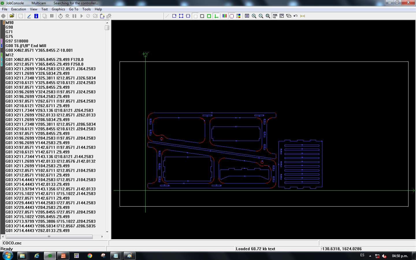
The purpose of this G-code simulation is to verify that EnRoute software correctly prioritizes the routing paths and to review the G-code.
The CNC Router will perform a Z Axis lift and then Home the X-Y Axis. This homing procedure will define the Machine Coordinates for preventing movements out of bounderies. When setting up the Stock Material a Custom Origin will be needed.
For this step, I first needed to send a tool change command to pick up the tool I was going to use. Then, I jogged the toolhead to the X-Y origin position of my stock and set the X-Y origin accordingly.
For the Z-axis stock origin, two Z probing are needed. First, the machine probes the suction platform to ensure the mill does not hit the suction bed, primarily for safety purposes. Next, the top surface of the stock material needs to be probed to set the Z-axis origin.
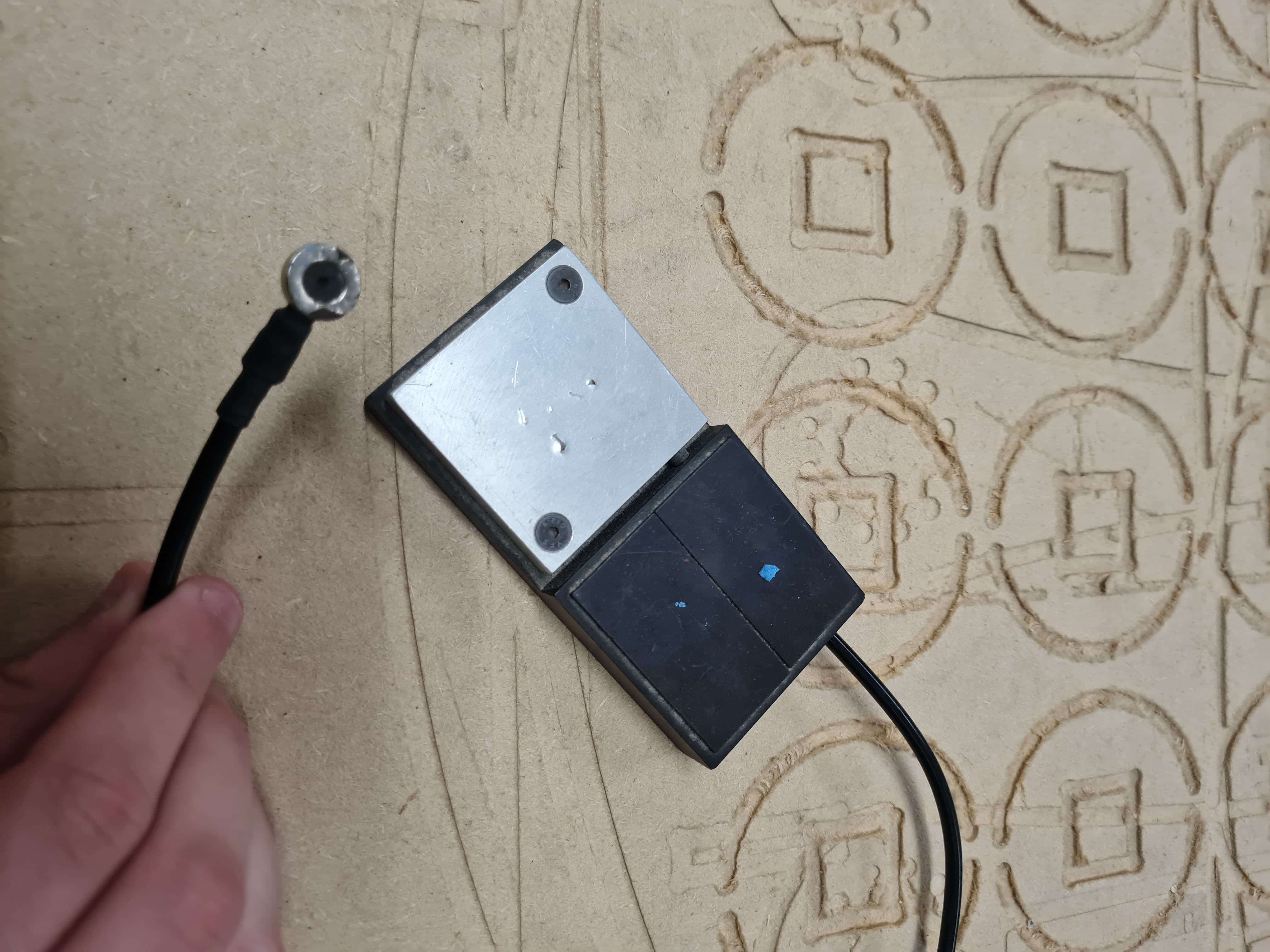
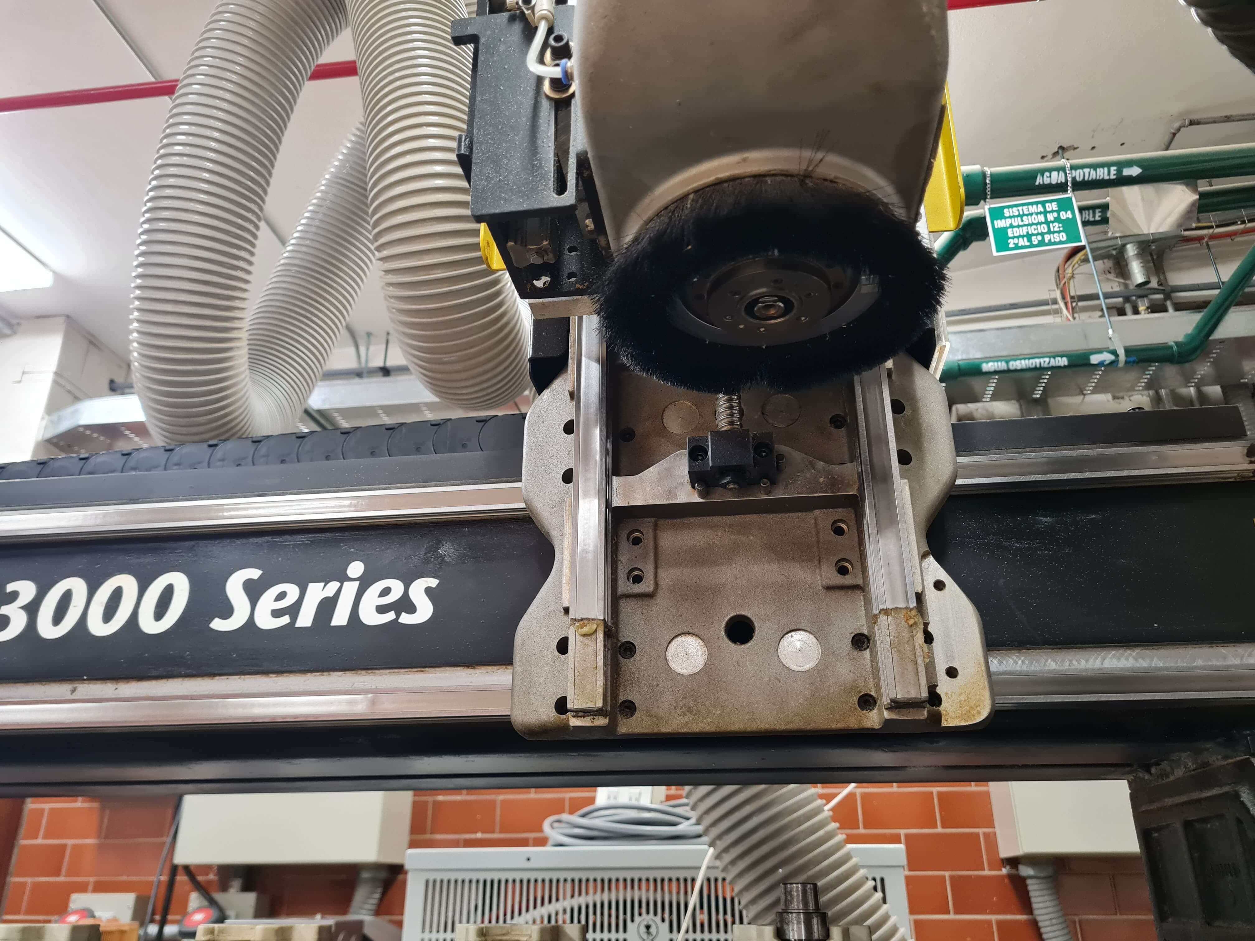
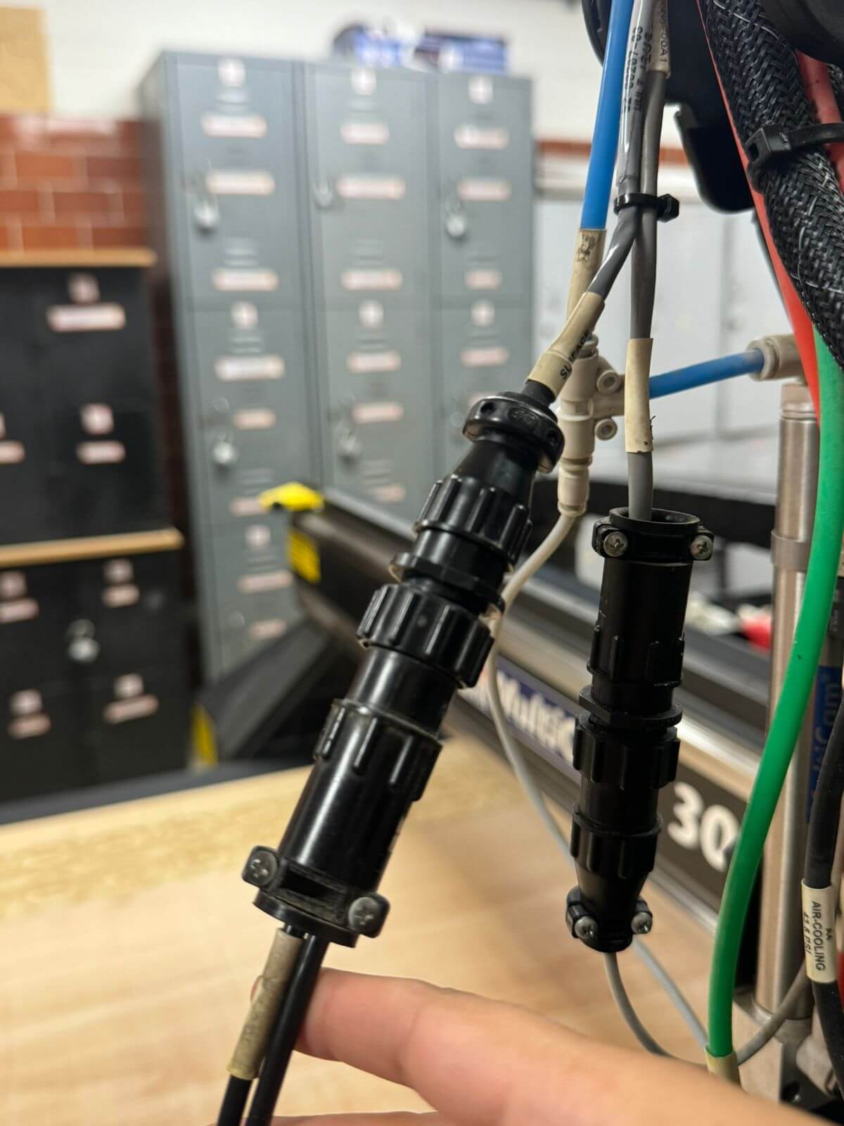
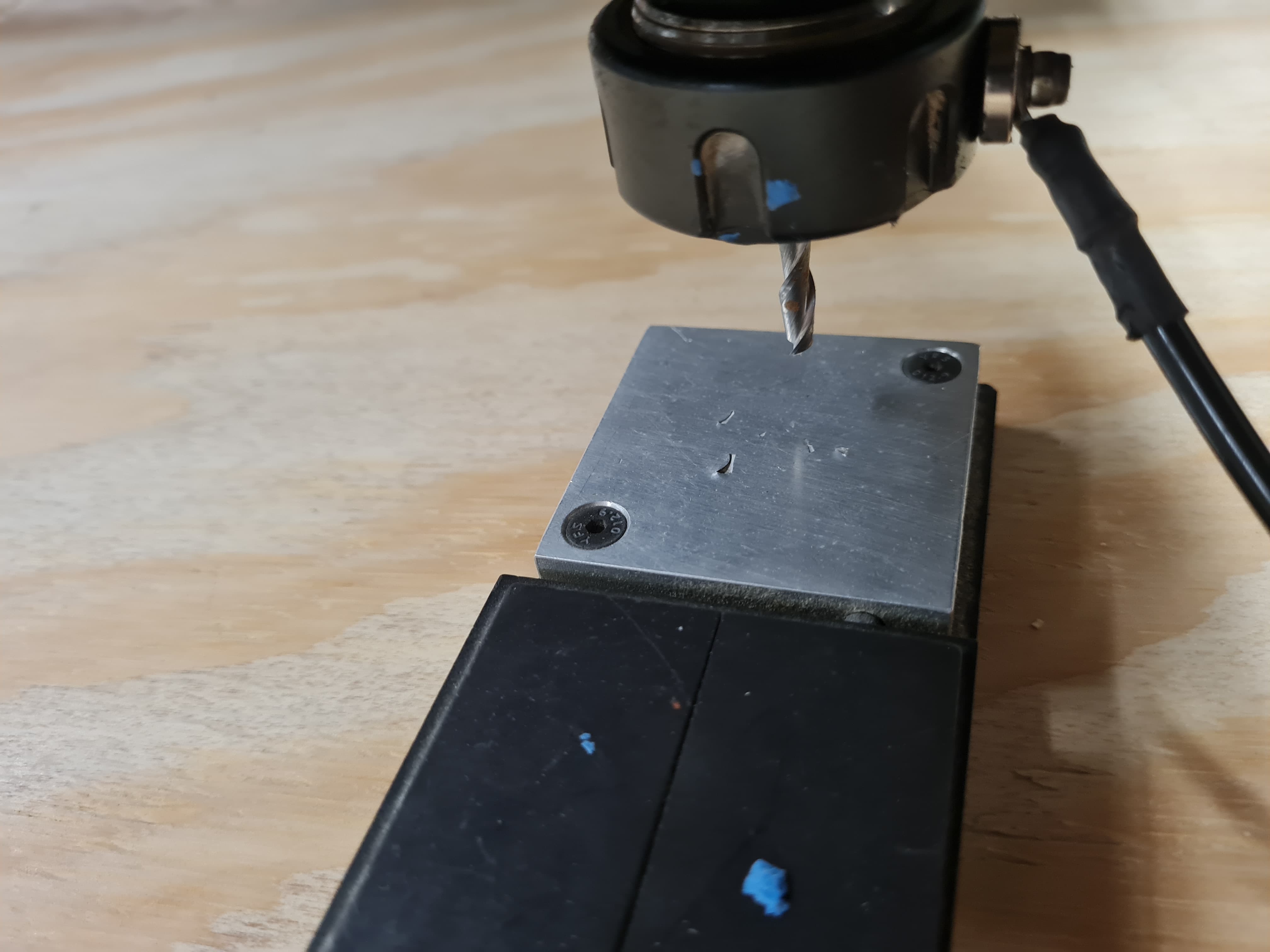
For the probing process, the Z-sense probe is connected via a fast connector that hangs on the toolhead of the router. Then its placed between the sensing surface and the tool. It is crucial to have good continuity between the tool and the Z-sense probe, which is achieved by using a magnetic connection to the tool. This ensures accurate and safe probing of the Z-axis.
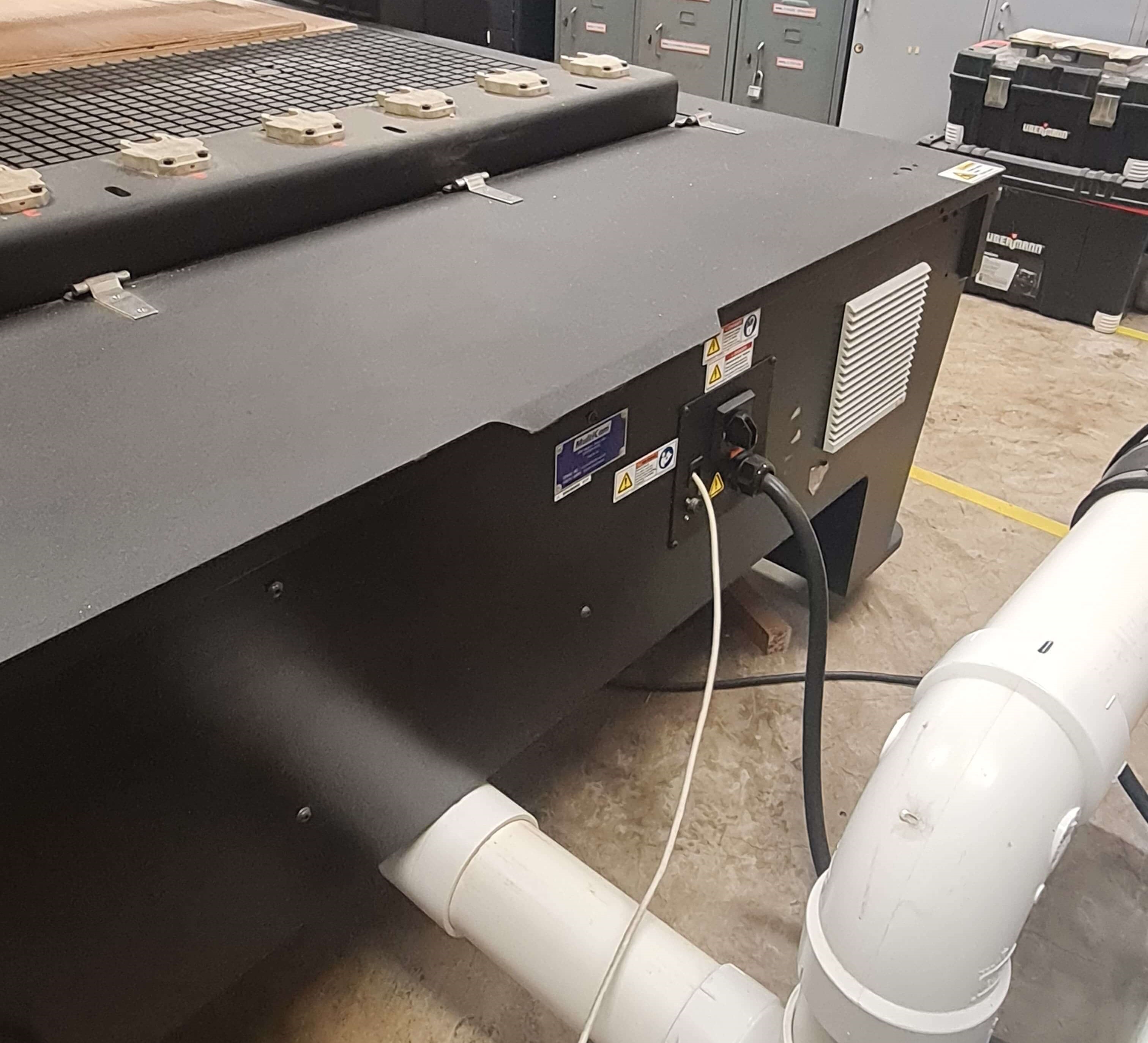
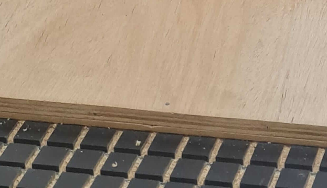
For this step, I secured the stock material to the sacrificial MDF. The machine features a suction system to hold the stock material in place. To prevent damaging the original platform, our Fab Lab decided to use a 6mm sacrificial MDF sheet. The machine suctions the 6mm MDF, and the 18mm plywood is mounted on top, fixed with six nails through both sheets. The thickness of the plywood varies from 17.8mm to 18.4mm. To ensure complete cutting, the G-code is generated to mill the full 18mm thickness plus an extra 1mm into the sacrificial MDF, ensuring the end mill cuts through the entire material without any issues.
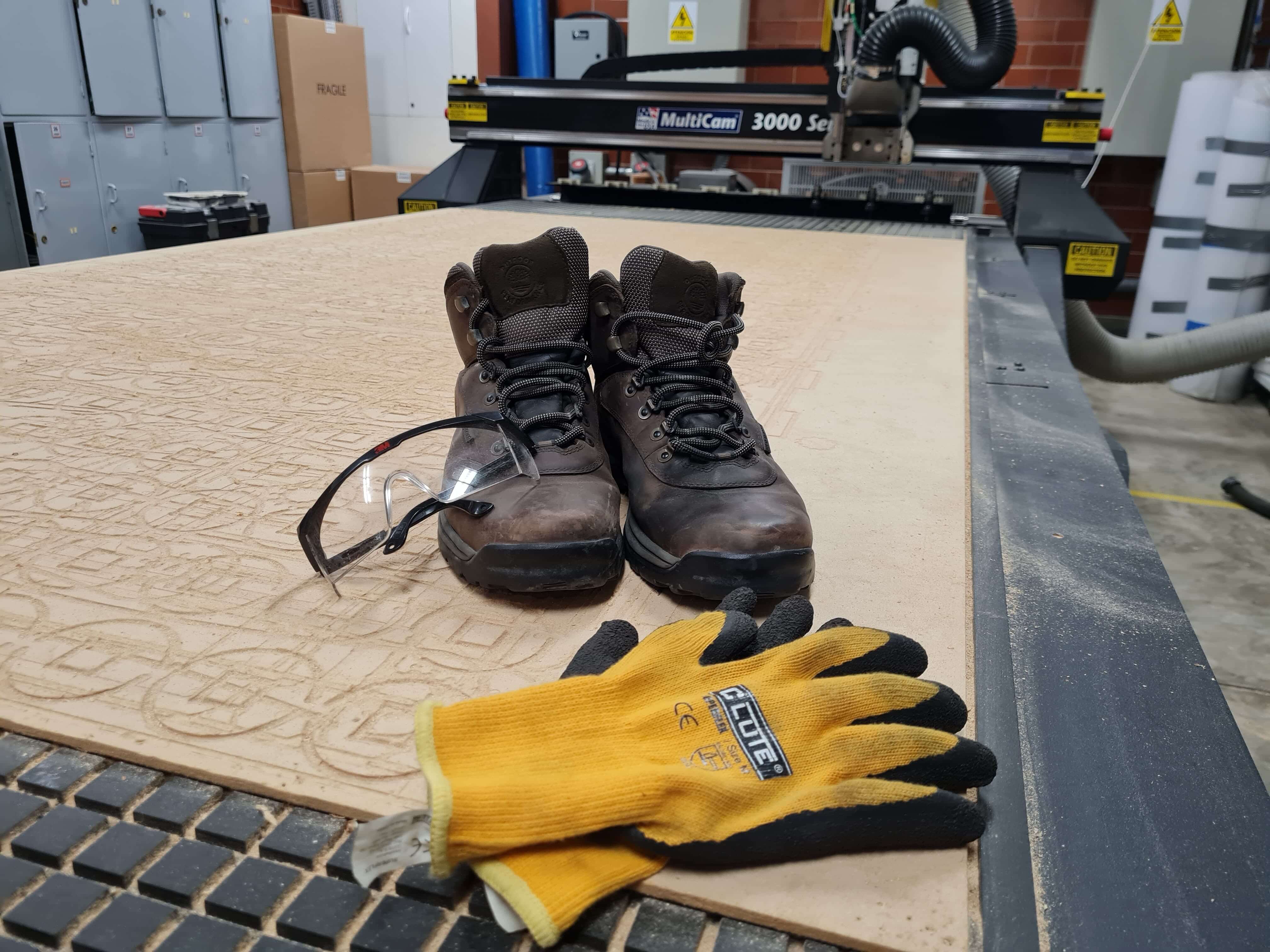
To operate the CNC router responsibly, it is mandatory to have the appropriate personal protective equipment (PPE).
The personal protective equipment (PPE) used for the job is crucial to ensure safety in the workplace. For this particular task, various types of PPE are required to protect the worker from potential injuries. These include steel-toe boots, which provide protection against impact to the feet; protective goggles, shielding the eyes from flying particles and safety gloves, guarding the hands against cuts and abrasions.
For the assembly process, I used a rubber hammer to prevent damaging the wood while inserting all the press-fit connections.


This week's group assignment required me to design and CNC route two types of joints. I chose parametric modeling for ease of use due to its numerous benefits.
Parametric modeling allows for quick adjustments and iterations, ensuring precise and functional designs while saving time. Using Inventor Professional, I focused on T-bone and dogbone joints. I defined parameters such as fit tolerance, pin width, and material thickness. By adjusting these parameters, I could easily test different variations and optimize the designs for strength and assembly efficiency.
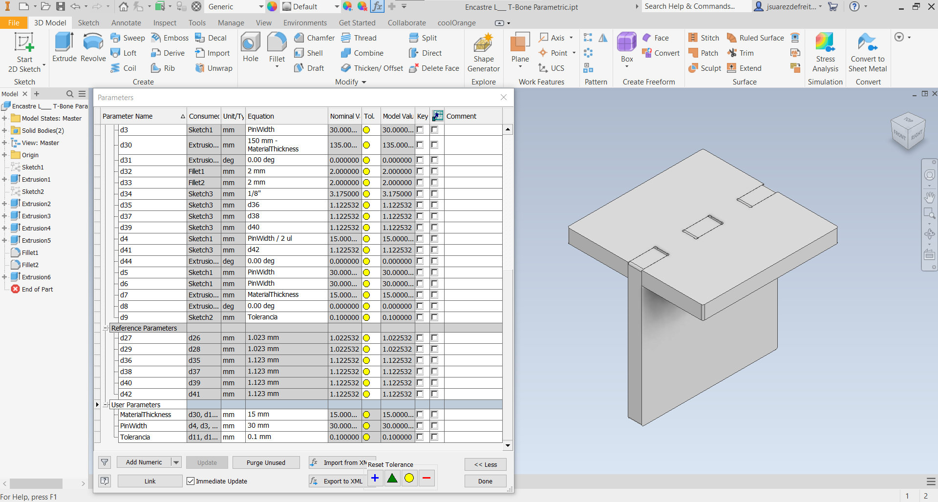
I learned how different tolerance fits can be useful in the fabrication of press-fit reliable connections and how to effectively use the CNC router to reduce post-machining sanding. This knowledge further enhanced the precision and quality of the joints.