
Week 4: Electronics Production
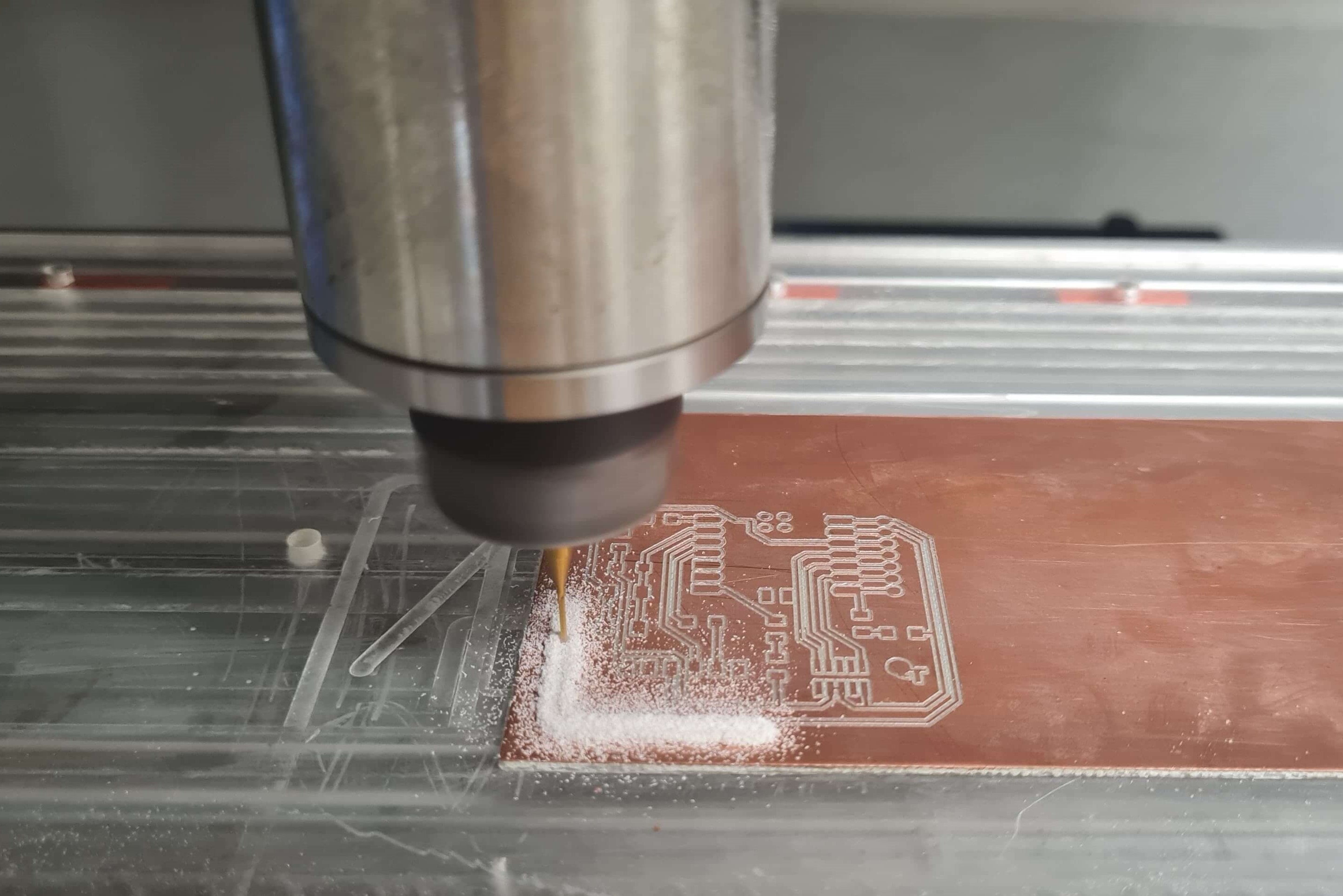
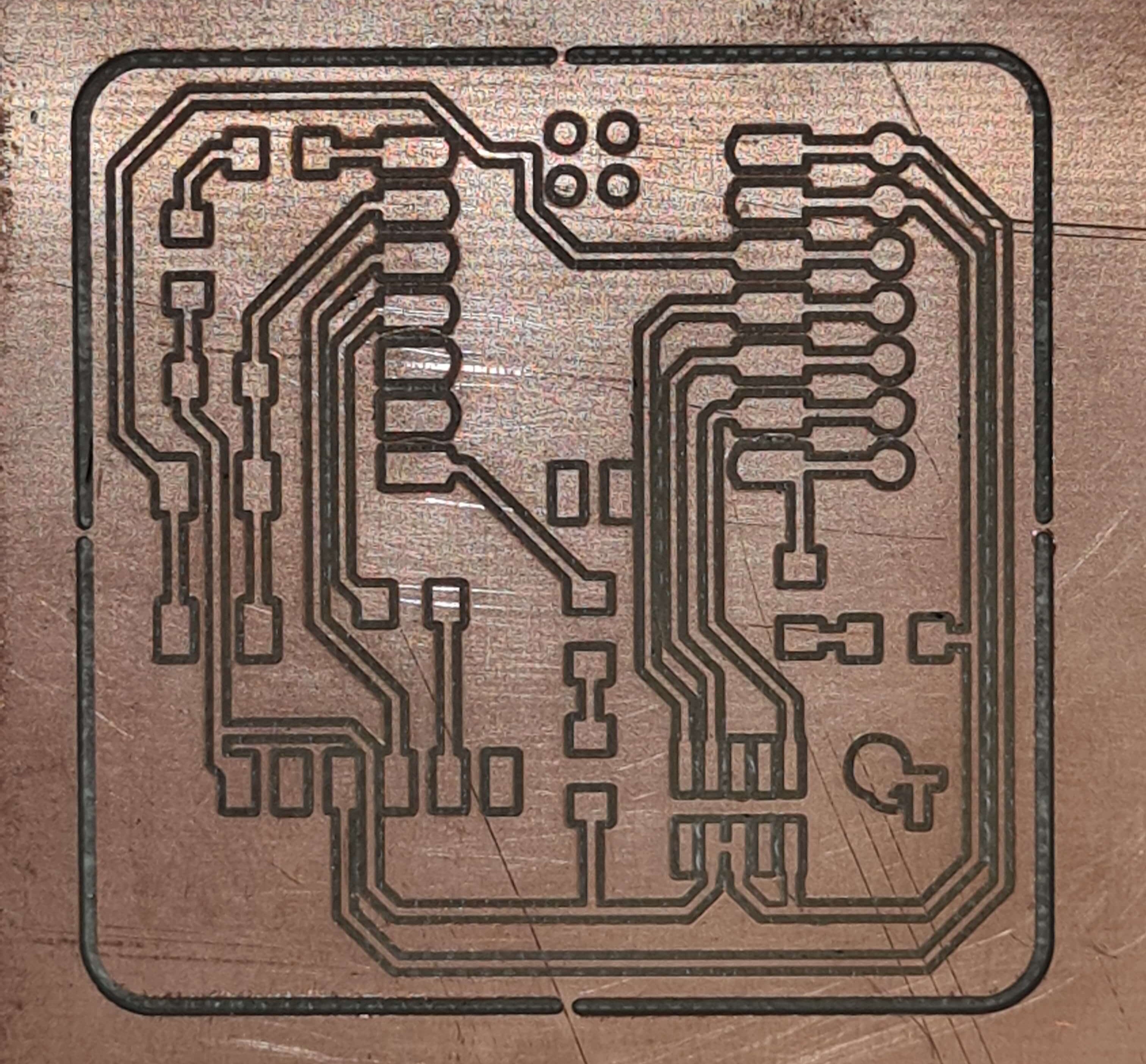
This week, I learned how to manufacture a PCB prototype board using a CNC mill and SMD components. This hands-on experience gave me valuable insights into PCB fabrication and SMD components handling. Utilizing a CNC mill enables precision and accuracy in carving out intricate and delicate circuit designs. Meanwhile, integrating SMD components offers a compact and efficient solution for circuitry in tight spaces.
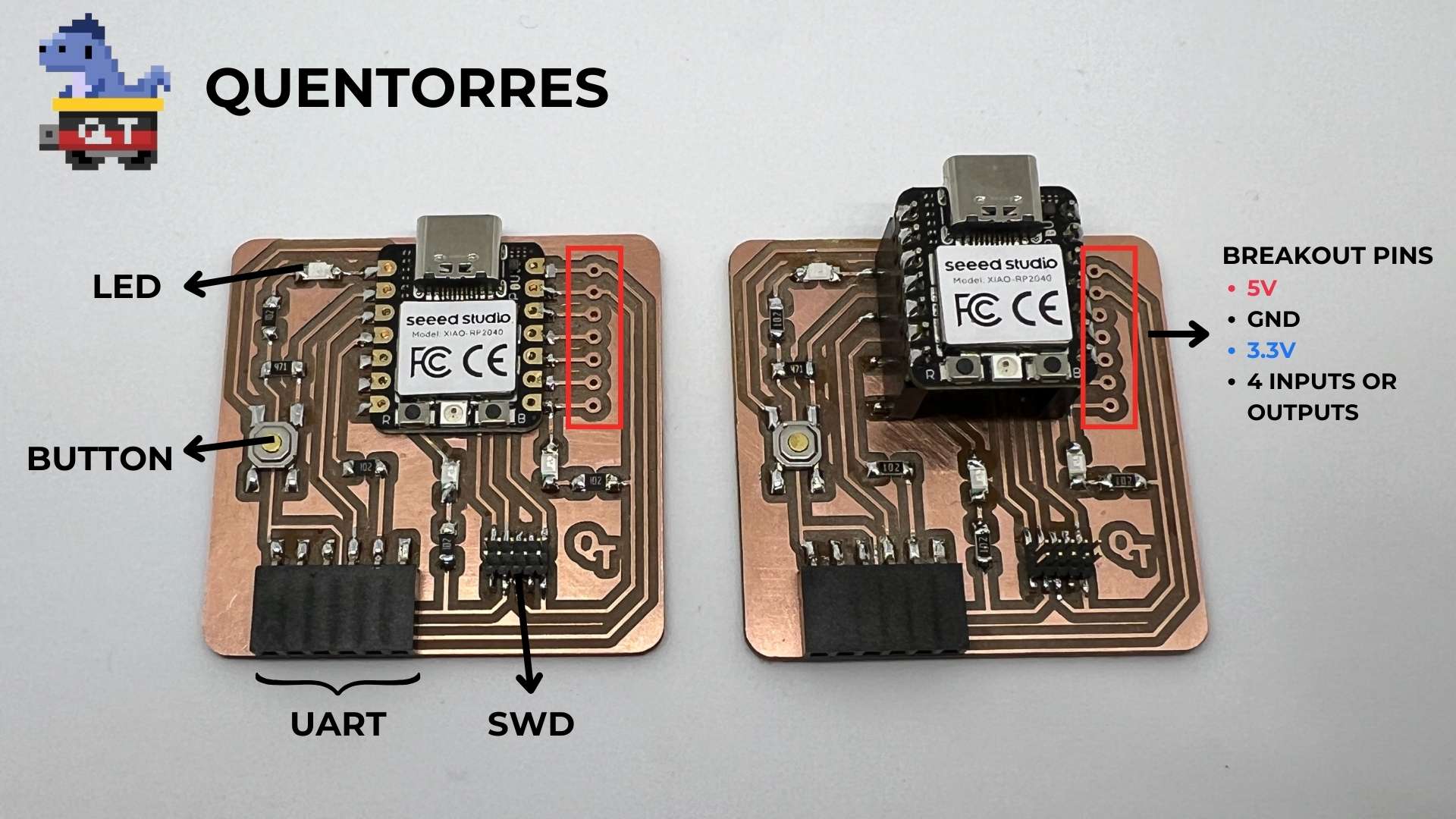
The PCB board for this assignment is the Quentorres SWD+UART Adapter+Hello Board initially created by Quentin Bolsée and later redesigned by Adrián Torres from FAB LAB León
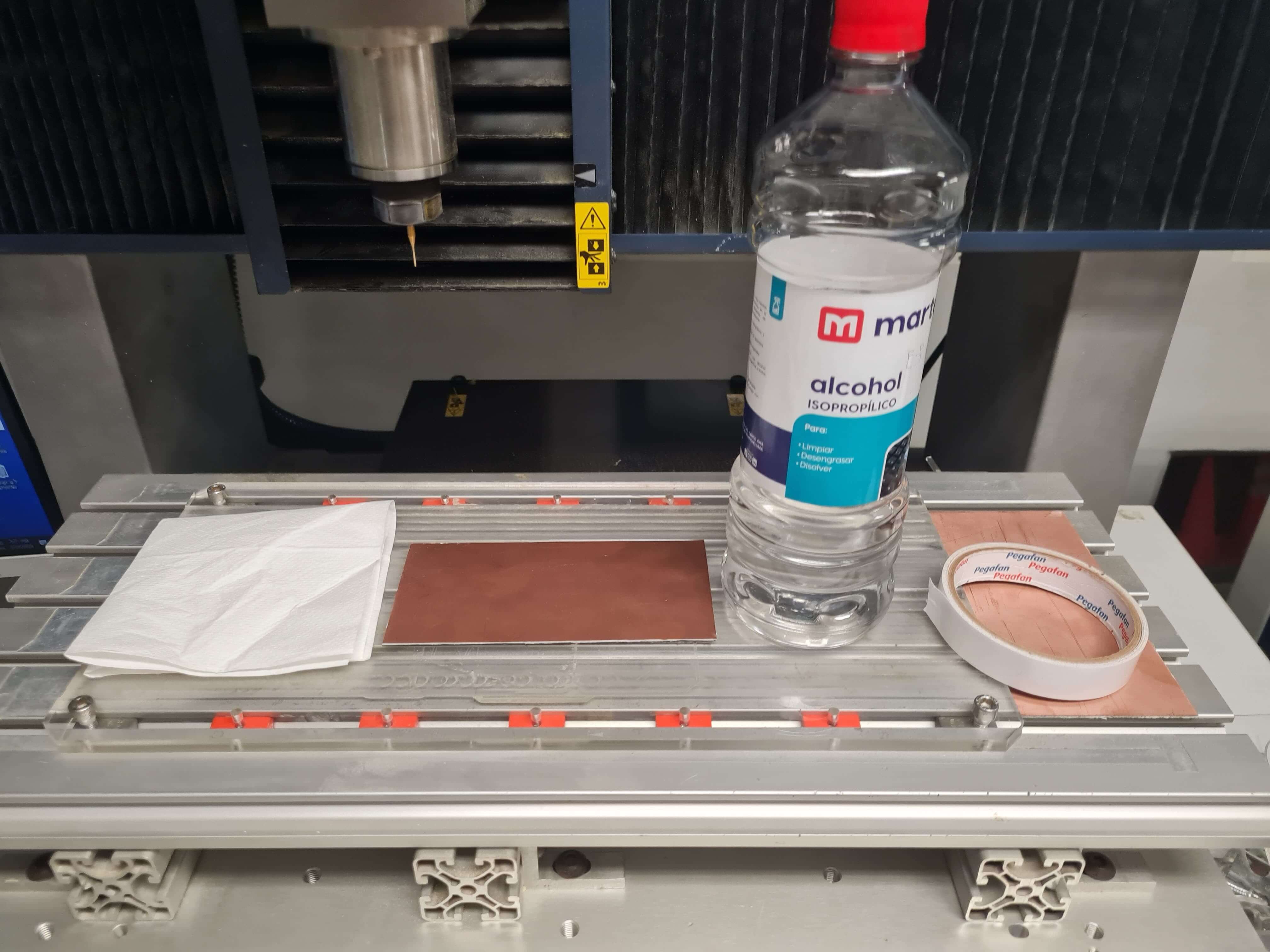
Prepare the Work Surface: Clean the surface of the CNC mill bed and PCB to ensure there is no debris or residue that could affect the adhesion of the tape. For this step I used Isopropyl alcohol and paper towel.
Apply Double-Sided Tape: Carefully apply the double-sided tape to the PCB, ensuring thorough coverage. It's crucial to apply the tape evenly across the surface without any overlaps. Removing overlaps helps maintain the flatness of the PCB and prevents potential misalignment during the milling operation. Then, remove the protective plastic backing from the tape. Align the PCB as straight as possible on the CNC milling bed, ensuring it is positioned accurately according to the NC. Apply even pressure across the entire surface of the PCB to ensure optimal adhesion to the tape. This ensures stability and precision throughout the milling process.
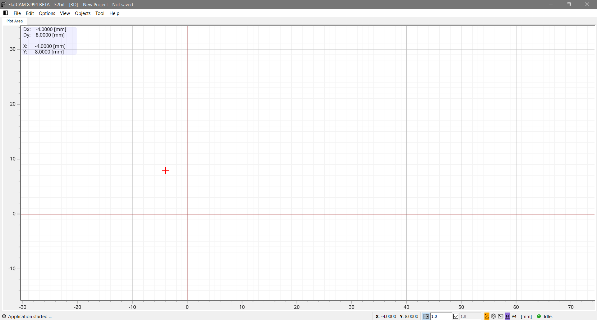
Setting Custom Origin (XY): Define a custom origin point using the CNC mill's software. This allows you to precisely position the milling tool at the starting point of your PCB design. The quadrant established in the CAM program must coincide with the origin set in the CNC mill software. This ensures seamless communication between the CAM program and the CNC mill, allowing for accurate translation of design coordinates into machine movements. In a few words, ensure that the custom origin aligns with the origin point specified in your NC file to mill in the right place.
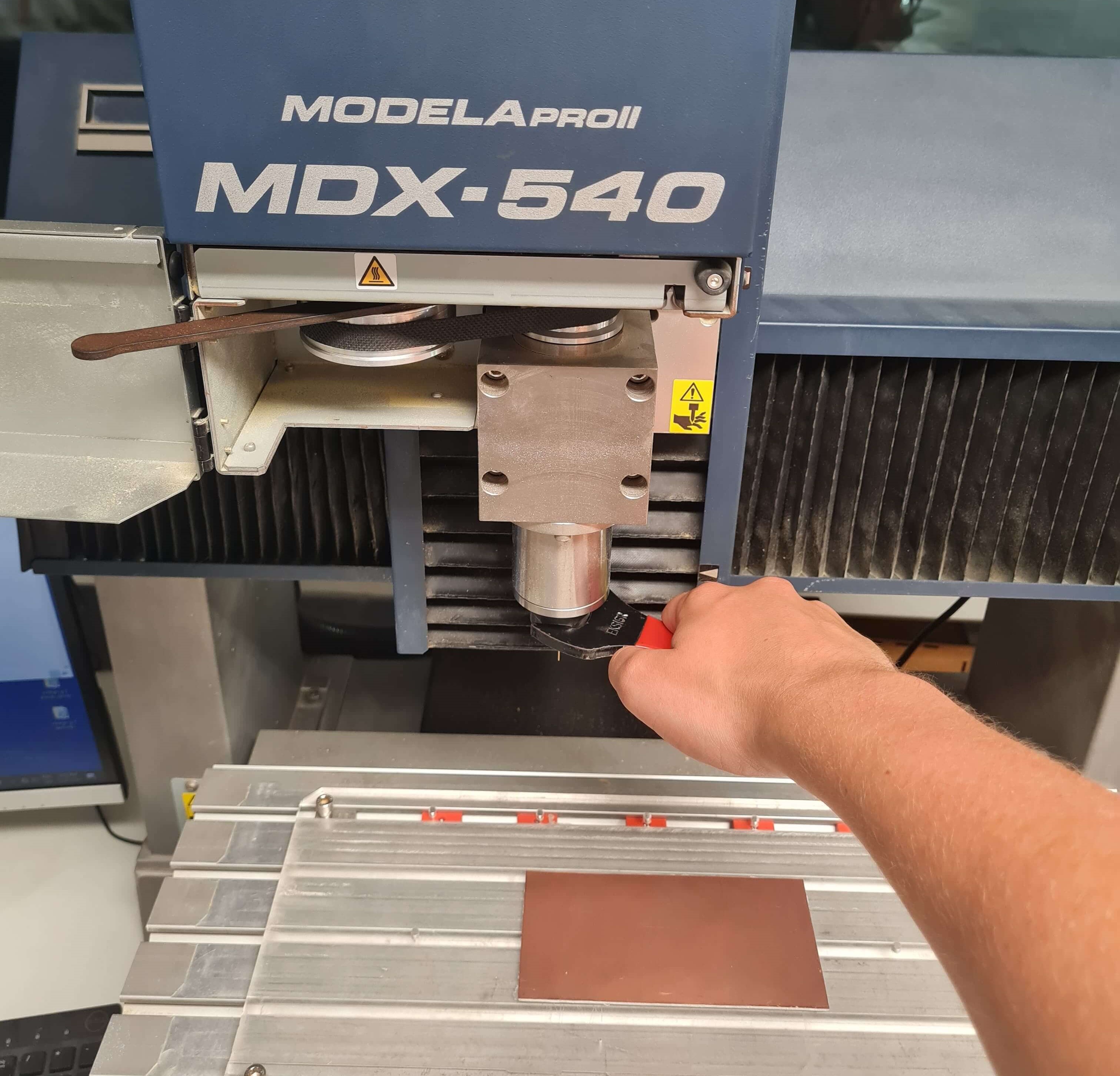
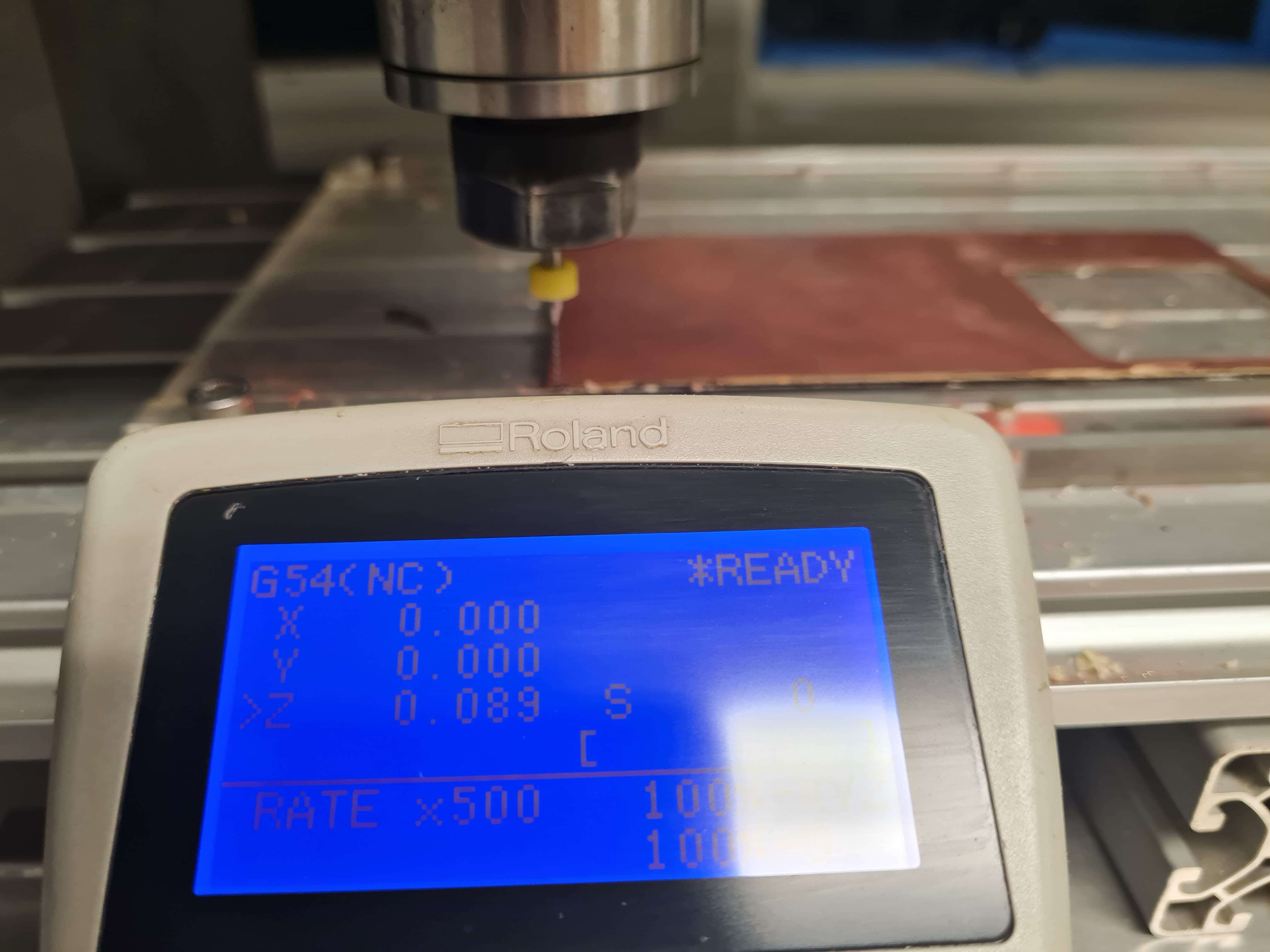
Z0-SENSE (Z): During this process, the CNC machine lowers the tool until it contacts the Z probe. Upon contact, the tool triggers a signal indicating the Z0 position. Subsequently, the Z axis travels to its maximum position. My recommendation is to manually verify the Z-axis height after the Z0-SENSE process. I've encountered issues where the probe fails to trigger due to a split-second interruption, often resulting in a minor hole on the brass probe. To mitigate this, it's crucial to ensure a flawless connection between the machine and the Z probe. This manual verification step adds an extra layer of assurance, guaranteeing precise Z-axis referencing and minimizing the risk of inaccuracies during machining operations.
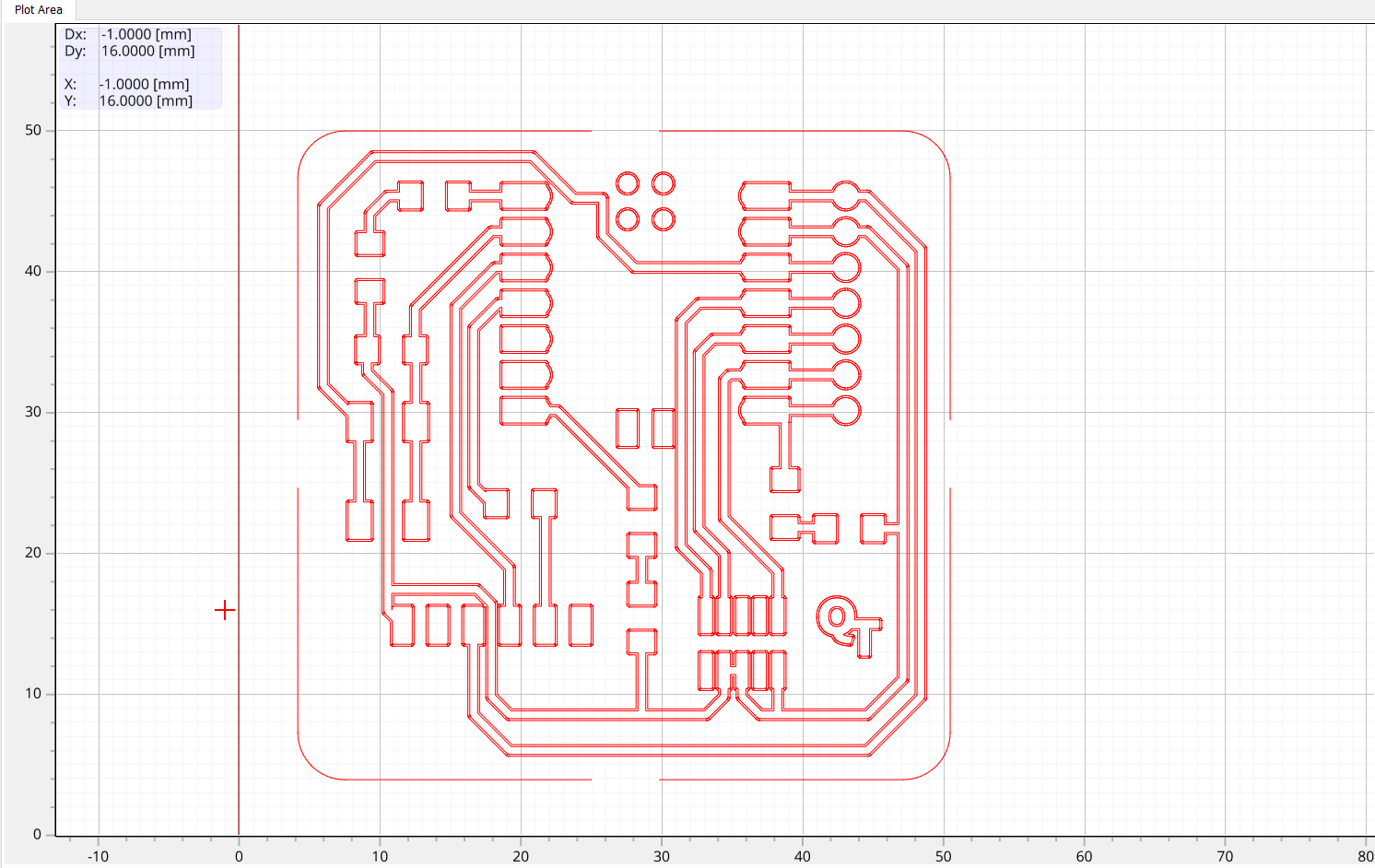
I chose using FlatCAM for CNC milling and isolation tasks due to its open-source nature, versatile file format support (Gerber), intuitive interface, and active community. FlatCAM's ability to generate G-code, coupled with its customization options and Tool Database, makes it a reliable choice for achieving accurate and efficient machining results.
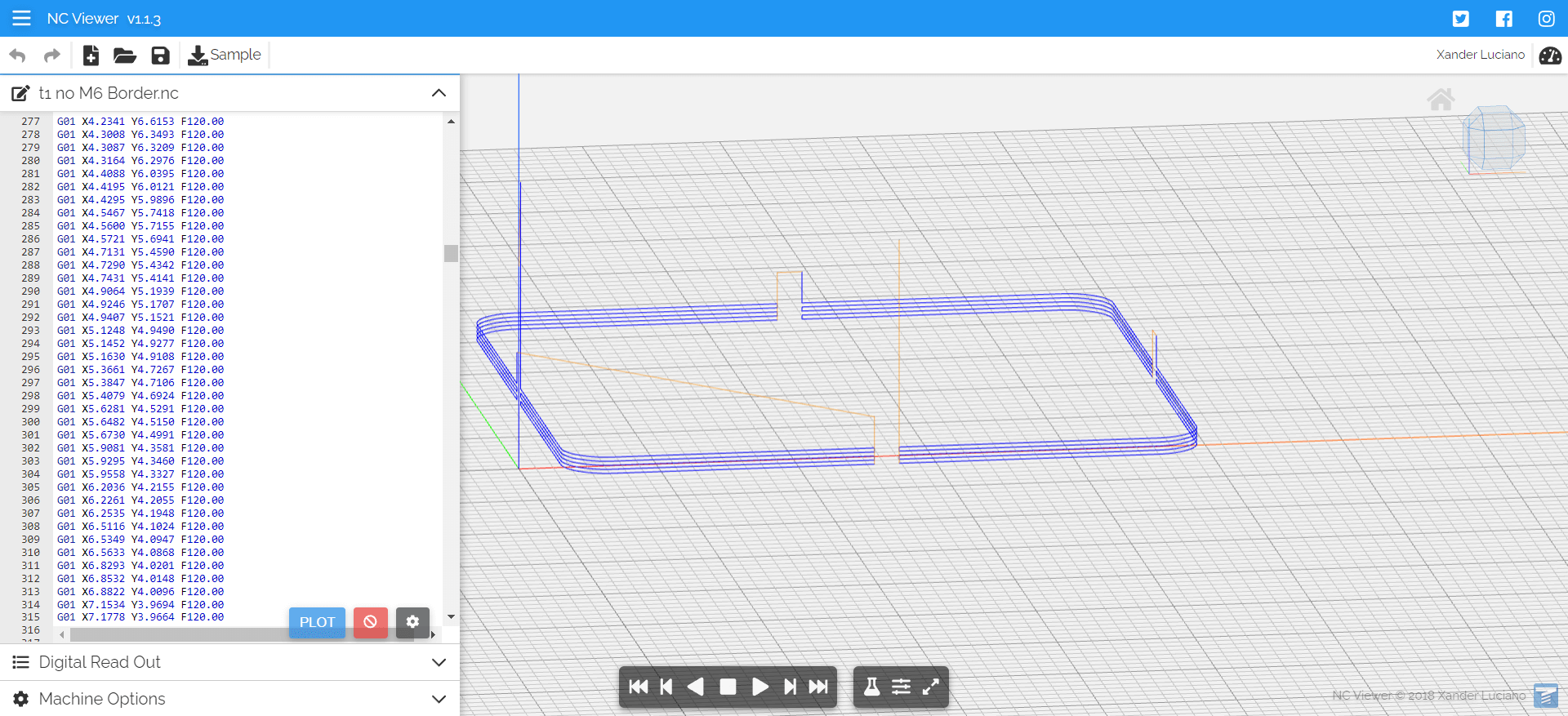
FLATCAM features an in-built G-code viewer for the G-code it generates. However, due to limitations within FlatCAM, I opted to use an online G-code viewer, specifically the NC Viewer, were I could see the z-axis movements.
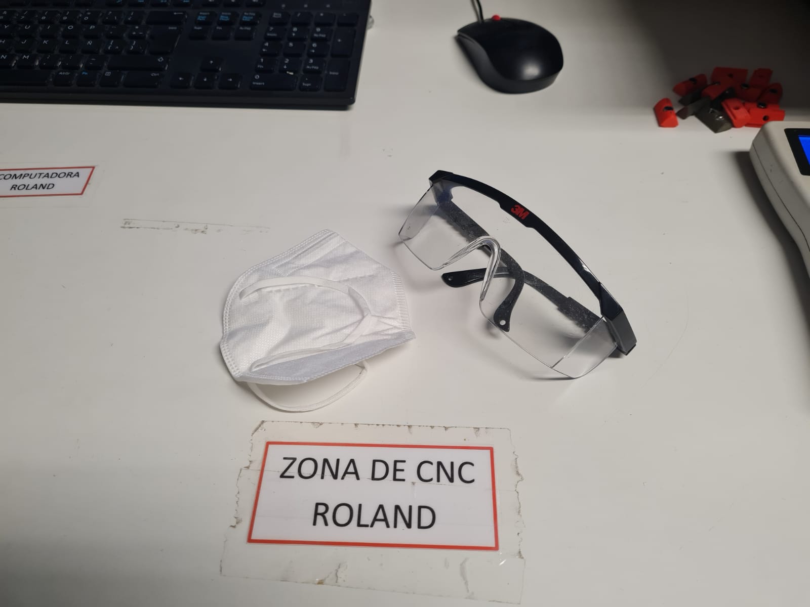
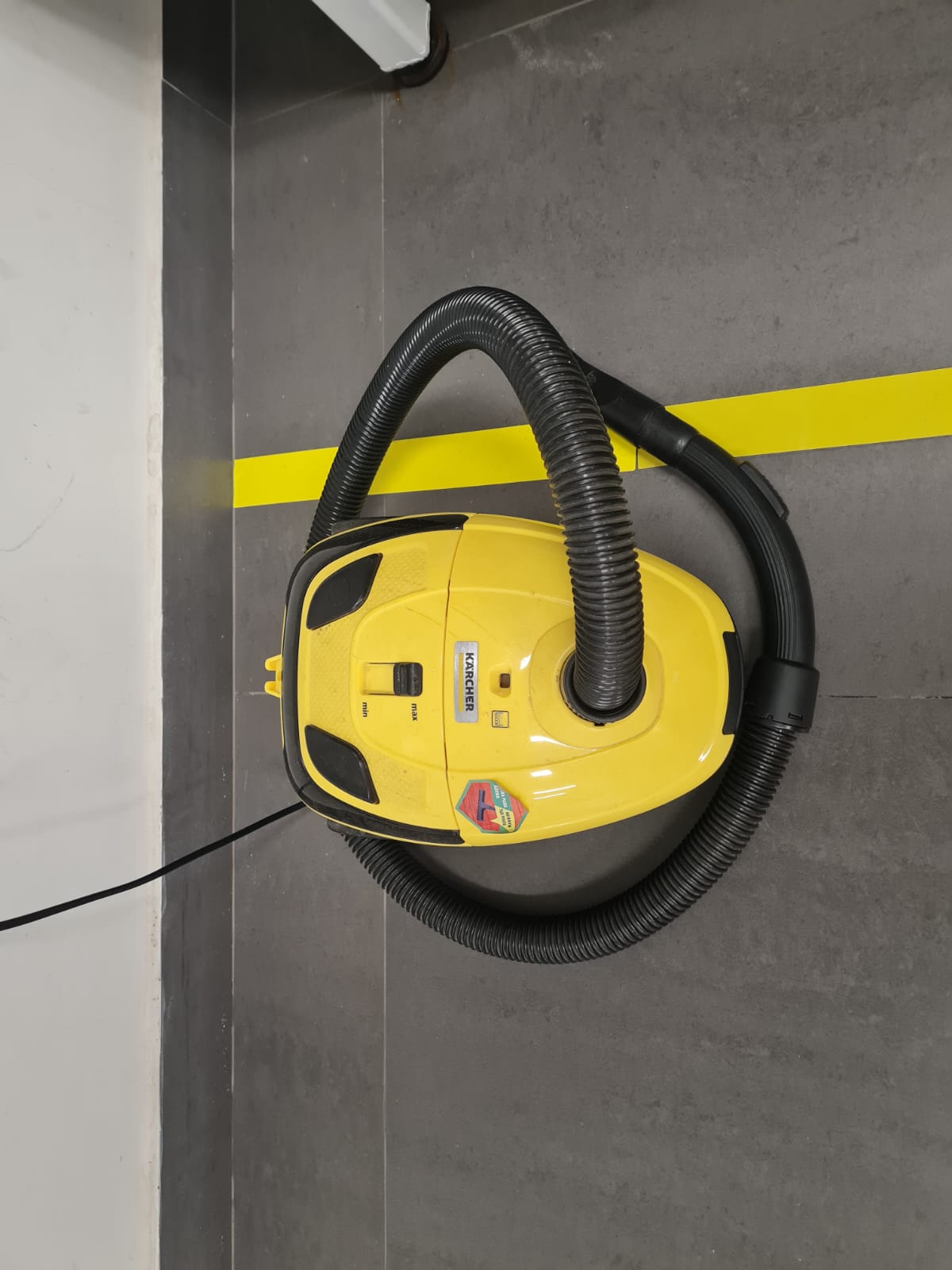
When milling printed circuit boards (PCBs), using FR4, a composite material made from woven fiberglass cloth with an epoxy resin binder, poses significant health risks. Machining FR4 generates fine fiberglass particles, which can irritate the respiratory tract, cause coughing, sneezing, and lead to long-term respiratory conditions like bronchitis or fibrosis. The epoxy resin in FR4 can also release toxic fumes, especially if overheated, contributing to respiratory issues. To mitigate these risks, I used a KN95 mask to filter out fine particles, protective eyewear to shield my eyes, and ensured proper ventilation to minimize harmful fumes. I also used a vacuum cleaner to effectively remove fine powder after machining, further reducing exposure.
In my FabLab, we didn't have FR1 PCB material; instead, we had ceramic, fiberglass (FR4), and an old phenolic PCB (Bakelite) with no specification. I wanted to experiment with these three materials, but initially, I decided to use FR4 because it was the most available in the lab, and I needed to perform a lot of testing in my first tries.

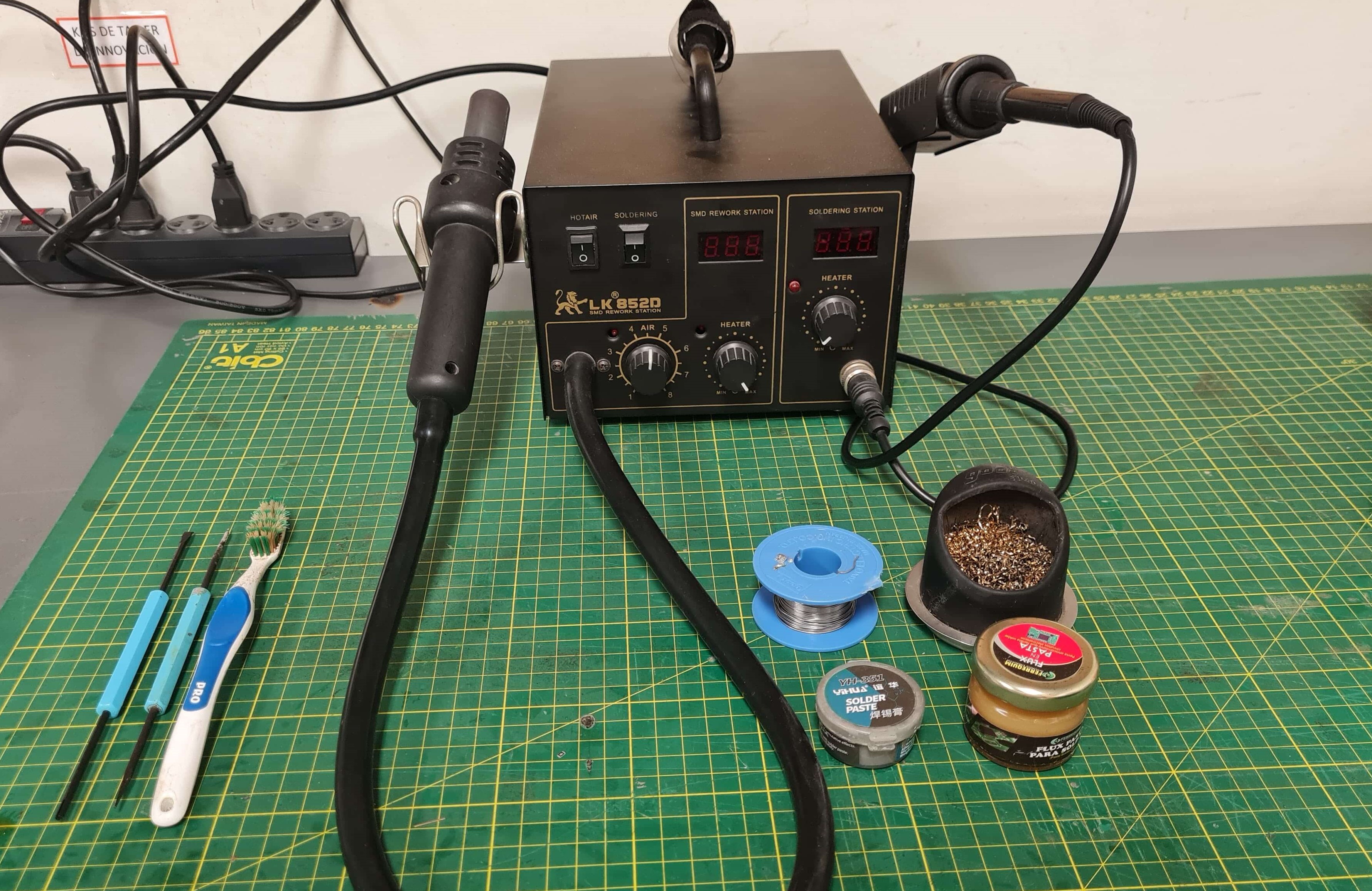
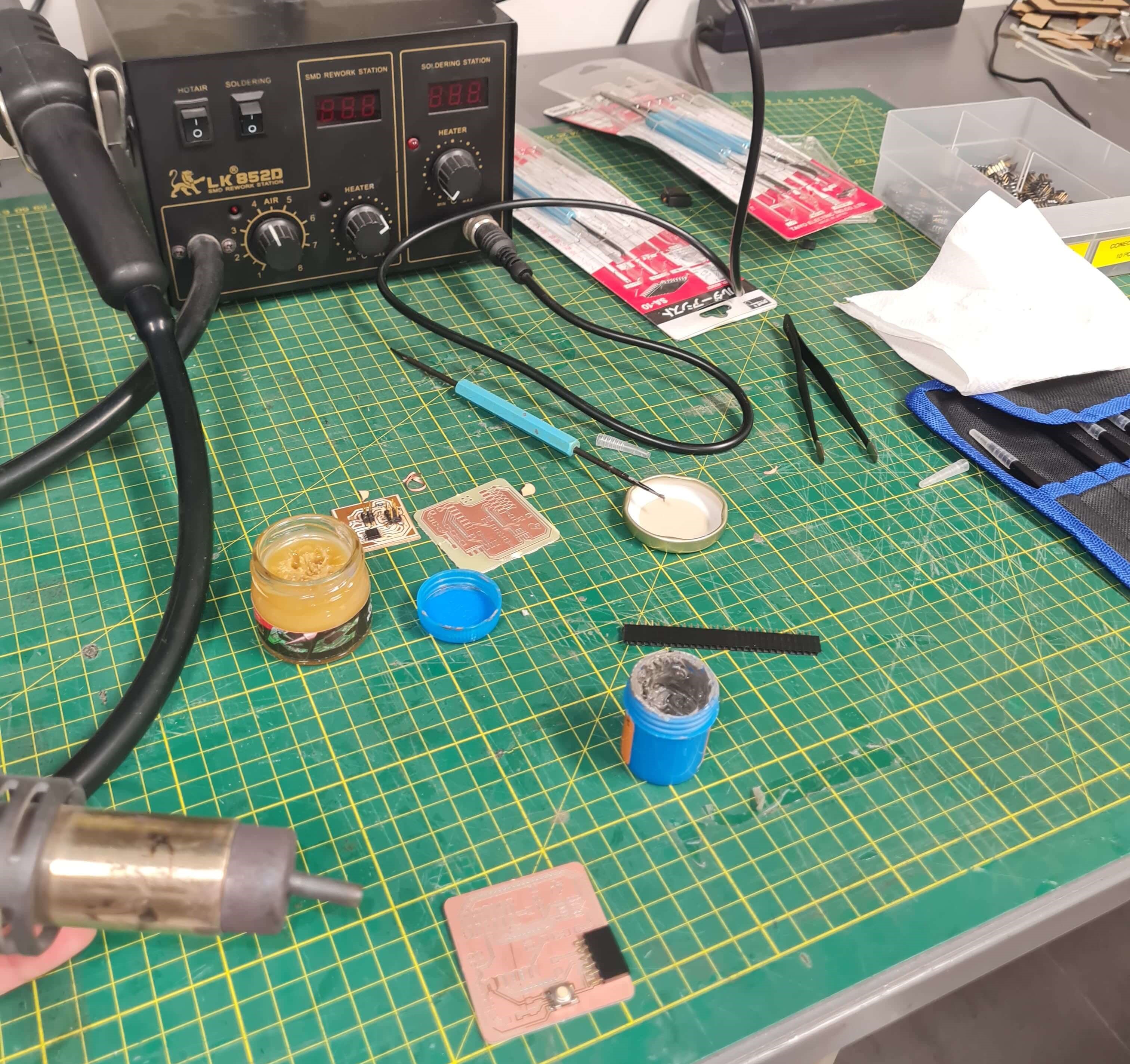
During the soldering process using SMD solder paste and an SMD soldering station, I encountered several challenges. Initially, reliably depositing solder paste onto each pad proved difficult. Once applied, positioning components without them shifting was another hurdle. Drawing from my experience with soldering PCBs using a soldering iron and my keen eyesight and precision, I opted to solder the components manually. Using the "3-second trick" ensured excellent solder joints—shiny and reliable. It's crucial not to overheat the solder, as this can compromise the connection, resulting in a dull, unreliable joint. Achieving a shiny solder joint indicates a well-executed soldering process, ensuring optimal electrical and mechanical performance.
To enhance efficiency, I used tweezers to precisely place each component and secured them in place by soldering one of the connections first. This approach allowed me to focus on soldering without the distraction of shifting components. Additionally, I applied ample flux to prevent overheating of the components and ensure smooth solder flow.
The soldering iron tip was set to a working temperature of 300°C, adjusted between 250°C and 350°C depending on the component's size and pad size. Lower temperatures were preferred for tiny components to avoid damage, while higher temperatures were ideal for larger components and pads to prevent solder from sticking due to sudden temperature drops.
These techniques and considerations ensured reliable solder joints and effective assembly of the PCB, meeting both electrical and mechanical requirements for a successful build.
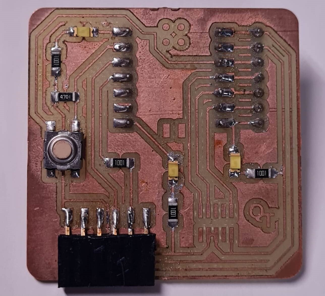
Here, I'm testing a simple code that blinks all three LEDs when the button is pressed.
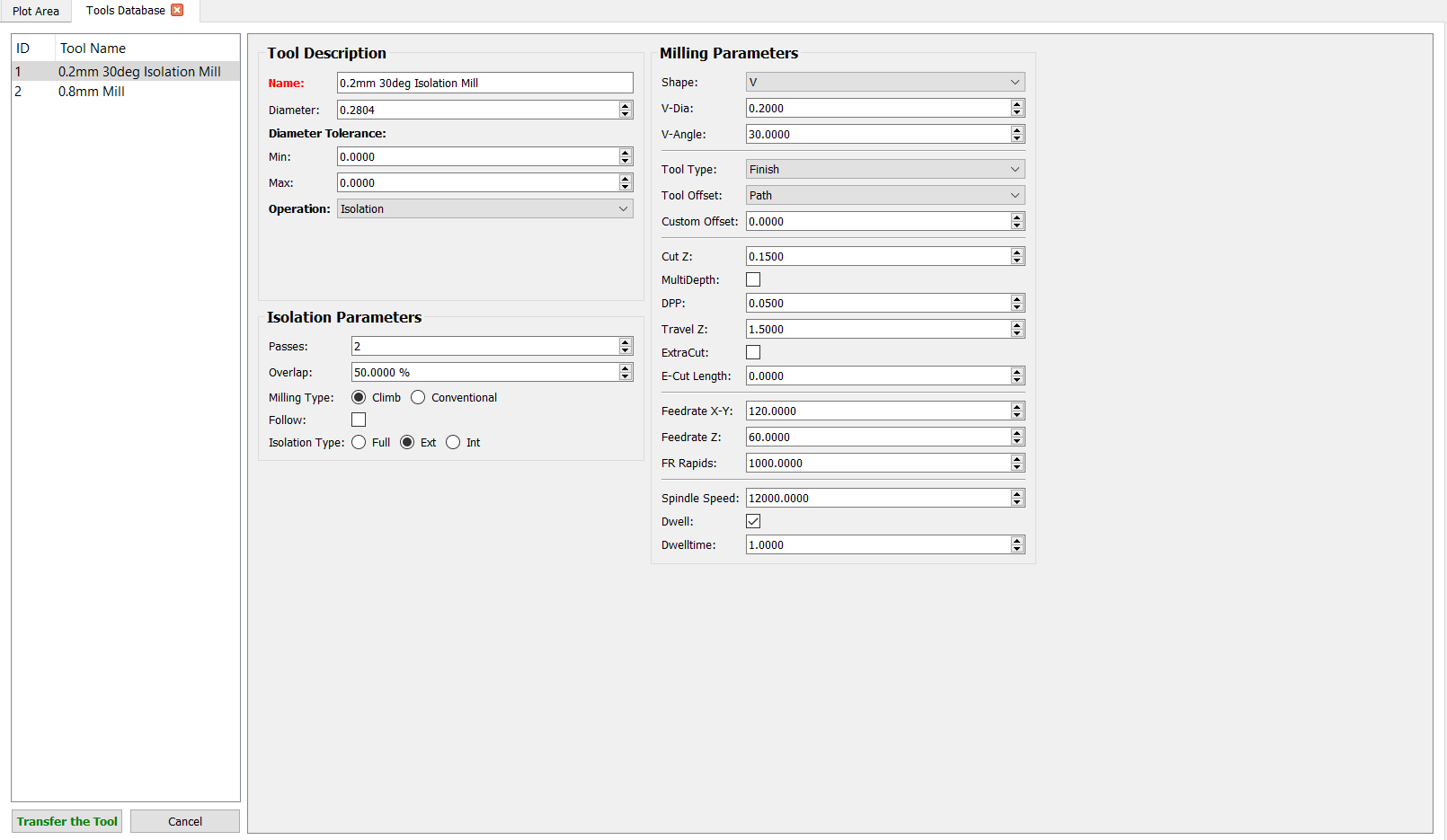
For our group assignment on electronics production, I made significant contributions by experimenting extensively with the tool database in FlatCAM software to create a finely tuned tooling database. This hands-on experience allowed me to optimize the machine's speeds and feeds, leading to a more efficient and smoother workflow when machining PCB boards.
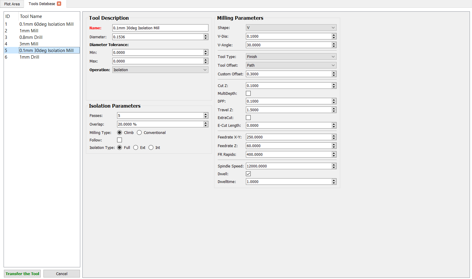
Although the parameters I experimented with were specific to my own trials, we made a collective decision as a group to determine the optimal parameters that would work best for our overall project. This collaborative approach ensured that we used the most effective settings for our shared goals.
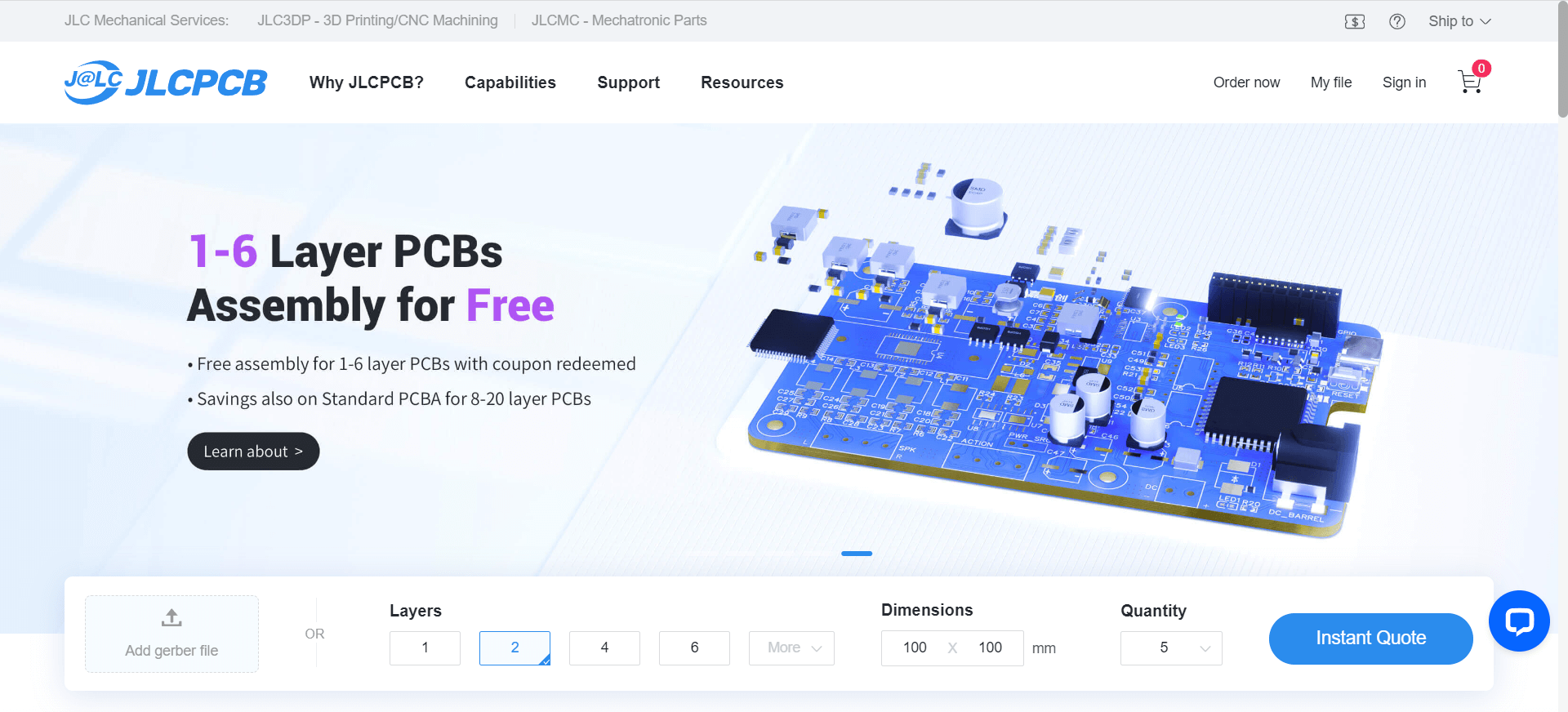
Additionally, I documented the workflow for sending a PCB to a board house. I used JLCPCB for this process, but there are other manufacturers such as PCBWAY among others. This documentation included:
By creating this well-tuned database, we were able to save a significant amount of time when generating G-code. This streamlined the process, making it much more straightforward and efficient for our team to produce high-quality PCB boards.