Week 12: Input Devices
This week's assignment involves utilizing an input device on a self-designed board. My primary objective is to develop the electronics for my final project. The chosen board needs to sense a 75-gram paper. Therefore, I decided to design a board featuring an infrared (IR) LED, equipped with a precision potentiometer for adjusting the LED's brightness. This setup allows me to calibrate the sensor's sensitivity as needed, ensuring accurate detection of the paper.
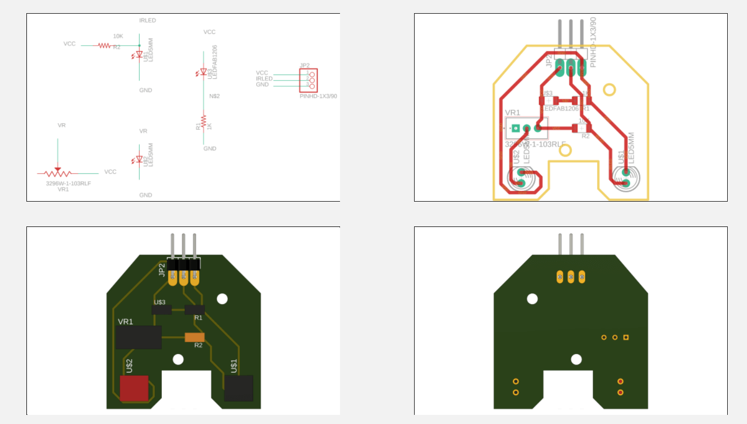

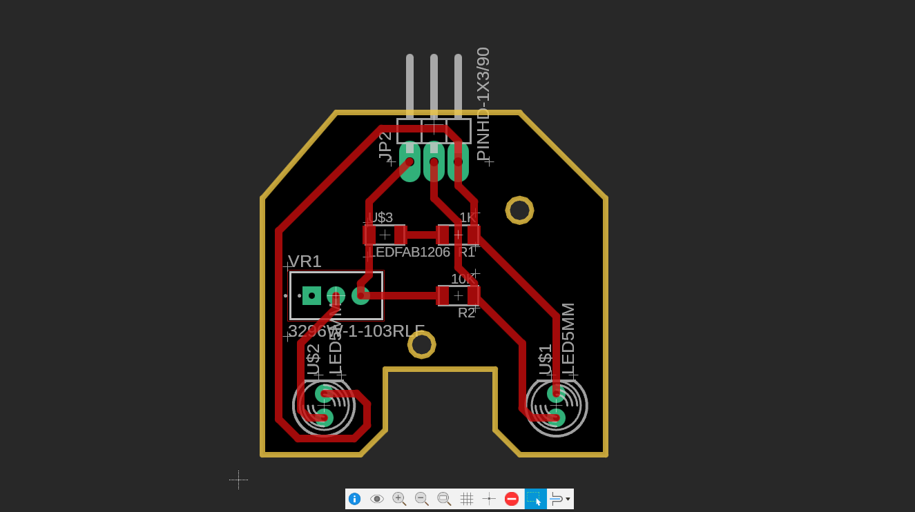
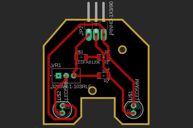
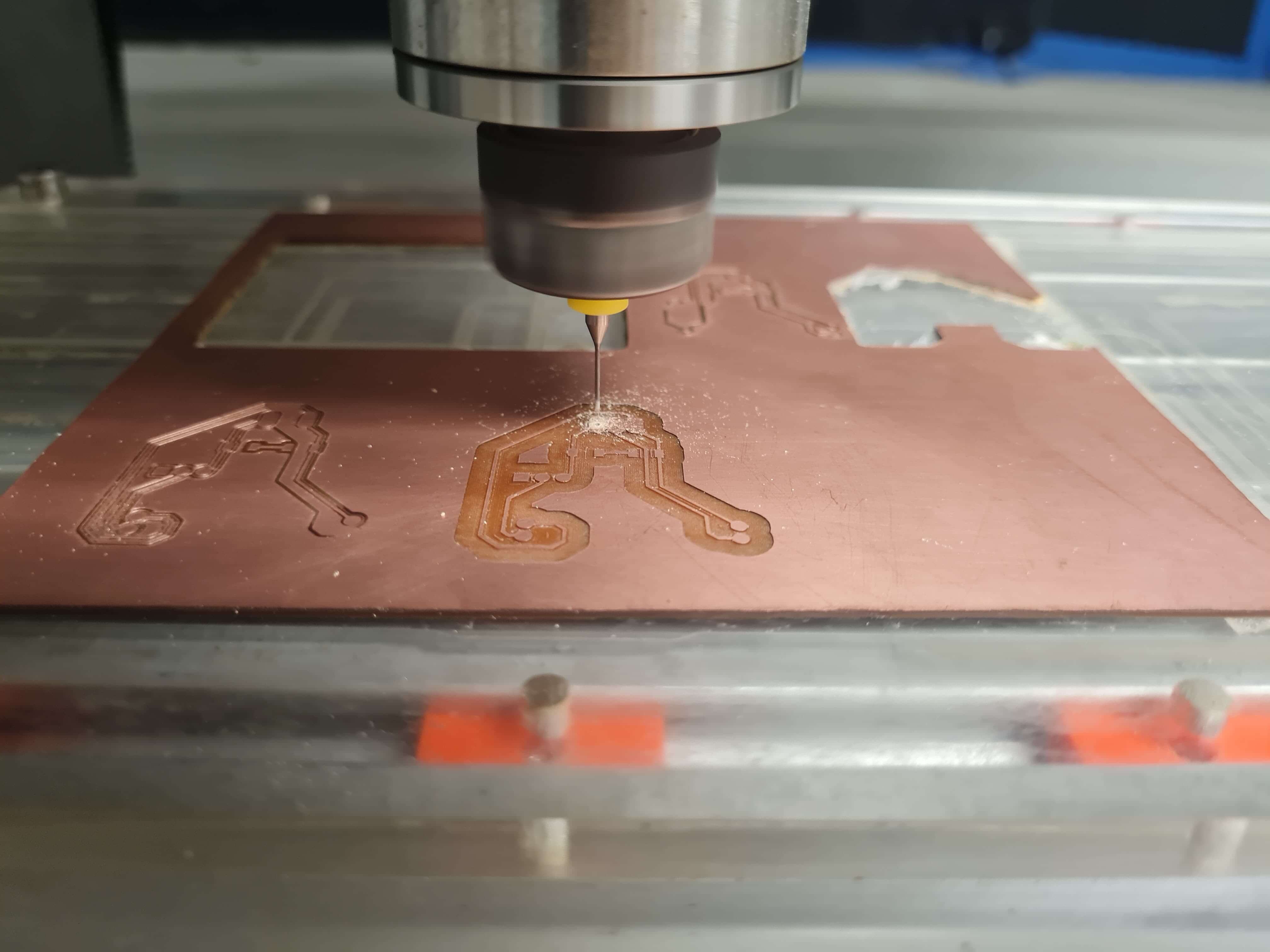
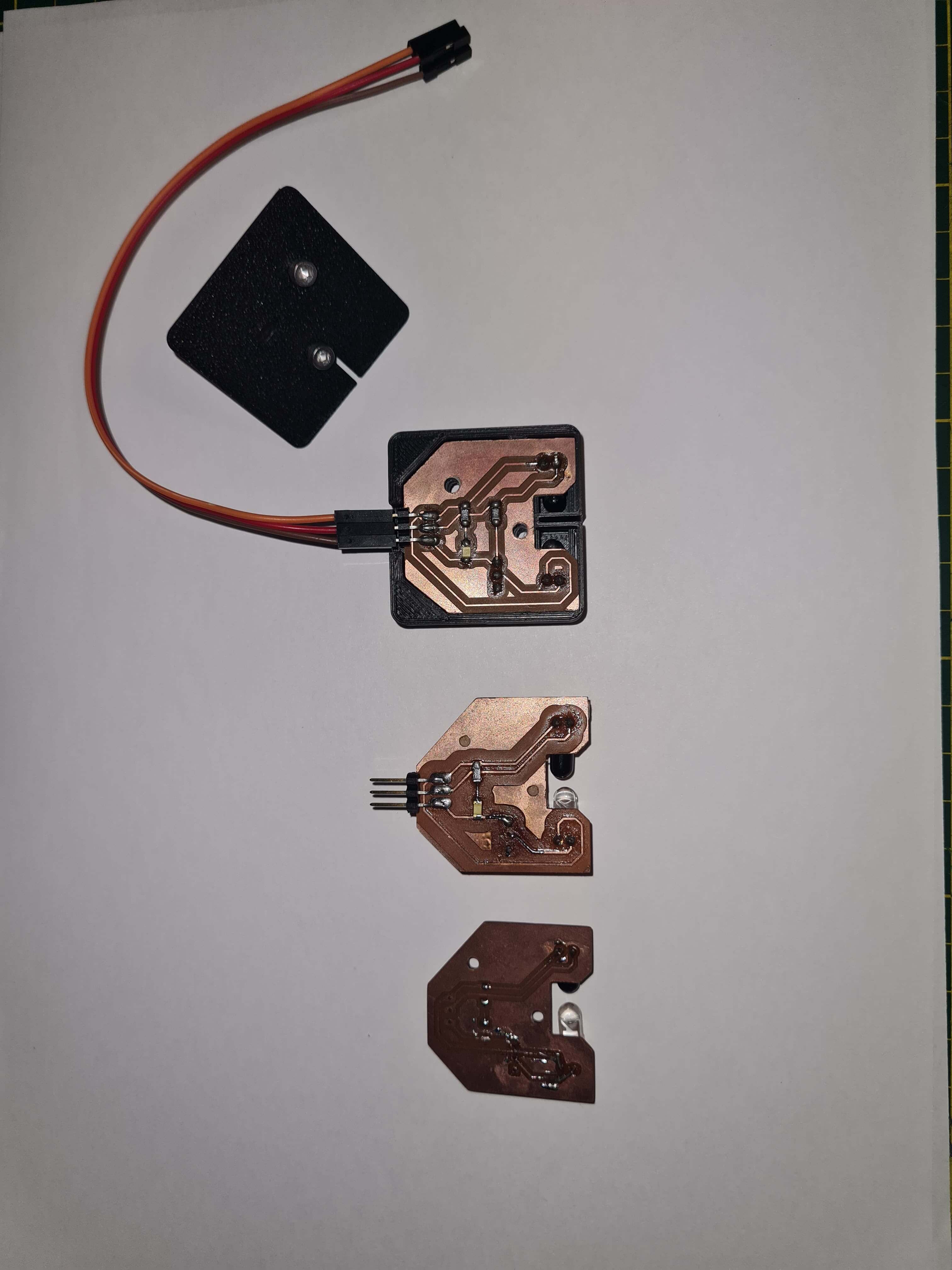
In the first iteration of my design, the PCB pads and traces were too skinny, causing them to break during manipulation. The issues were primarily with the LED and the precision potentiometer. To address this, I utilized the Design Rule Check (DRC) in Fusion 360, as demonstrated during my electronics design week, to increase the surface area of the traces and pads. This adjustment aimed to create a more robust sensor.
Additionally, I had to install the LEDs in a different position to ensure the sensor fit properly within my final project design.
In the next iteration, I successfully resolved all the previous issues. The improved design now features sturdier pads and traces, ensuring better durability and reliability during handling and use.
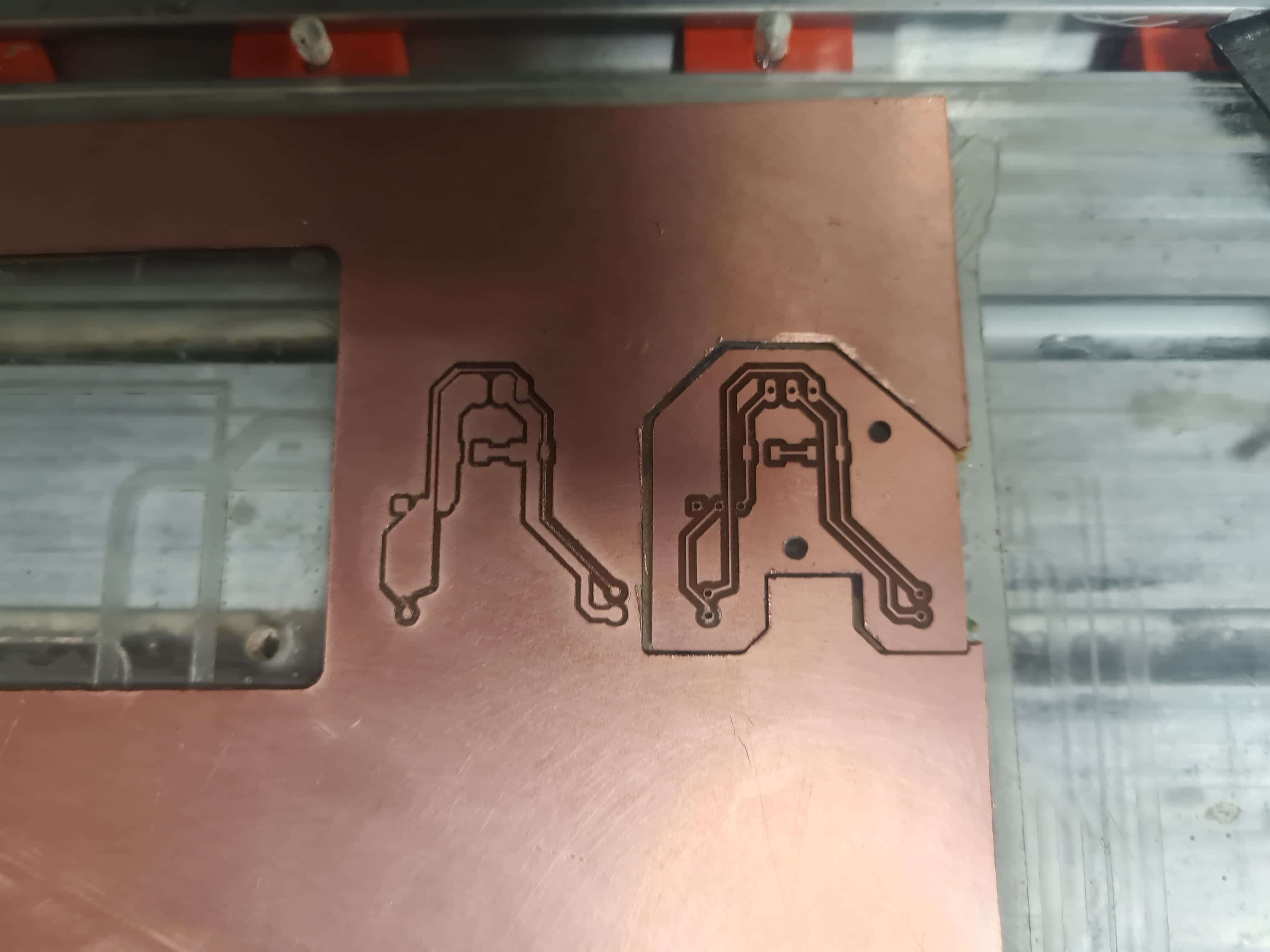
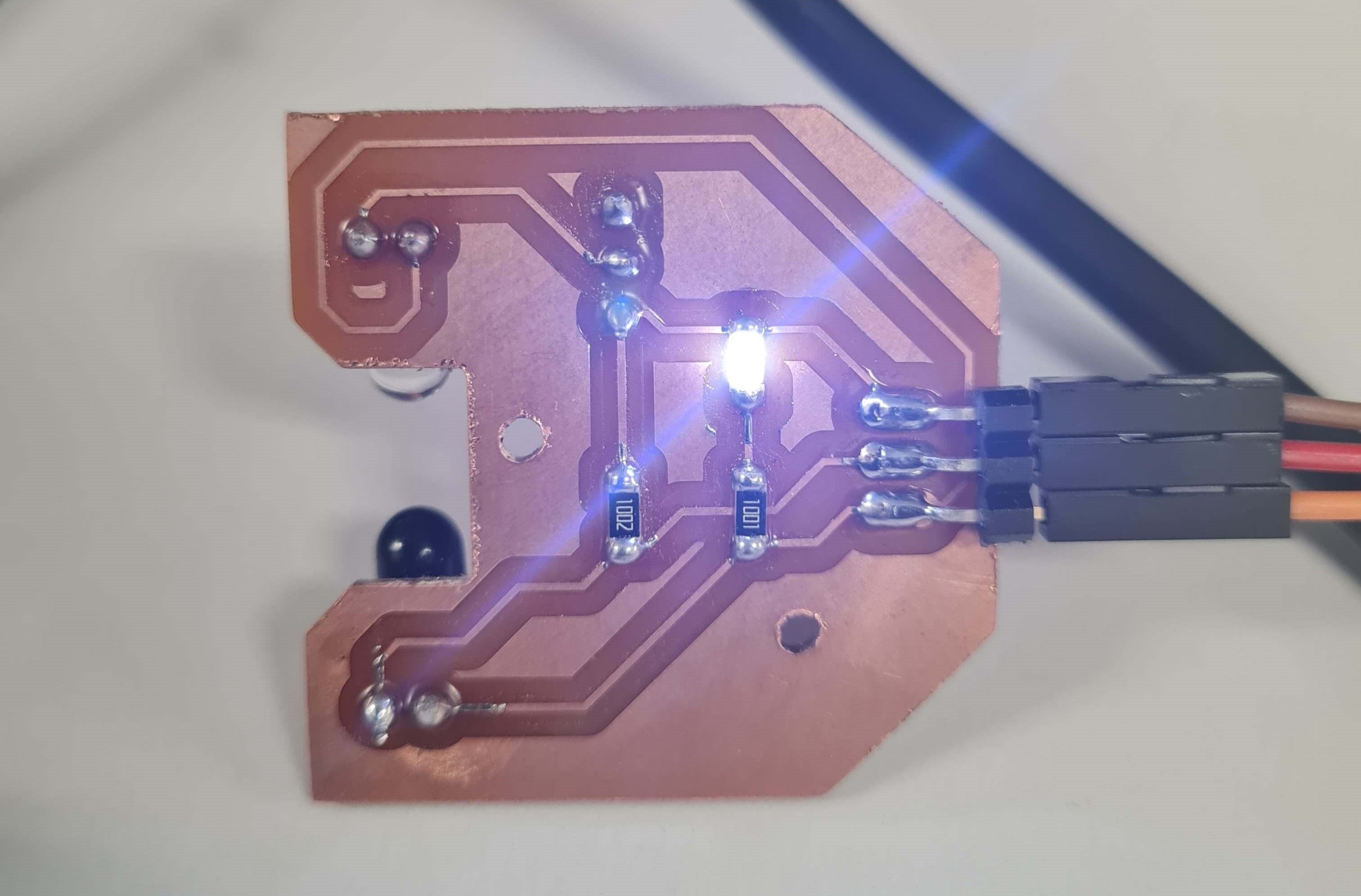
At this stage, I wanted to test the sensor by connecting it to an Arduino Uno and performing a digital read. This sensor is intended for my final project, where it will operate at 3.3V to match the logic voltage of the Xiao microcontroller. Supplying 5V to the Xiao could damage its pins, so it's crucial to use the correct voltage.
To test the sensor, I connected it to the Arduino Uno using the 3.3V supply, GND, and a data pin. I then tested its functionality and calibrated the potentiometer's resistance to adjust the sensitivity as needed.
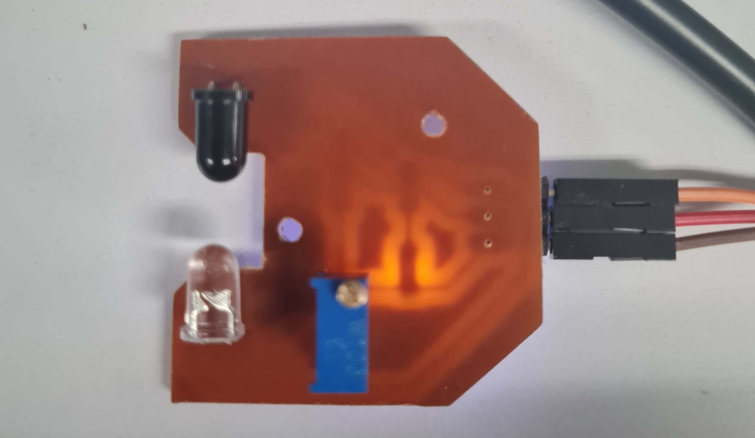
To adjust your IR sensor for use in a 3.3V logic system and configure it to function as a digital sensor, you need to follow a series of steps to ensure accurate detection. The aim is to set the IR LED's brightness using a high-precision potentiometer so that the sensor can reliably detect a 75g piece of paper and operate within the voltage thresholds that define digital HIGH and LOW readings.
In a 3.3V logic system, the digital read function on the microcontroller distinguishes between LOW and HIGH based on specific voltage thresholds. Typically, a voltage close to 0V (generally below 0.3V to 0.8V) is considered LOW, while a voltage close to 3.3V (generally above 2.0V to 2.3V) is considered HIGH. To make the IR sensor work with a digital read, you need to adjust the potentiometer so that the sensor's output toggles between these levels based on the presence or absence of the paper.
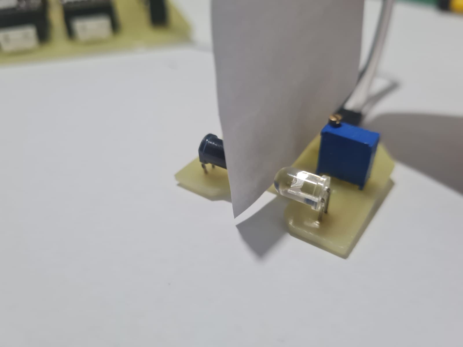
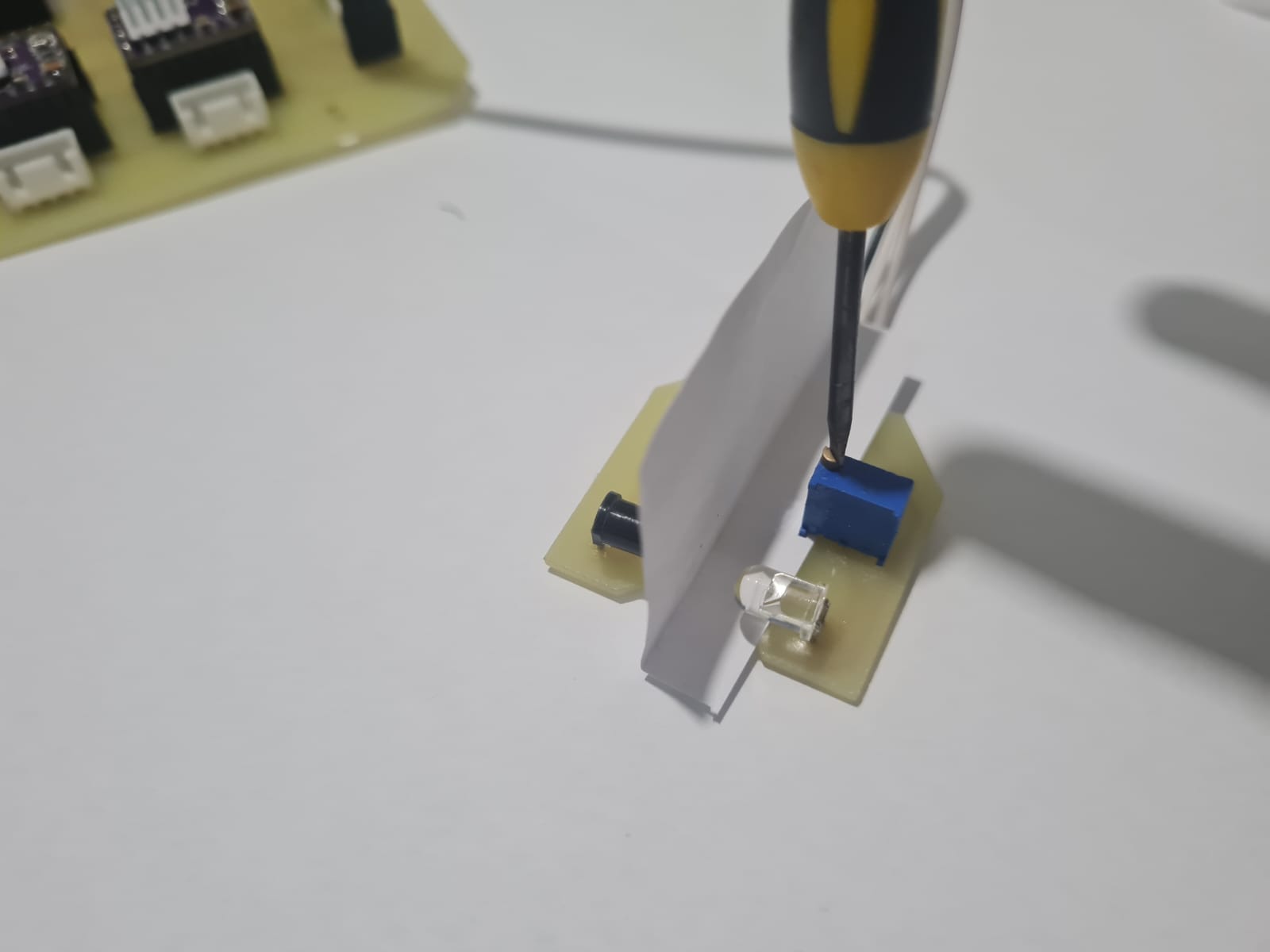
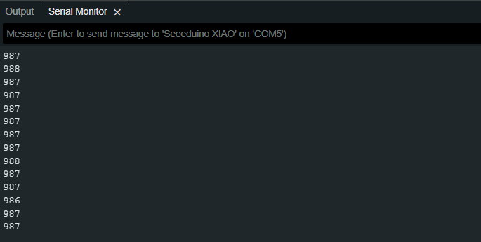
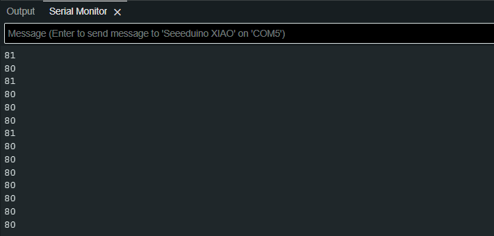
I experimented with the precision potentiometer for calibrating a 75g paper. I adjusted the potentiometer with a screwdriver until the values when triggered were between 700 and 900. When using thin paper, the IR emitter needs to lower the brightness by increasing the resistance of the potentiometer. This adjustment allows the paper to block the specific amount of IR light. If the paper doesn't trigger the sensor, it means the resistance is too low, and the emitter is at near maximum brightness. This amount of light can pass through the paper, preventing the sensor from being triggered correctly. I recommend inserting the piece of paper into the sensor and then adjusting the brightness of the IR emitter until the reading of the sensor is between 700 and 1000.
    // Program Code: IR SENSOR CALIBRATION //

    // Written by: Jorge Suarez de Freitas //

    // Define pin number for IR SENSOR
    int IRSENSOR = 10;


    void setup() {
    // put your setup code here, to run once:

        // Serial communication setup
       Serial.begin(9600);

        // Set pin modes (Input or Output)
        pinMode(IRSENSOR,INPUT);
    }

    void loop() {
    // put your main code here, to run repeatedly:

        //Digital and Analog Readings
        int State = digitalRead(IRSENSOR);    // Testing digital readings
        //int State = analogRead(IRSENSOR); // Calibrating the threshold Target: Untriggered state (60-80) // Triggered State (700-1000)

        //Print sensor reading in the Serial Monitor
        Serial.println(State);
    }
Once the sensor was calibrated to the appropriate range, I switched the reading to digital mode. The following test code is programmed to turn on an LED if the sensor is triggered.
    // Program Code: IR SENSOR Test with LED //

    // Written by: Jorge Suarez de Freitas //

    // Define pin number for IR SENSOR and LED
    int IRSENSOR = 10;       // IR sensor pin
    int LED_PIN = 9;         // LED pin

    void setup() {
    // put your setup code here, to run once:

        // Serial communication setup
        Serial.begin(9600);

        // Set pin modes (Input or Output)
        pinMode(IRSENSOR, INPUT);
        pinMode(LED_PIN, OUTPUT);
    }

    void loop() {
    // put your main code here, to run repeatedly:

    //Variable: State-->Store Sensor Readings
        int State = digitalRead(IRSENSOR);

    //Logic (Triggered-->LED ON // Untriggered-->LED OFF)
        if (State == HIGH) {   // IR sensor HIGH means not triggered (no object)
            digitalWrite(LED_PIN, LOW);  // Turn off LED
        } else {
            digitalWrite(LED_PIN, HIGH);   // Ensure LED is on if sensor is triggered (object detected)
        }
        //Print sensor reading in the Serial Monitor
        Serial.println(State);  // Output sensor state to serial monitor
    }
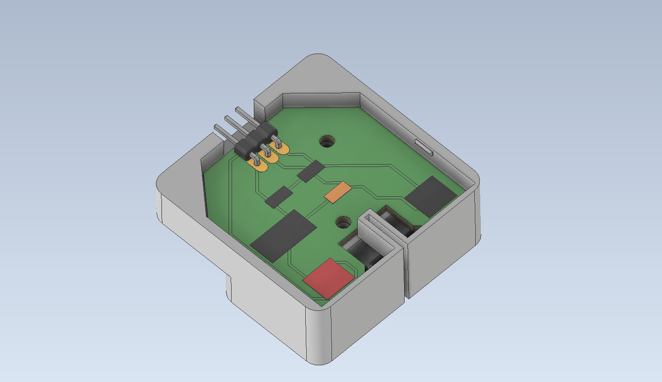
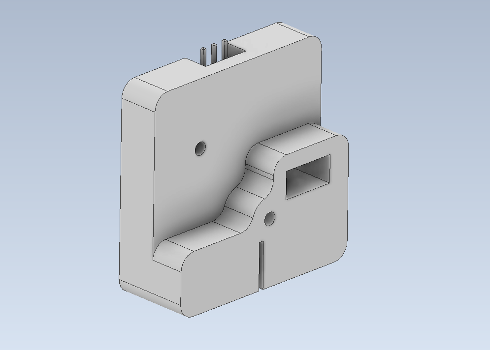
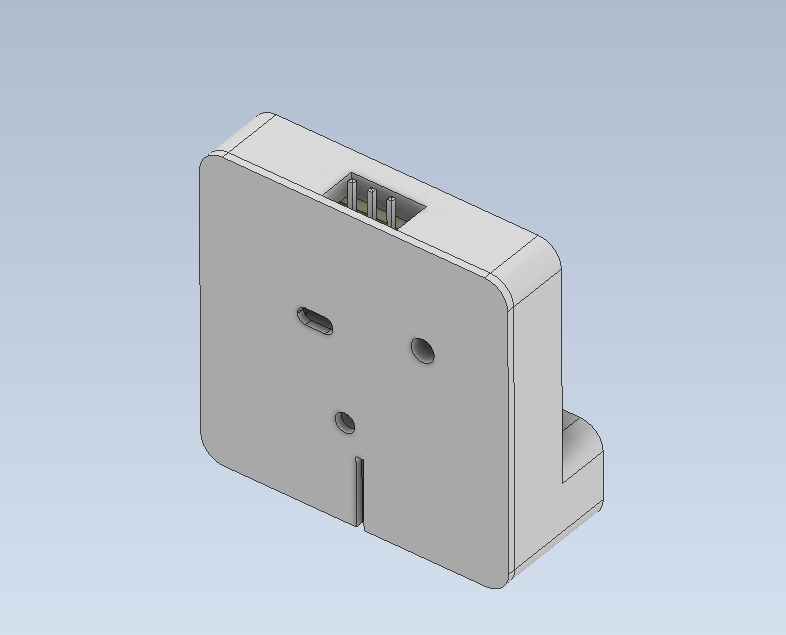
After the PCB design and fabrication were completed, I used the 3D model that Fusion 360 outputs to create a simple case for the sensor in ABS filament.
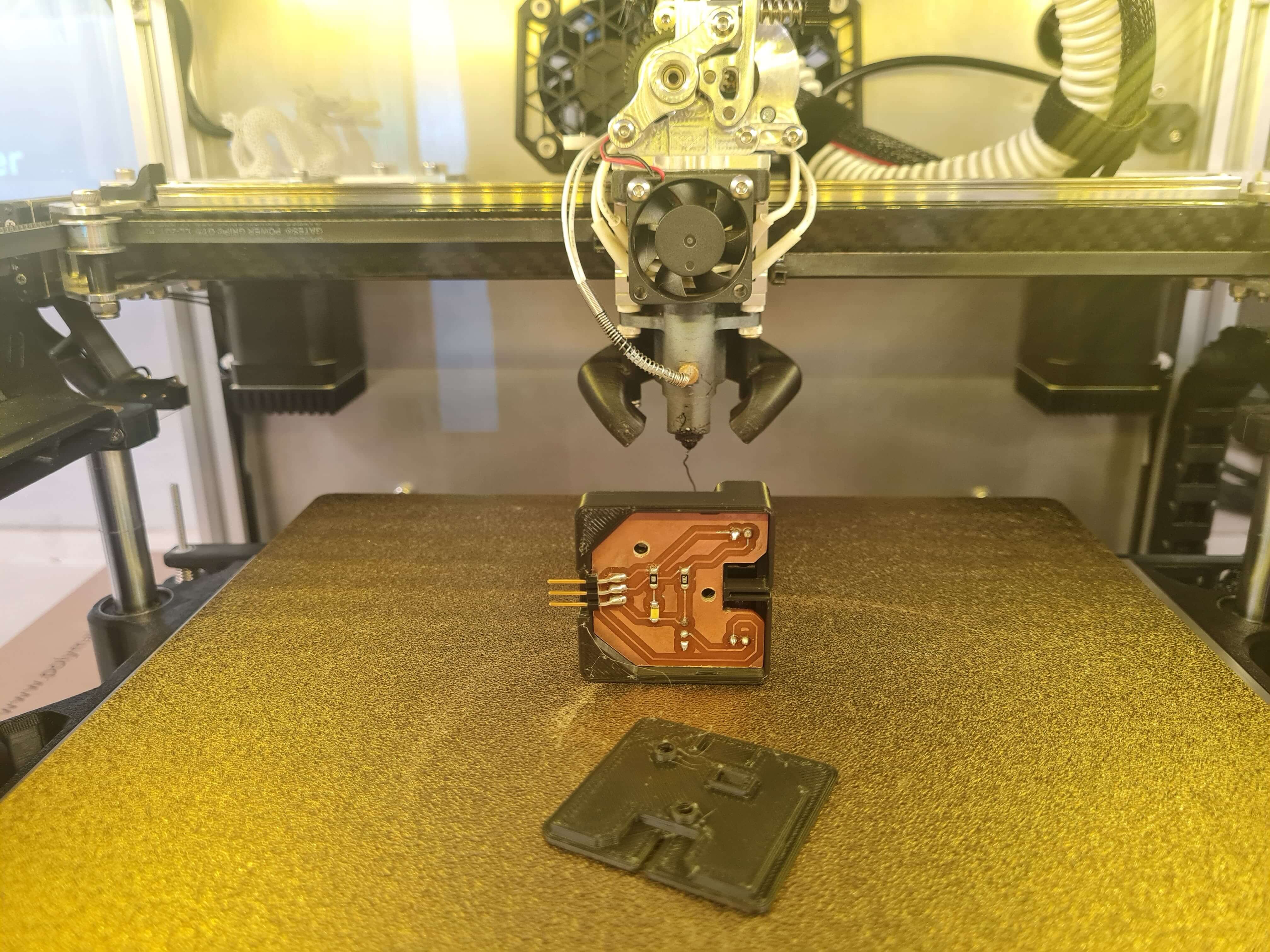
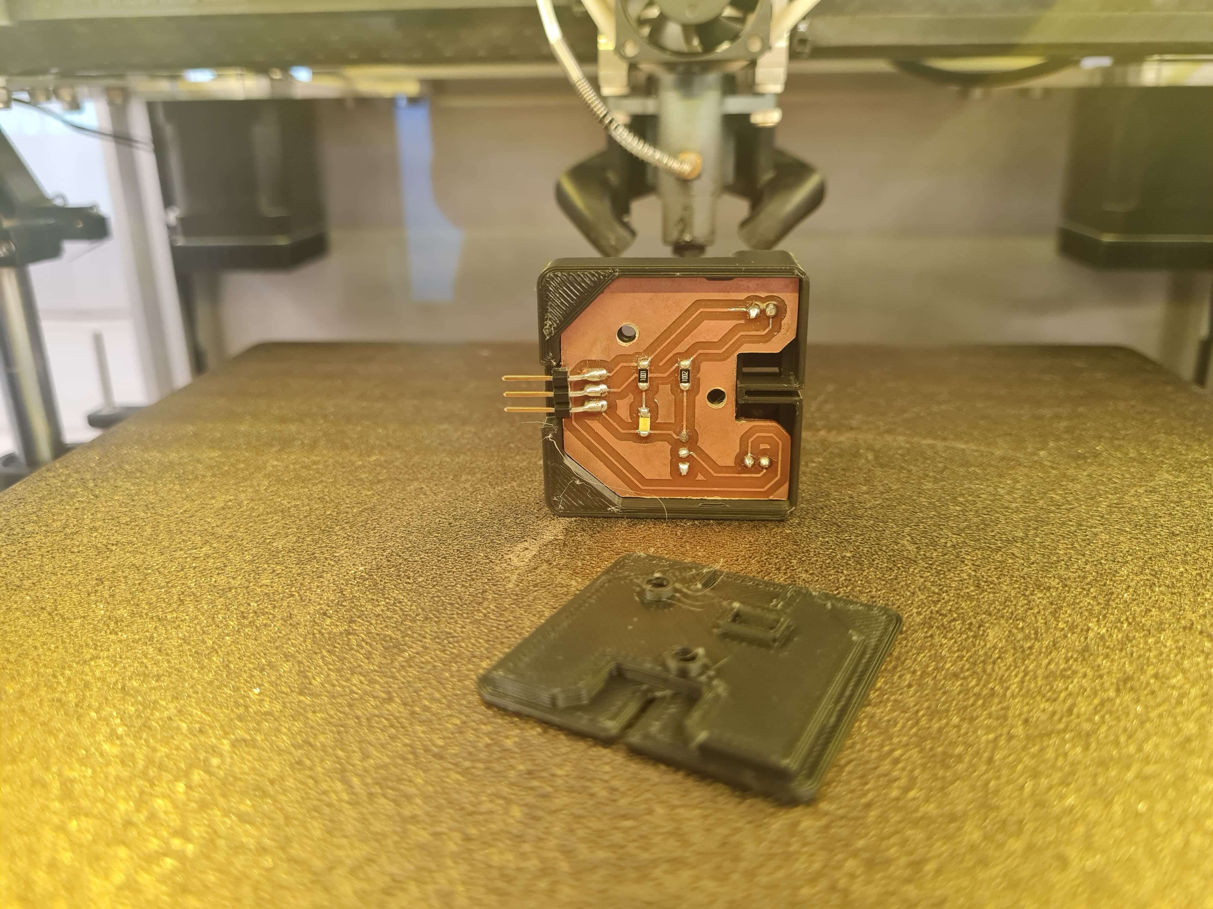
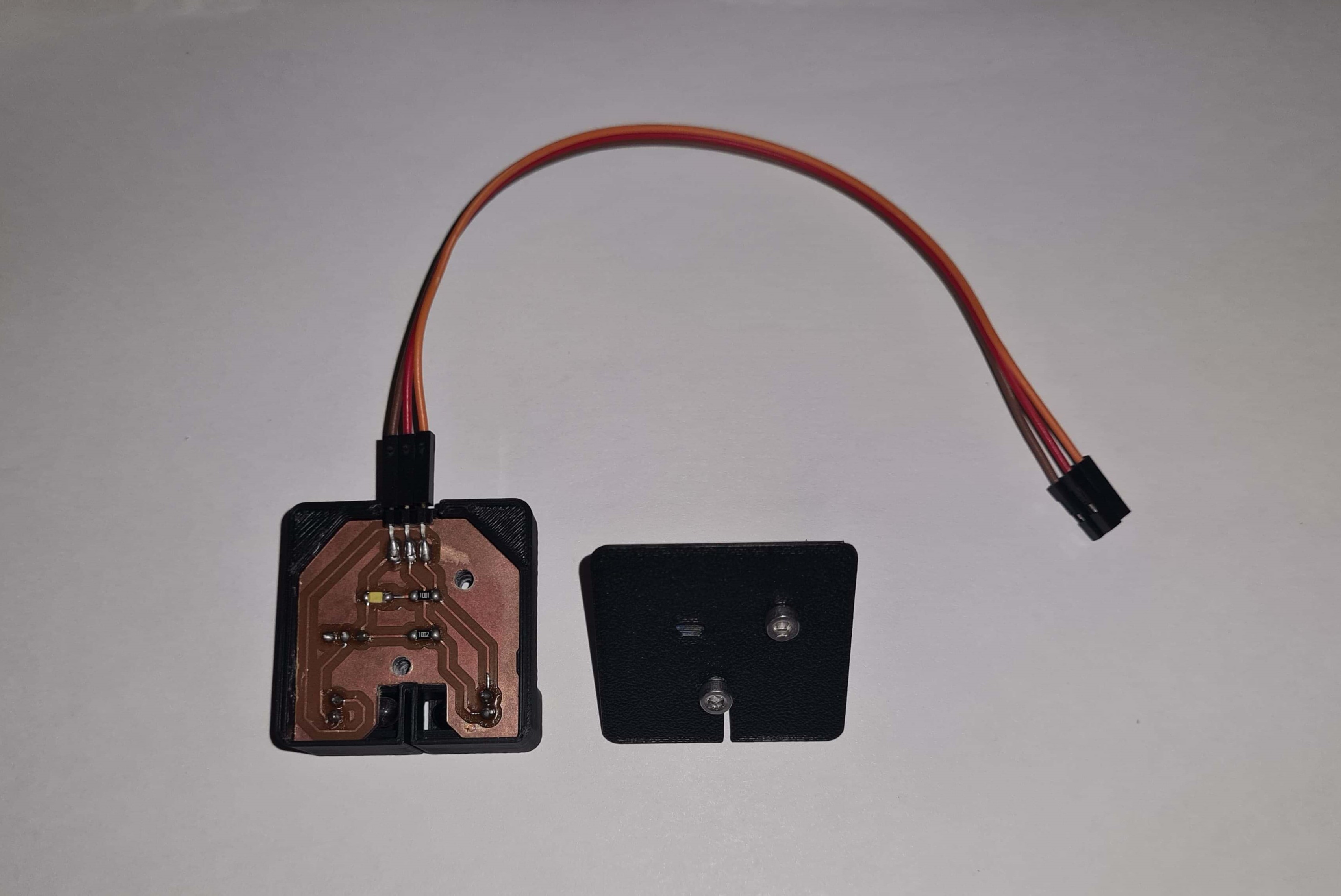
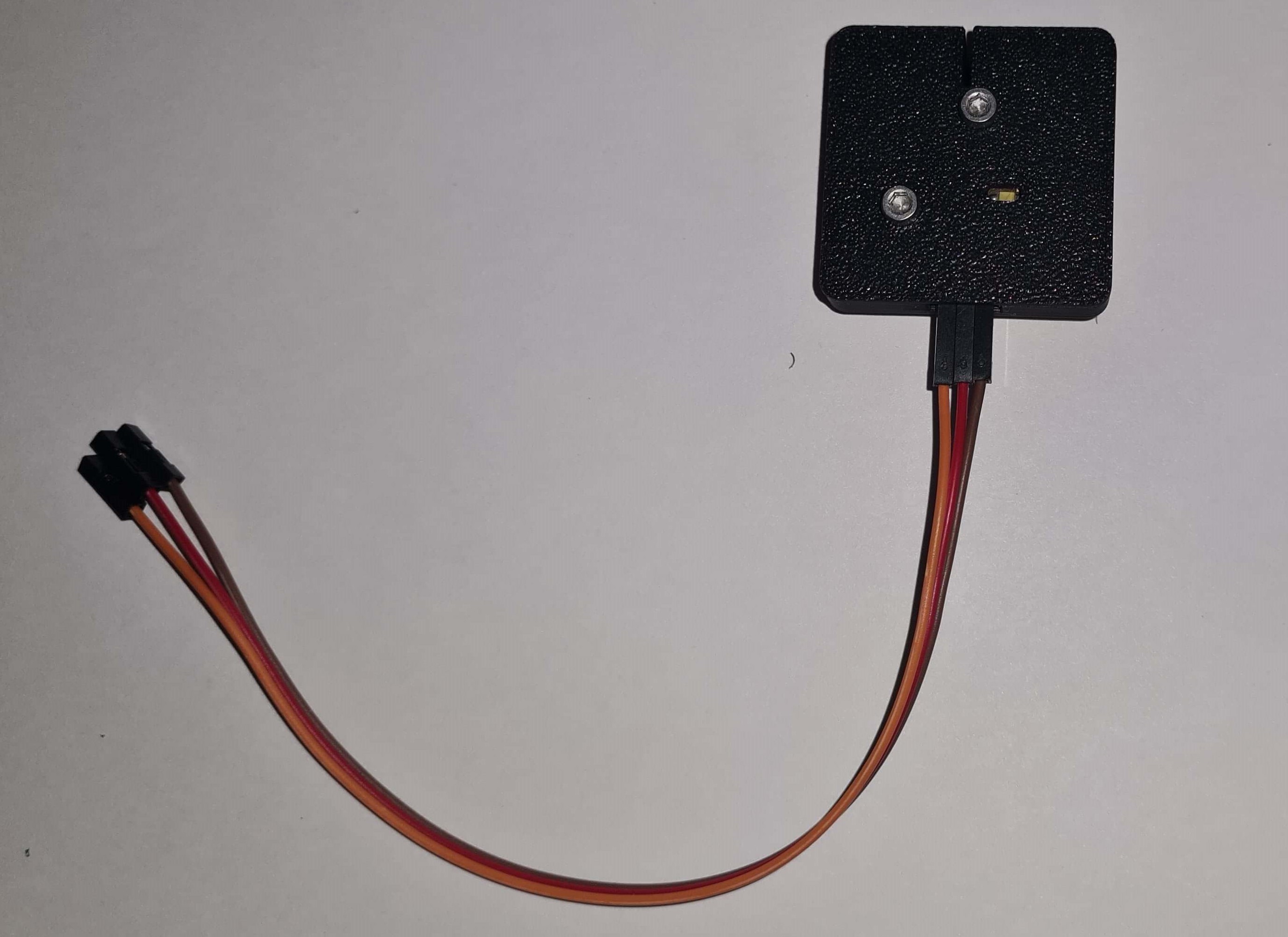
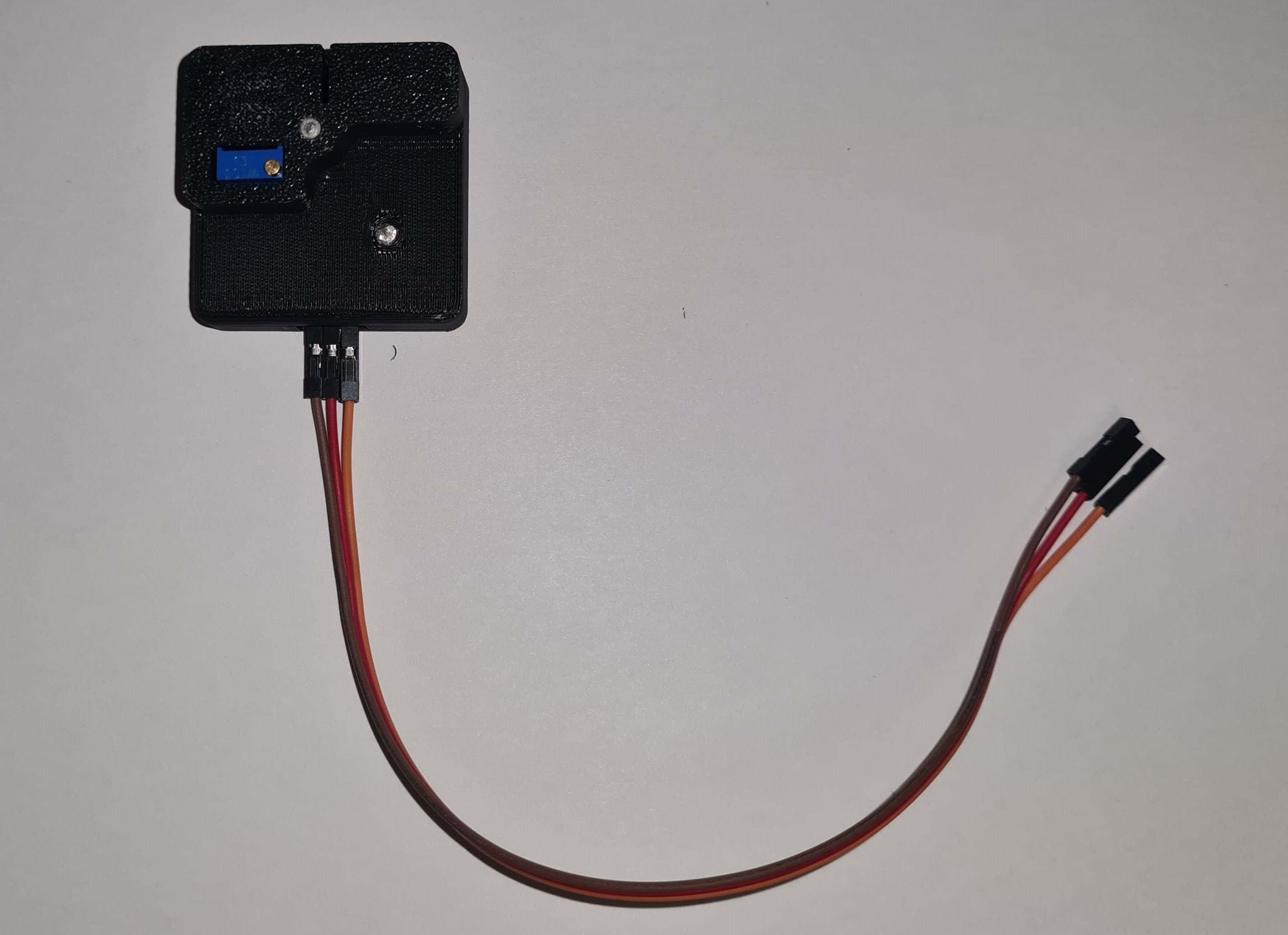
For further testing, I utilized my assignment board from the Output Devices Week, which features an ATtiny44 and a MOSFET. I programmed this board to read the status of the sensor. When the sensor is not triggered, the MOSFET will loop On and Off until the sensor is triggered by a piece of paper. This work aims to familiarize me more with the sensor before integrating it into the final project.
    // Program Code: IR SENSOR CALIBRATION //

    // Written by: Jorge Suarez de Freitas //

    // Define pin number for IR SENSOR and Solenoid
   int IRSENSOR = 10;       // IR sensor pin
   int SOLENOID_PIN = 9;         // Solenoid pin

    void setup() {
    // put your setup code here, to run once:

        // Serial communication setup
        Serial.begin(9600);

        // Set pin modes (Input or Output)
        pinMode(IRSENSOR, INPUT);
        pinMode(SOLENOID_PIN, OUTPUT);
    }

    void loop() {
    // put your main code here, to run repeatedly:

    //Variable: State-->Store Sensor Readings
        int State = digitalRead(IRSENSOR);

    //Logic (Triggered-->Solenoid OFF // Untriggered--> Solenoid ON-OFF Loop)
        if (State == HIGH) {   // IR sensor HIGH means not triggered (no object)
            digitalWrite(SOLENOID_PIN, HIGH);  // Turn on solenoid
            delay(500);                    // Adjust delay as needed
            digitalWrite(SOLENOID_PIN, LOW);   // Turn off solenoid
            delay(500);                    // Adjust delay as needed
        } else {
            digitalWrite(SOLENOID_PIN, LOW);   // Ensure solenoid is off if sensor is triggered (object detected)
        }

        //Print sensor reading in the Serial Monitor
        Serial.println(State);  // Output sensor state to serial monitor
    }
During this assignment, we tested a potentiometer and a switch-type sensor with the Seeeduino ESP32C3 microcontroller. The potentiometer, used as an analog input device, was connected to one of the Seeeduino's four analog pins. We monitored the fluctuating signal using an oscilloscope.
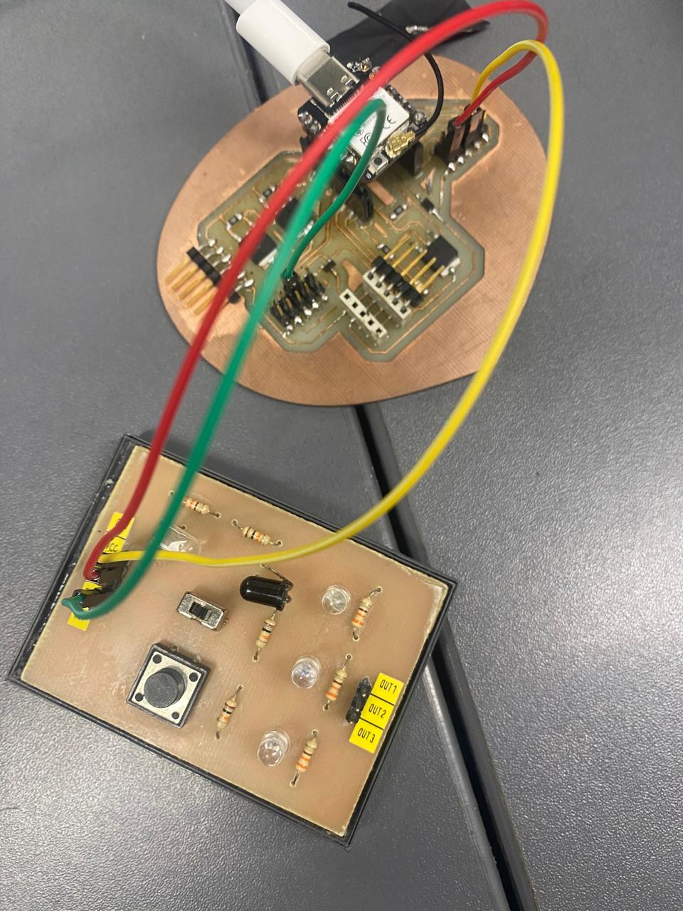
Through this assignment, I gained valuable insights into the differences between analog and digital sensors, as well as the practical applications of ADCs in microcontrollers. The potentiometer's ability to provide a range of voltages and the digital sensor's binary nature both highlight the diverse ways in which input devices can interact with microcontrollers, enhancing our ability to design and implement precise control systems.