Probe an input device analog level and digital signals.
Document your work to the group work page and reflect on your individual page what you learned.
Individual apport
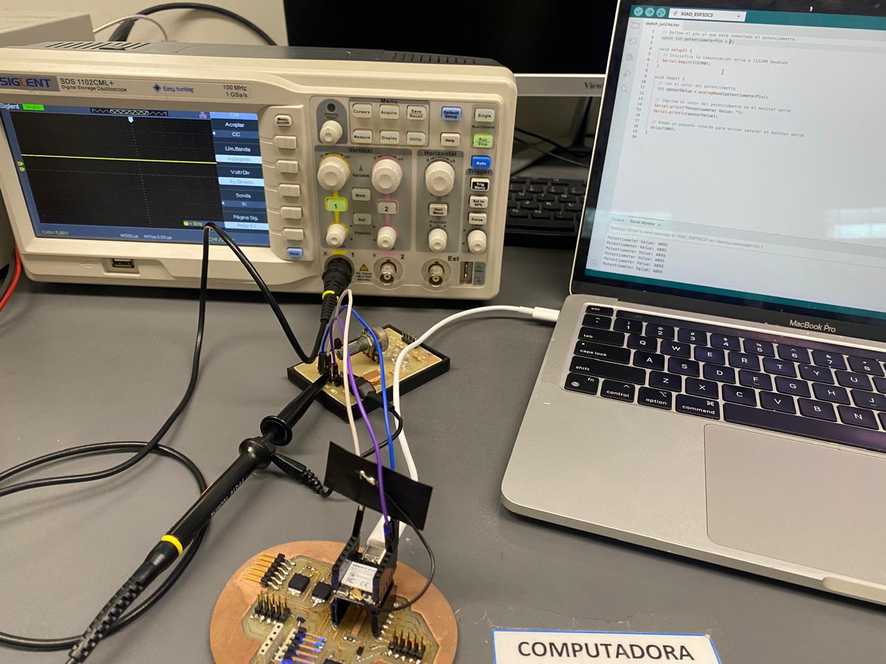
Ernesto, Jorge, Marcela: Our contribution was to test the input signals to the Seeeduino esp32c3 microcontroller and visualize their behavior in terms of their performance on the oscilloscope.
Process
Wiring diagram
Analog Input device
We tested a potenciometer as a analog inpt device in a microcontroller Seeeduino ESP32C3.
This seeeduino has 4 Analog Pins, we used one of them with an
We use an oscilloscope to fluctuate the signal sent to the seeeduino esp32c3
The voltage range with which I worked was from 0 to 5 volts, and its variation could be observed on the oscilloscope.
In the following video you can see how when you turn the knob this voltage goes up, while if you turn it in the opposite direction the delivered voltage goes down.
We tested a potenciometer as a analog inpt device
In contrast to other microcontrollers, the seeeduino ESP32C3 uses a 12-bit ADC, allowing for higher precision and a greater number of resolution divisions. 2 raised to the power of 12 -1 gives us a result of 4095.
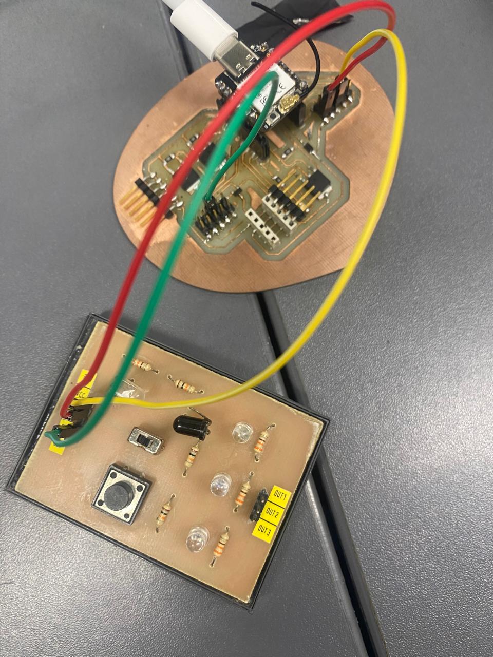
Digital Input device
The input device corresponds to a switch type sensor.
This sensor, being digital, only sends values of 0 or 5 volts, it can only be those two types of values.
.
If it is activated, it sends 5v and if it is not activated it sends 0v
.
This sensor must have 3 connection cables: the first to energize it with 5v, the second to connect it to ground and the last to send the signal in the form of voltage to the seeeduino.
.