Week 12 assignment: Input Devices
Summary
The objective that I had this week was to connect sensors to the board that we had developed and carried out the corresponding programming.
For the assignment I will be testing a button, an ultrasonic distance sensor and a flow sensor to progress with the tests of my final project. I will have to review the technical documentation of these sensors to know how to connect them to my board and finally how to program them.
Process
Button
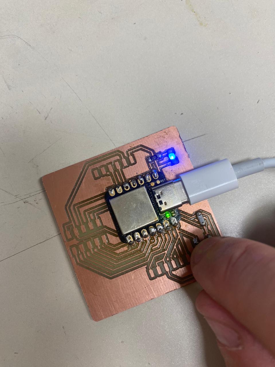
In week 8 I designed a board with a XIAO SAMD21G18 microcontroller and manufactured it with ports available to connect sensors to it. I soldered a button to this board for testing.
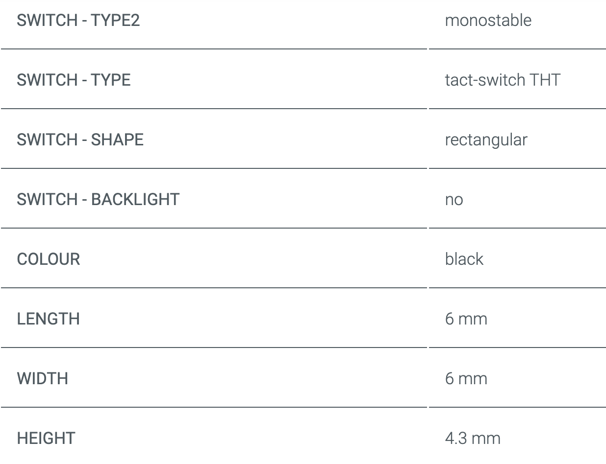
The button I used has the following characteristics:
I had to energize the button with 5 volts through one pin, and through another connect a resistor along with the signal received from my seeeduino microcontroller through port 1.
Ultrasonic sensor
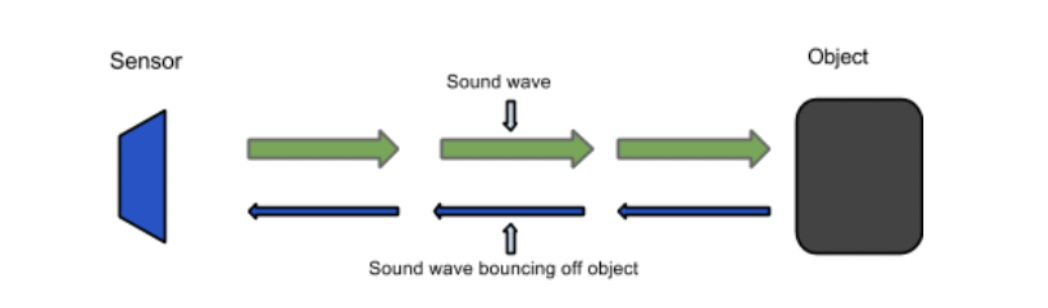
The ultrasonic sensor I used is the HC-SR04. It uses ultrasonic waves to measure distances. It works by emitting an ultrasonic pulse through a transducer and then recording the time it takes to receive the echo of that pulse after it has bounced off an object. By calculating the time it takes for the pulse to travel to the object and back, the sensor can determine the distance to the object with high accuracy.
Here are its technical characteristics :
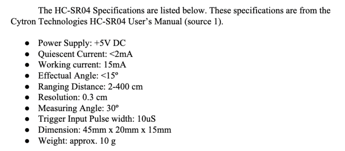
The HCSR04 has four pins, VCC, GND, TRIG and ECHO; these pins all have different functions. The VCC and GND pins are the simplest they power the HCSR04.These pins need to be attached to a +5 volt source and ground respectively. There is a single control pin: the TRIG pin. The TRIG pin is responsible for sending the ultrasonic burst. This pin should be set to HIGH for 10 μs, at which point the HCSR04 will send out an eight cycle sonic burst at 40 kHZ. After a sonic burst has been sent the ECHO pin will go HIGH. The ECHO pin is the data pin it is used in taking distance measurements.
After an ultrasonic burst is sent the pin will go HIGH, it will stay high until an ultrasonic burst is detected back, at which point it will go LOW. Taking Distance Measurements The HCSR04 can be triggered to send out an ultrasonic burst by setting the TRIG pin to HIGH. Once the burst is sent the ECHO pin will automatically go HIGH. This pin will remain HIGH until the the burst hits the sensor again. You can calculate the distance to the object by keeping track of how long the ECHO pin stays HIGH. The time ECHO stays HIGH is the time the burst spent traveling. Using this measurement in the following equation along with the speed of sound will yield the distance travelled.
D = V x T (Distance = Velocity x Time)
Finally, using the speed of sound (which is 343 meters per second at standard temperature and pressure) we can use the following formula to calculate the distance
D = Time / 58 (Centimeters)
The wiring is quite simple, following the specifications mentioned before. I have connected the trig to port 3, and the echo to port 2 of the seeeduino.
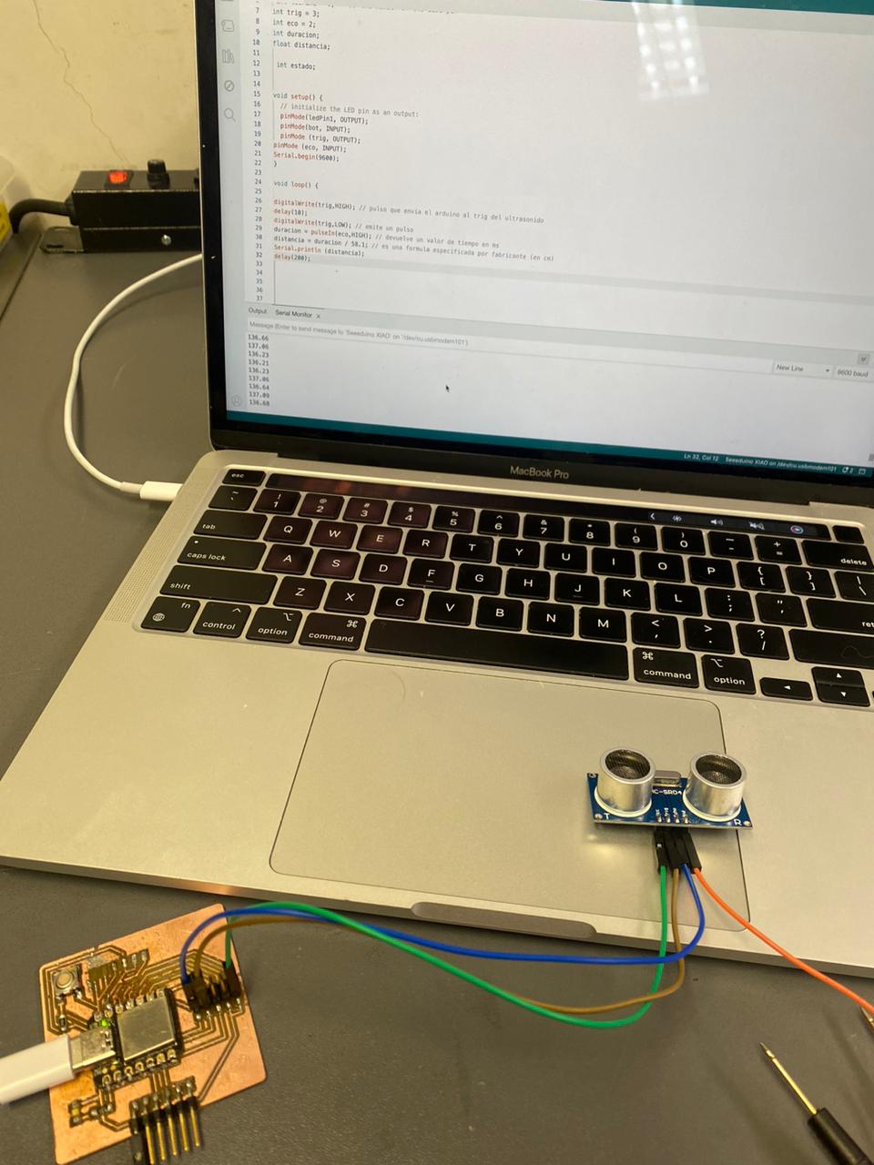
Below is the programming code in Arduino environment:

Flow sensor
Finally, I used a flow sensor to measure the flow rate that circulates through the hose. The technical specifications are as follows:
Specification:
Material: Plastic
Color: White
Function: Sensor, flow control
Flow rate: 0.3 ~ 3 L/min
Flow pulse: F(Hz) = (109 x Q) L/min ± 5%
Max operating current: 15mA (DC 5V)
Minimum working voltage: For DC 4.5V
Operating voltage: For DC 5V ~ 24V
Load capacity: ≤ 10mA (for 5V)
Pressure: 0.8 mPa
Operating temperature: -25 ~ +60°C
1 liter of water = 7055 Pulses ± 10%
Accuracy: ± 5%
Working environment: Water, liquid, light oil, beer, drinking water
Connection tube diameter: 6mm or 1/4"
Inner diameter: 5.84mm/0.23"
Outer diameter: 12.2mm/0.48"
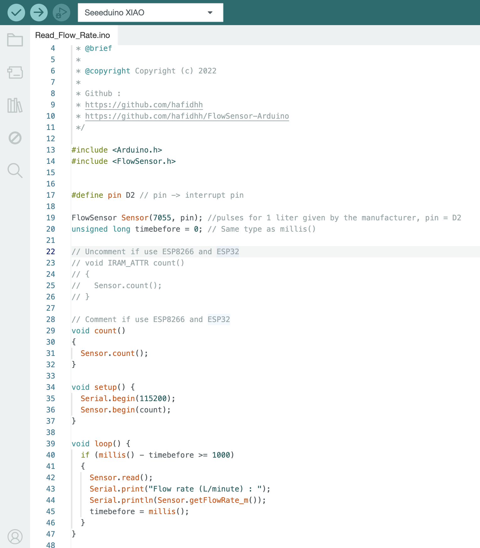
With the frequency information (7055 pulses / liter of water) and using the Arduino IDE Flow.h library I was able to determine the flow rate that circulates through this sensor. i used the port 2 of the seeeduino, 5v for power the sensor and GND from the sensor to the board. Here you can see the code:
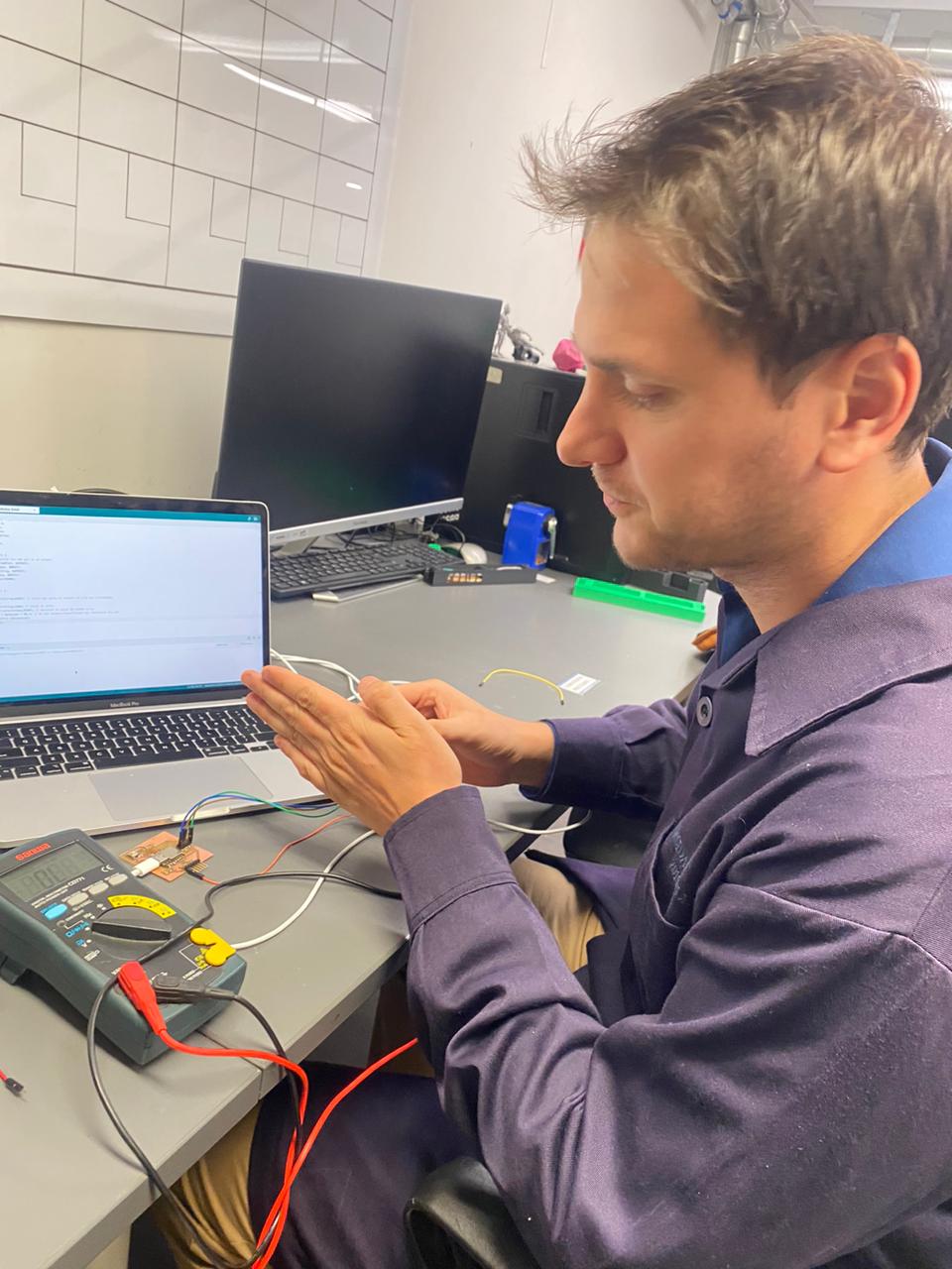
With the code working fine, I did the test by filling a bottle with water in a certain time to calculate the flow and it gave me results consistent with those printed on the serial monitor.

Group assignment
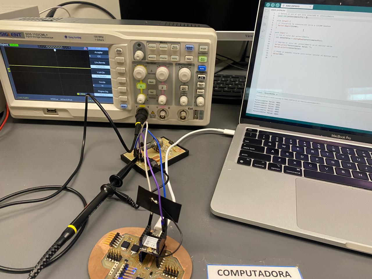
What I learned was how an analog and a digital sensor behaved on the oscilloscope. While one varied its range from 0-5 volts, and could have intermediate values, the digital one only allowed signals of 0 or 5 volts to be read, with the possibility of only those two states.
My contribution to the group work was to test the input signals to the Seeeduino esp32c3 microcontroller and visualize their behavior in terms of their performance on the oscilloscope.
Here is the link to the group assignments:
Files: