OUTPUT DEVICES
Let's move something
Group assignment
The group's tasks:measure the power consumption of an output device fablab website.
General Objective
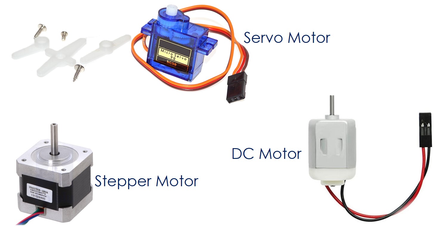
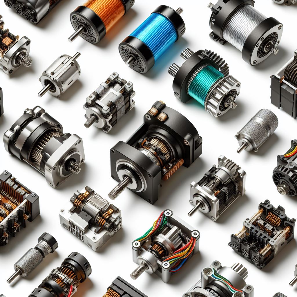
The idea is to explore the main engines used in DIY projects, the types that exist, the technologies they use, some popular libraries for their use, as well as other data of interest.
DC motors
DC motors stand out for their ability to convert electrical energy into rotational mechanical force. This conversion is achieved through the dynamic interaction of electrical conductors and magnetic fields. There is a wide range of these motors available, with brushed and brushless models being the most widespread on the market.
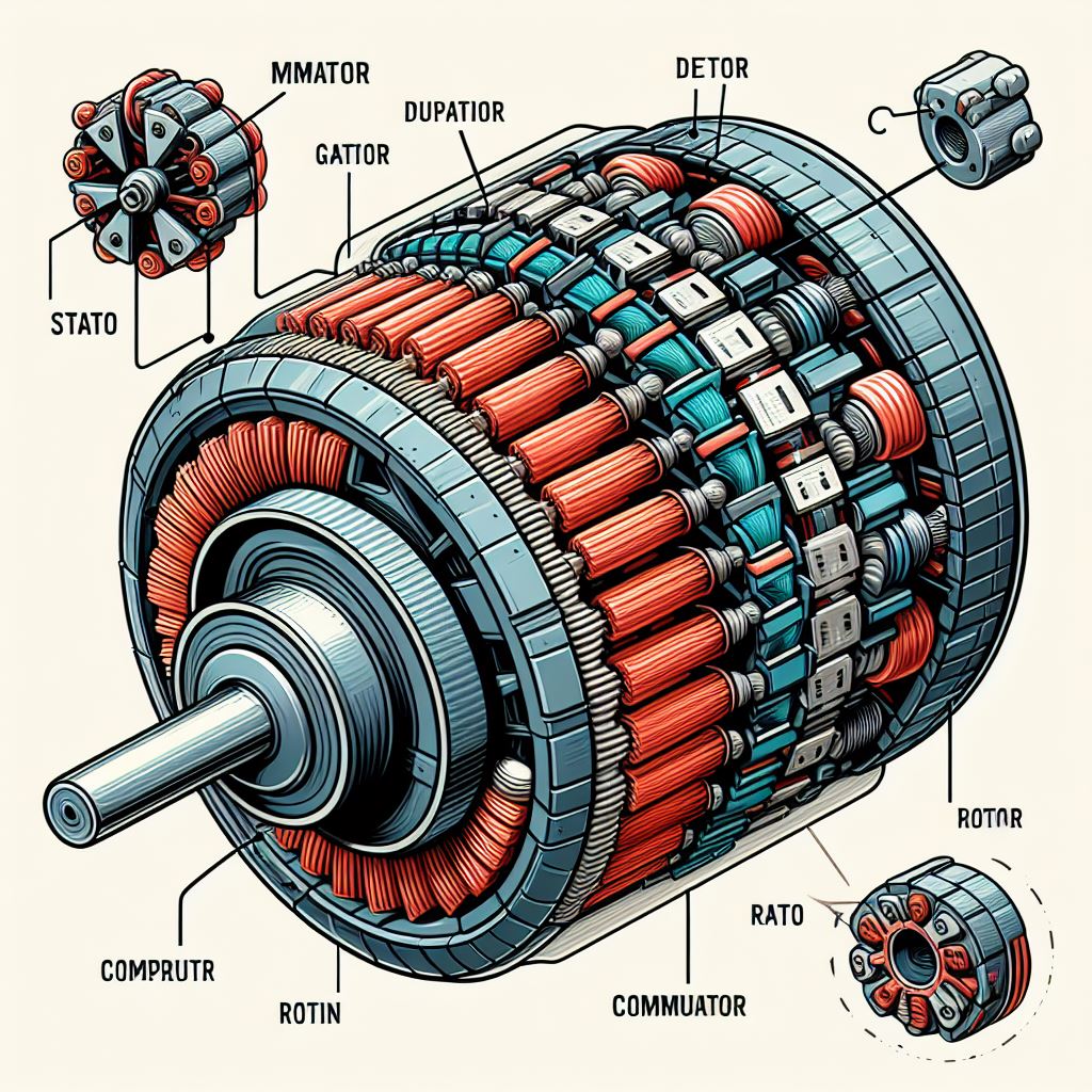
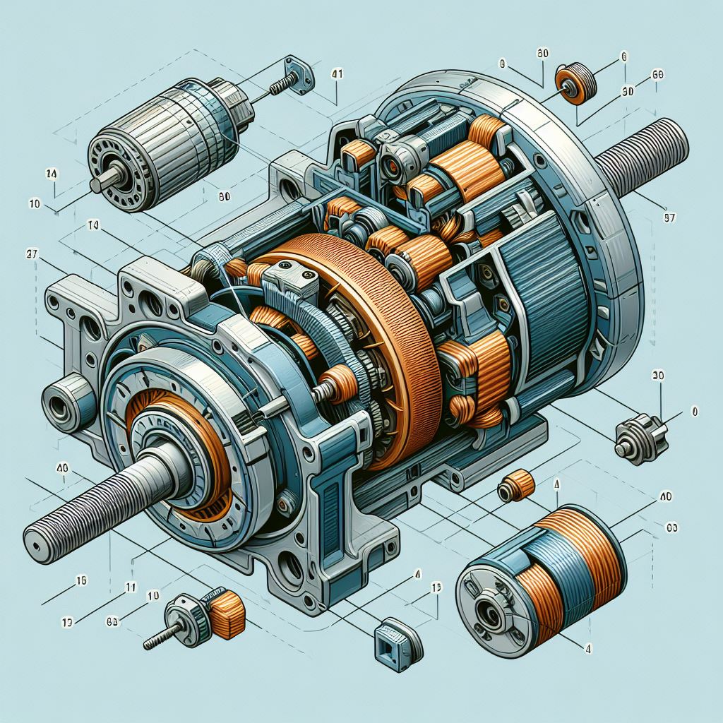
A direct current (DC) motor works by converting electrical energy into mechanical energy. The process is based on the interaction between a stationary magnetic field, generated by the stator, and a rotating magnetic field, created by the current flowing in the rotor coil. When electric current passes through the coil, a torque is induced due to Lorentz's law, causing the rotor to rotate. The commutator, together with the brushes, reverses the direction of the current in the rotor coil at regular intervals, ensuring that the rotary motion is continuous and in a single direction. This design allows the DC motor to be efficient and precise in controlling motor speed and torque.
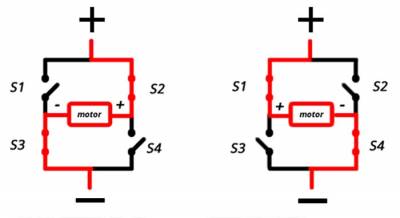
An H-bridge is an electronic circuit used to control direct current (DC) motors. Its design allows you to change the polarity of the voltage applied to the motor, which in turn allows you to control the direction of rotation of the motor, either forward or reverse. The name “H bridge” comes from the typical circuit configuration, which resembles the letter “H” on a schematic diagram. In an H-bridge, four switches (transistors, relays or MOSFETs) are placed in a formation that allows them to be activated in opposite pairs to reverse the direction of the current and, therefore, the direction of rotation of the motor. Additionally, the H-bridge can be used to control motor speed using pulse width modulation (PWM), making it an essential tool in robotics and automation.
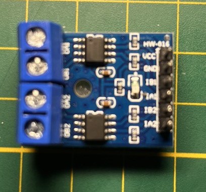
The L9110 DC motor driver is a compact and economical module used to control DC motors. This driver is capable of driving two small DC motors simultaneously or one small stepper motor. It operates with an input voltage of 2.5 to 12V DC and can supply a continuous current of 800 mA per channel12. Its H-bridge design allows the polarity of the voltage applied to the motor to be reversed, making it easier to change the direction of motor rotation. In addition, it is compatible with various microcontrollers such as Arduino, Raspberry Pi, ESP32, among others, making it ideal for robotics and automation projects.
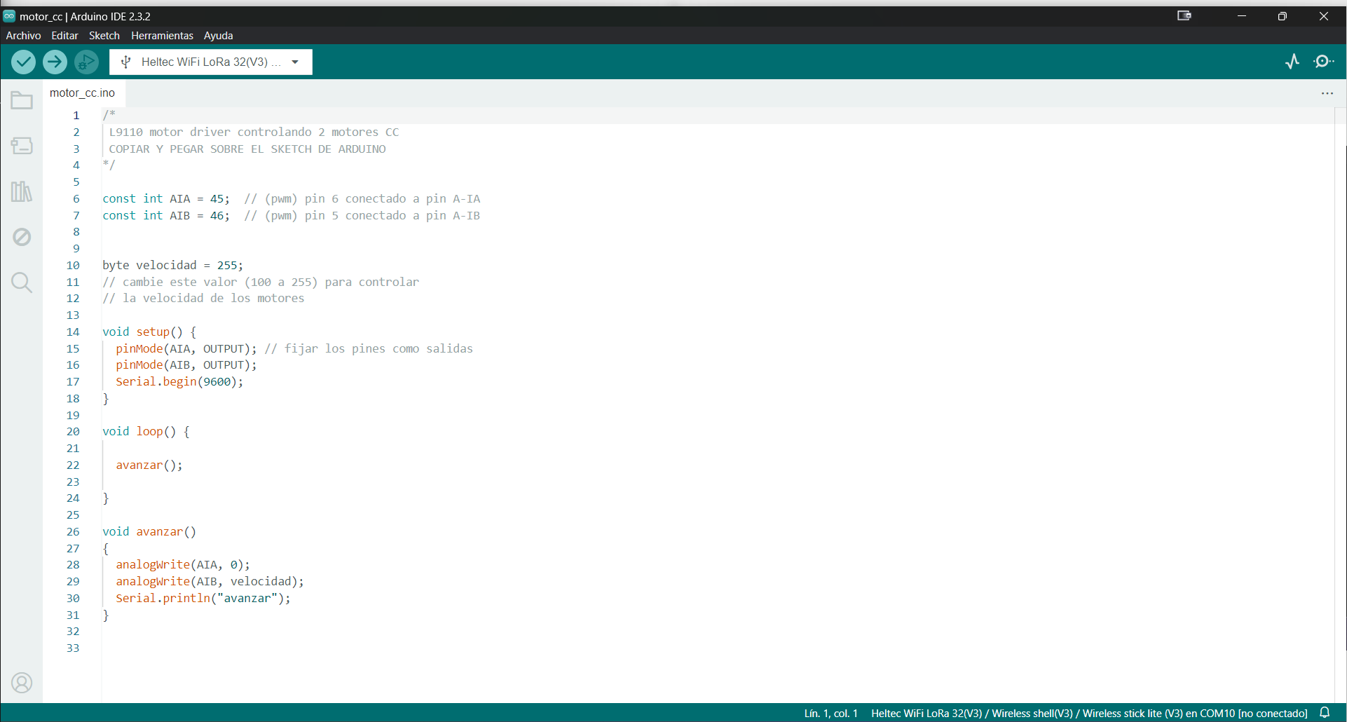
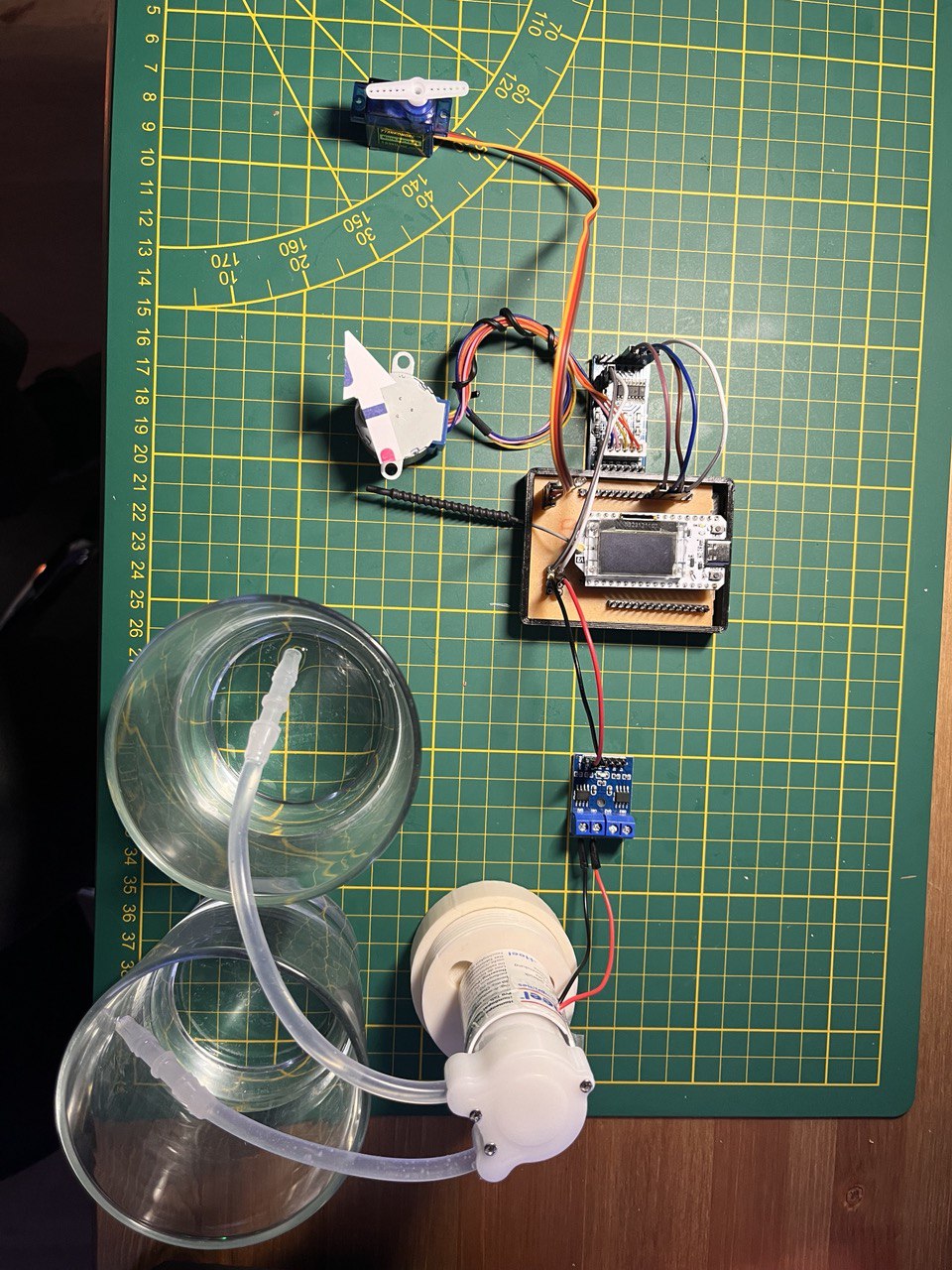
To make the program in Arduino I did not use any library, and although I could have varied the speed of the motor I did not do so, I made a default speed configuration, so that it would work at maximum speed, and as simple as if it were an LED. Periodically turn on the pump.In this link is the code.
To test the motor I decided on something simple, a motor in the format of a water pump, while in an on-off program the water is passed from one container to another.
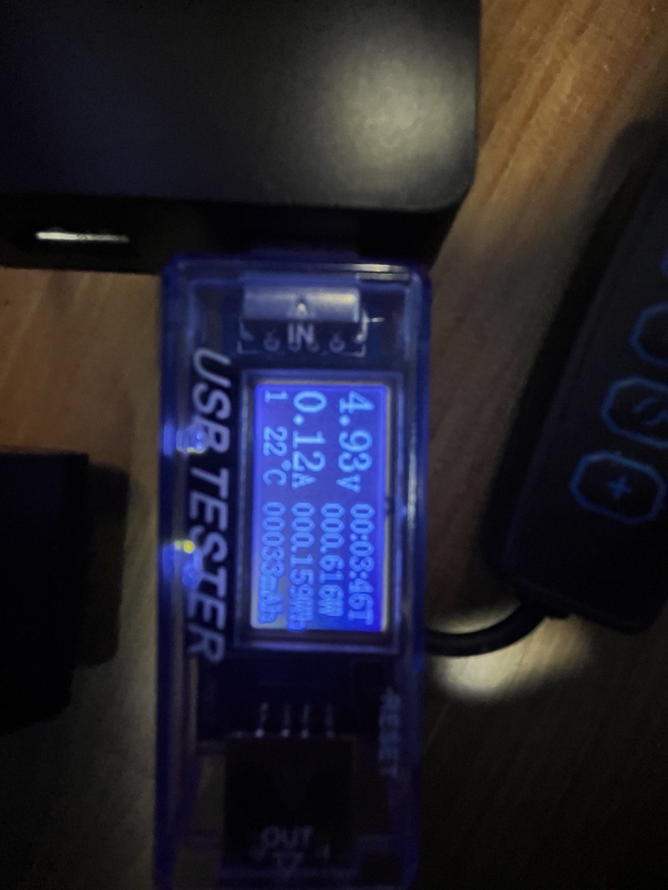
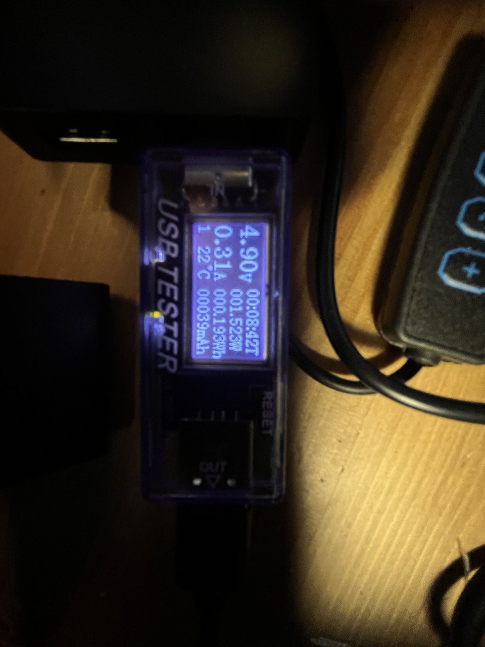
Using this sensor we can see the system consumption at the time the previous video was taken.
Stepper motors
Stepper motors are devices that advance in slow, precise and discrete steps. Prized for their precise position control, they are used in a wide range of applications, including desktop printers, security cameras and CNC milling machines.
A stepper motor is made up of a rotor, which is the rotating part, and a stator, which contains the coils and is the stationary part. The stator generates magnetic fields that interact with the rotor to produce motion. The rotor usually has permanent magnets or iron teeth that react to the magnetic fields of the stator. The operation of the motor is based on the sequential activation of the stator coils through a series of electrical pulses. Each pulse advances the rotor one step, which is a fraction of a full turn. The activation sequence of the coils determines the direction of rotation and the type of step (full, half, etc.). Stepper motors are ideal for applications requiring precise position and speed control, such as in robotics and CNC machinery.
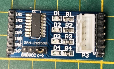
The ULM2003 is a stepper motor driver notable for its ability to handle higher currents and voltages than a typical microcontroller can supply. It is ideal for robotics and automation projects where precise control of movement is required. The ULM2003 allows easy interface with a wide range of stepper motors, providing a versatile and efficient solution for applications requiring fine position and speed adjustments. Its robust design and ability to operate over a wide temperature range make it reliable for use in industrial and commercial environments. Additionally, its ease of use and low cost make it a popular choice among hobbyists and professionals alike.
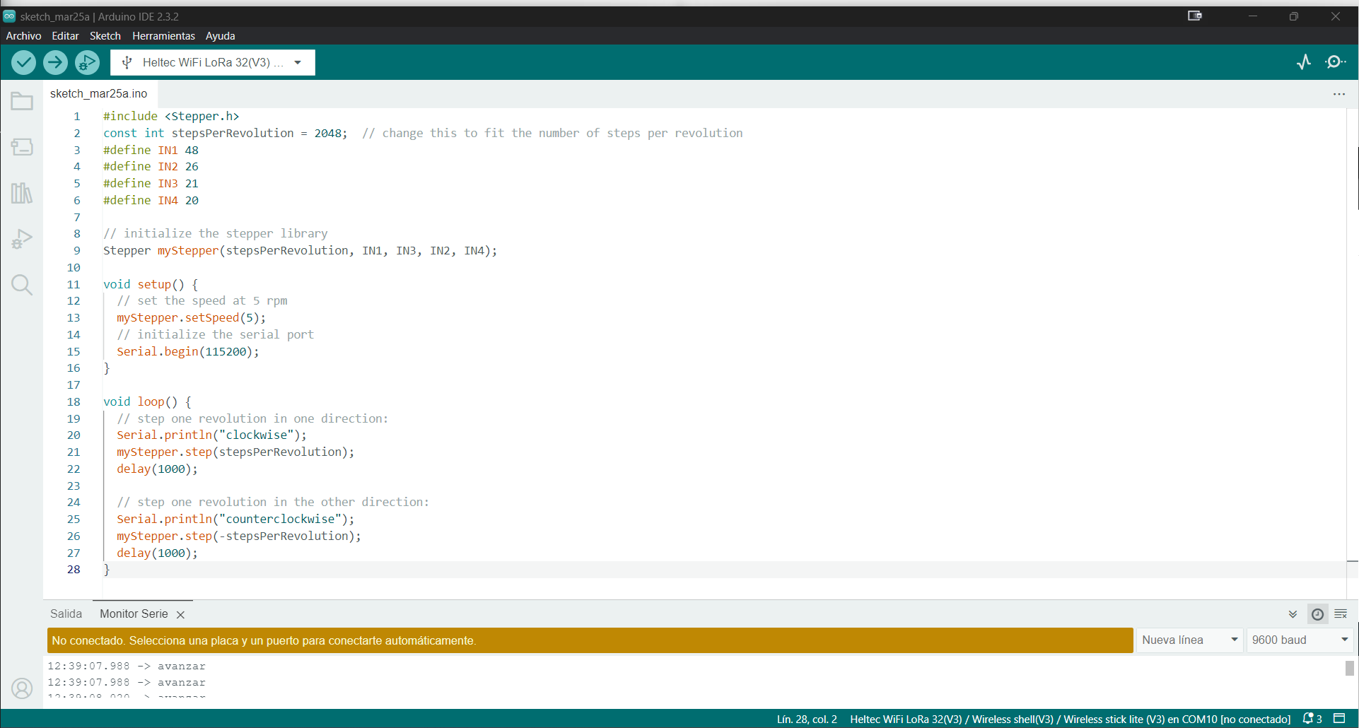
There are many libraries, but on this occasion I used the most general one, as we can see at the beginning of the code the steps per revolution are configured (manufacturer's data) and the pins to which it will be connected.In this link is the code.
As the code describes, the motor will move in 1 second intervals clockwise and then counterclockwise.
With the same device we measure its energy consumption; with the use of this type of device it is always necessary to use an external power source.
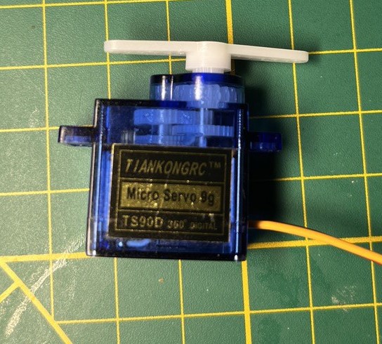
Servo motors
Servo motors are motors capable of providing very precise motion control. The feedback in a servo motor system senses the difference between the actual and desired speed or position so that the controller can adjust the output to correct any drift from the target position. The positional rotation and continuous rotation are two basic types of servo motors.
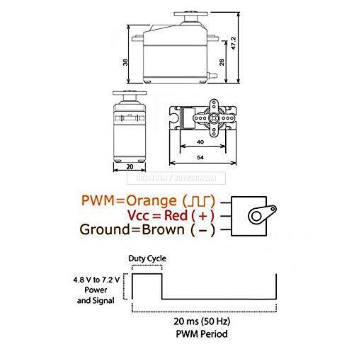
A servomotor is an electromechanical device used to provide precise control of angular position, speed and acceleration. It consists of a suitable electric motor, a set of gears, and a feedback control circuit. The circuit receives a control signal, usually in the form of pulse width modulation (PWM) pulses, which determines the desired position of the motor. As the motor moves toward that position, a feedback sensor, such as a potentiometer or encoder, sends signals back to the control circuit to adjust the movement and achieve the exact position required.
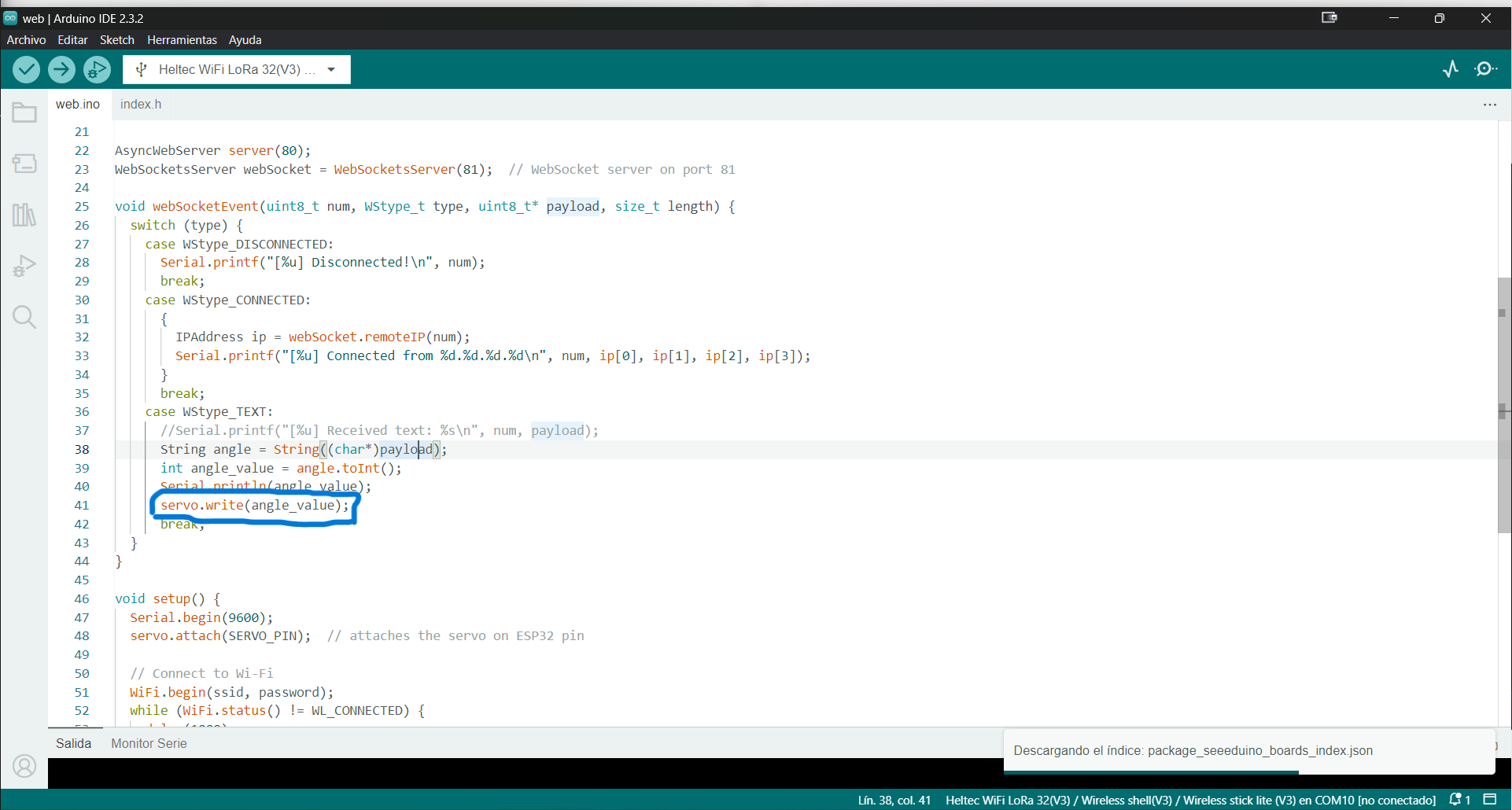
In this selected fragment of the code, we can see how by simply modifying the PWM value of a PIN I can control the speed of the servo motor, as this code also contains a website.In this link is the code.
As can be seen by moving that web potentiometer that creates I can vary the speed of the motor or stop it completely.
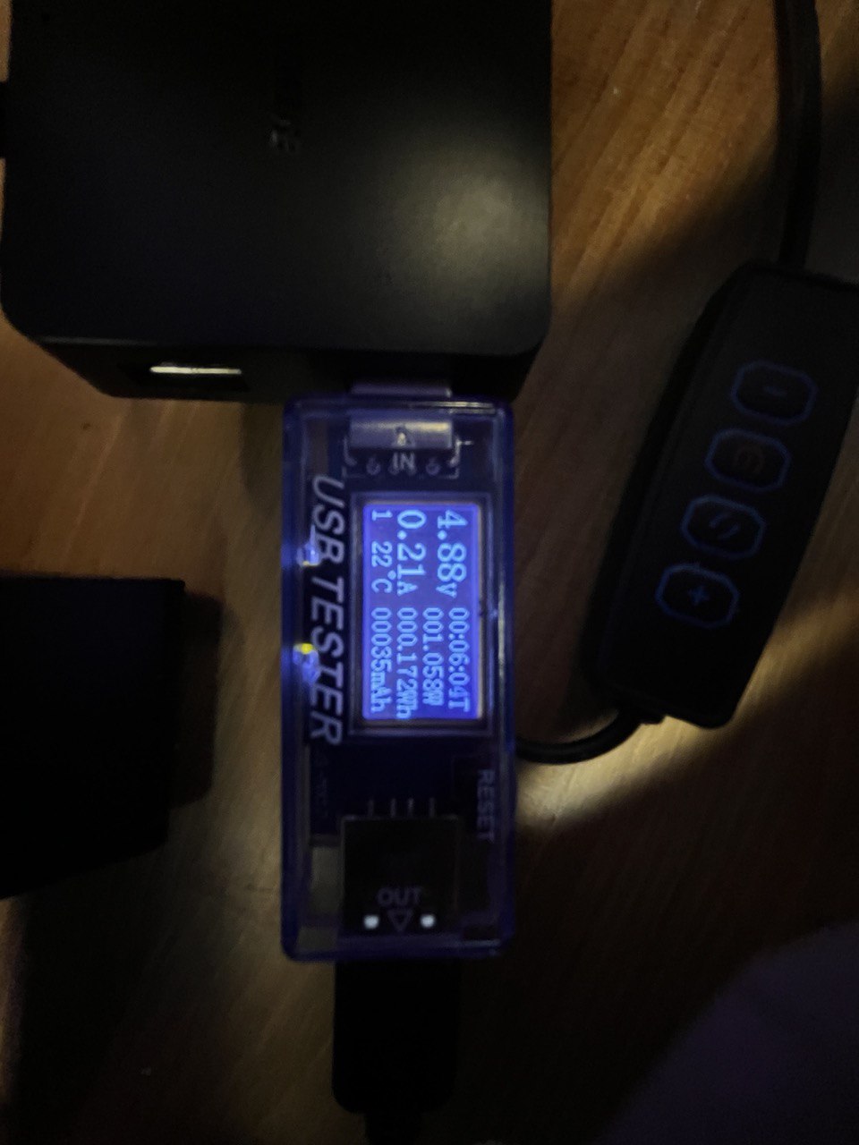
Here we can see the consumption of the servo motor at the time the video was taken, we can see how the consumption drops to zero when the motor is stopped and how it rises when its speed increases.
Summary
Specifications such as speed, torque, current and voltage are the determining elements in which motor is optimal for your project, although other requirements such as budget, size or complexity could also be taken into account. As each project is unique, one factor usually has more weight than the other in the decision-making process. By understanding what engines are available and developing a clear set of project parameters, you can avoid costly mistakes and select the best engine for the job.