1. Group assignment:
measure the power consumption of an output device.
2. Individual assignment:
add an output device to a microcontroller board you've designed, and program it to do something.
An Output Device is any piece of computer hardware that converts information or data into a human-perceptible form or, historically, into a physical machine-readable form for use with other non-computerized equipment. It can be text, graphics, tactile, audio, or video. Examples include monitors, printers, speakers, headphones, projectors, GPS devices, optical mark readers, and braille readers.
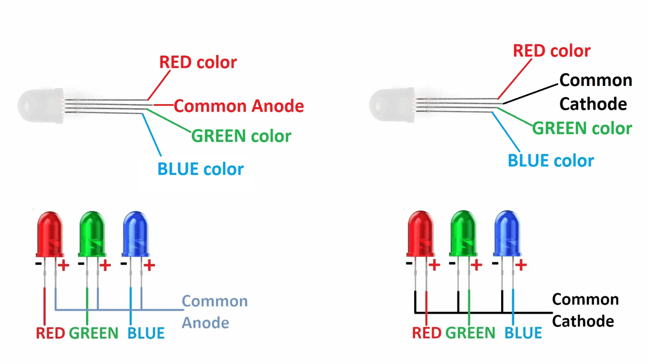
LEDs is a output device which offer high energy efficiency, converting a larger portion of electrical energy into light and making them the preferred choice for various lighting and display applications.
The RGB LED can produce any color,
An RGB LED is a combination of 3 LEDs in just one package:
We can produce almost any color by combining those three colors. An RGB LED is shown in the following Image:
#_Programming the RGB LED... :)
Code:
    #define RED_LED_PIN 7

#define GREEN_LED_PIN 8

#define BLUE_LED_PIN 9


void setup() {

  // Configure LED pins as outputs

  pinMode(RED_LED_PIN, OUTPUT);

  pinMode(GREEN_LED_PIN, OUTPUT);

  pinMode(BLUE_LED_PIN, OUTPUT);


  // Set common anode pin high for common anode LED

  digitalWrite(RED_LED_PIN, HIGH);

}


void loop() {

  // Set different colors (LED on = LOW, LED off = HIGH for common anode)

  digitalWrite(GREEN_LED_PIN, LOW);  // Turn green on

  digitalWrite(RED_LED_PIN, LOW);   // Turn red on

  digitalWrite(BLUE_LED_PIN, HIGH);  // Turn blue off

  delay(1000);


  digitalWrite(GREEN_LED_PIN, HIGH); // Turn green off

  digitalWrite(RED_LED_PIN, HIGH);   // Turn red off

  digitalWrite(BLUE_LED_PIN, LOW);   // Turn blue on

  delay(1000);

}
#_Code_Explanation... :)
#define RED_LED_PIN 7
#define GREEN_LED_PIN 8
#define BLUE_LED_PIN 9
These lines define nicknames (7, 8, and 9) for the physical pins connected to the red, green, and blue LEDs.
pinMode(RED_LED_PIN, OUTPUT);
pinMode(GREEN_LED_PIN, OUTPUT);
pinMode(BLUE_LED_PIN, OUTPUT);
This part sets up the LED pins. It tells the microcontroller to control these pins (like switches) to turn the LEDs on or off.
// Set common anode pin high for common anode LED
digitalWrite(RED_LED_PIN, HIGH);
(Optional for common anode LEDs) This line initially turns off the red LED by setting its pin to HIGH (might seem counterintuitive but it blocks the current flow).
void loop() {
// Set different colors (LED on = LOW, LED off = HIGH for common anode)
digitalWrite(GREEN_LED_PIN, LOW); // Turn green on
digitalWrite(RED_LED_PIN, LOW); // Turn red on
digitalWrite(BLUE_LED_PIN, HIGH); // Turn blue off
delay(1000);
digitalWrite(GREEN_LED_PIN, HIGH); // Turn green off
digitalWrite(RED_LED_PIN, HIGH); // Turn red off
digitalWrite(BLUE_LED_PIN, LOW); // Turn blue on
delay(1000);
}
This loop runs forever, blinking the LEDs:
It turns the green and red LEDs on (by setting their pins to LOW).
It turns the blue LED off (by setting its pin to HIGH).
It pauses for 1 second.
Then it turns the green and red LEDs off, and the blue LED on.
It pauses for another 1 second, creating a blinking effect.
#_Output... :)
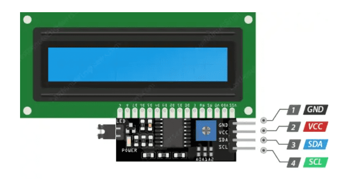
A liquid-crystal display (LCD) is a flat-panel display which uses the liquid crystals for giving the output. A 16x2 LCD display is very basic module and is very commonly used in various devices and circuits.
How LCDs works?
A display is made up of millions of pixels. The quality of a display commonly refers to the number of pixels; for example, a 4K display is made up of 3840 x2160 or 4096x2160 pixels. A pixel is made up of three subpixels; a red, blue and green—commonly called RGB. When the subpixels in a pixel change color combinations, a different color can be produced. With all the pixels on a display working together, the display can make millions of different colors. When the pixels are rapidly switched on and off, a picture is created.
The way a pixel is controlled is different in each type of display; CRT, LED, LCD and newer types of displays all control pixels differently. In short, LCDs are lit by a backlight, and pixels are switched on and off electronically while using liquid crystals to rotate polarized light. A polarizing glass filter is placed in front and behind all the pixels, the front filter is placed at 90 degrees. In between both filters are the liquid crystals, which can be electronically switched on and off.
LCDs are made with either a passive matrix or an active matrix display grid. The active matrix LCD is also known as a thin film transistor (TFT) display. The passive matrix LCD has a grid of conductors with pixels located at each intersection in the grid. A current is sent across two conductors on the grid to control the light for any pixel. An active matrix has a transistor located at each pixel intersection, requiring less current to control the luminance of a pixel. For this reason, the current in an active matrix display can be switched on and off more frequently, improving the screen refresh time.
Some passive matrix LCD's have dual scanning, meaning that they scan the grid twice with current in the same time that it took for one scan in the original technology. However, active matrix is still a superior technology out of the two.
Types of LCDs include:
1. Twisted Nematic (TN)- which are inexpensive while having high response times. However, TN displays have low contrast ratios, viewing angles and color contrasts.
2. In Panel Switching displays (IPS Panels)- which boast much better contrast ratios, viewing angles and color contrast when compared to TN LCDs.
3. Vertical Alignment Panels (VA Panels)- which are seen as a medium quality between TN and IPS displays.
4. Advanced Fringe Field Switching (AFFS)- which is a top performer compared IPS displays in color reproduction range.
#_Programming the I2C LCD... :)
1. Connections of I2C LCD Display to an Xiao ESP32 C3
ESP32C3 --> I2C LCD
SDA --> SDA
SCL --> SCL
3.3V --> 3.3V
GND --> GND
2. Adjusting The LCD Contrast
On the I2C module you will find a potentiometer that you can rotate with a small screwdriver to Adjust the contrast of the display.
3.Library Installation
To drive an I2C LCD you must first install a library called LiquidCrystal_I2C
To install the library go to Sketch --> Include Libraries --> Manage Libraries. Wait for Library Manager to download the library index and update the list of installed libraries.
Filter your search by typing ‘liquidcrystal‘. There should be some entries. Look for the LiquidCrystal I2C library by Marco Schwartz. Click on that entry, and then select Install.
4. Determining the I2C Address
The I2C address of your LCD depends on the manufacturer, as mentioned earlier. If your LCD has a Texas Instruments’ PCF8574 chip, its default I2C address is 0x27Hex. If your LCD has NXP Semiconductors’ PCF8574 chip, its default I2C address is 0x3FHex.
So your LCD probably has I2C address 0x27Hex or 0x3FHex. However it is recommended that you find out the actual I2C address of the LCD before using it. Luckily there’s an easy way to do this. Below is a simple I2C scanner sketch that scans your I2C bus and returns the address of each I2C device it finds.
Code:
        #include < LiquidCrystal_I2C.h >


            LiquidCrystal_I2C lcd(0x3F,16,2);  // set the LCD address to 0x3F for a 16 chars and 2 line display


            void setup() {

              lcd.init();

              lcd.clear();

              lcd.backlight();      // Make sure backlight is on


              // Print a message on both lines of the LCD.

              lcd.setCursor(2,0);   //Set cursor to character 2 on line 0

              lcd.print("SANJIVANI FAB LAB");


              lcd.setCursor(2,1);   //Move cursor to character 2 on line 1

              lcd.print("AKASH MHAIS");

            }


            void loop() {

            }
#_Code_Explanation... :)
#include < LiquidCrystal_I2C.h >
#include < LiquidCrystal_I2C.h >: This line includes the LiquidCrystal_I2C.h library, which provides functions for interacting with the LCD display.
LiquidCrystal_I2C lcd(0x3F,16,2); // set the LCD address to 0x3F for a 16 chars and 2 line display
LiquidCrystal_I2C lcd(0x3F, 16, 2);: This line creates an object called lcd of the LiquidCrystal_I2C class. It defines the following:
0x3F: The I2C address of the LCD (this might need to be adjusted based on your specific LCD model). You can find the I2C address by using an I2C scanner sketch.
16: The number of characters per line on the LCD (16 characters in this case).
2: The number of lines on the LCD (2 lines in this case).
(setup function):
void setup() { ... }: This block defines the setup function which runs only once when the program starts.
lcd.init();: Initializes the communication with the LCD.
lcd.clear();: Clears any existing text on the LCD.
lcd.backlight();: Turns on the LCD backlight (optional but useful for viewing the display).
lcd.setCursor(2, 0);: Sets the cursor position to the 2nd character (0-based indexing) on the first line (line 0).
lcd.print("SANJIVANI FAB LAB");: Prints the message "SANJIVANI FAB LAB" on the first line.
lcd.setCursor(2, 1);: Sets the cursor position to the 2nd character on the second line (line 1).
lcd.print("AKASH MHAIS");: Prints the message "AKASH MHAIS" on the second line.
(loop function):
void loop() { ... }: This block defines the loop function which runs repeatedly after the setup function finishes.
//: The double forward slashes indicate a comment. This specific line is a comment and has no effect on the code's functionality. Since the loop function is empty, the program will display the message set in setup and won't update it further.
After uploading the code, open the serial monitor at a baud rate of 115200 and press the EN button on the ESP32. You will see the I2C address of your I2C LCD display.
Tutorial reference --> Last Minute Engineers
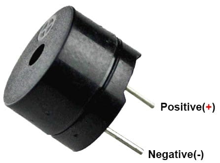
A buzzer or beeper which may be mechanical, electromechanical, or piezoelectric (piezo for short). it is an electronic signaling device that makes a buzzing sound.
1. Electromechanical:
The electric buzzer was invented in 1831 by Joseph Henry. They were mainly used in early doorbells until they were phased out in the early 1930s in favor of musical chimes, which had a softer tone.
Early devices were based on an electromechanical system identical to an electric bell without the metal gong. Similarly, a relay may be connected to interrupt its own actuating current, causing the contacts to buzz (the contacts buzz at line frequency if powered by alternating current) Often these units were anchored to a wall or ceiling to use it as a sounding board. The word "buzzer" comes from the rasping noise that electromechanical buzzers made.
2. Piezoelectric:
Piezoelectric buzzers, or piezo buzzers, as they are sometimes called, were invented by Japanese manufacturers and fitted into a wide array of products during the 1970s to 1980s. This advancement mainly came about because of cooperative efforts by Japanese manufacturing companies. In 1951, they established the Barium Titanate Application Research Committee, which allowed the companies to be "competitively cooperative" and bring about several piezoelectric innovations and inventions.
A piezoelectric element may be driven by an oscillating electronic circuit or other audio signal source, driven with a piezoelectric audio amplifier. Sounds commonly used to indicate that a button has been pressed are a click, a ring or a beep.
Interior of a readymade loudspeaker, showing a piezoelectric-disk-beeper (With 3 electrodes ... including 1 feedback-electrode ( the central, small electrode joined with red wire in this photo), and an oscillator to self-drive the buzzer.
A piezoelectric buzzer/beeper also depends on acoustic cavity resonance or Helmholtz resonance to produce an audible beep.
#_Programming the Buzzer... :)
    #define buzzerPin 0  //  (any digital pin)


void setup() {

  // Configure the buzzer pin as output

  pinMode(buzzerPin, OUTPUT);

}


void loop() {

  // Play a simple tone

  tone(buzzerPin, 1000);  // 1 kHz Frequency

  delay(250);           //  250 milliseconds Duration


  // play a silent period

  noTone(buzzerPin);

  delay(250);           //  250 milliseconds Duration of silence

}
#_Code_Explanation... :)
#define buzzerPin 0 // (any digital pin): This line defines a constant named buzzerPin with a value of 0. This represents the digital pin on the Arduino that the buzzer is connected to. You can change this value (0) to the actual pin number you're using.
(setup function):
void setup() { ... }: This block defines the setup function which runs only once when the program starts.
pinMode(buzzerPin, OUTPUT);: Sets the pin defined by buzzerPin (pin 0 in this case) as an output pin. This tells the Arduino that this pin can be used to control external devices like the buzzer.
(loop function):
void loop() { ... }: This block defines the loop function which runs repeatedly after the setup function finishes. This loop creates the beeping sound.
tone(buzzerPin, 1000); // 1 kHz Frequency: This line uses the tone function to generate a sound on the buzzerPin. It provides two arguments:
buzzerPin: The pin where the buzzer is connected (defined earlier as buzzerPin).
1000: The frequency of the sound in Hertz (Hz). Here, 1000 Hz translates to a sound with 1000 cycles per second, which is perceived as a 1 kHz tone.
delay(250); // 250 milliseconds Duration: This line pauses the program for 250 milliseconds (quarter of a second). This creates the duration of the beep.
noTone(buzzerPin);: This line stops the sound generation on the buzzerPin.
delay(250); // 250 milliseconds Duration of silence: This line pauses the program for another 250 milliseconds, creating a silent period between beeps.
#_PCB_Designing_in_Eagle_:)
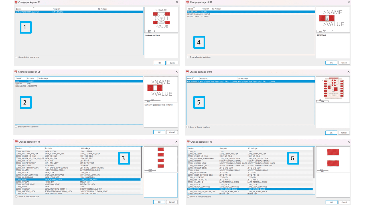
I will going to use a 2 pin connector, 4 pin connector, push button, LED and Resistor, these are the Schematic symbol of all the components.
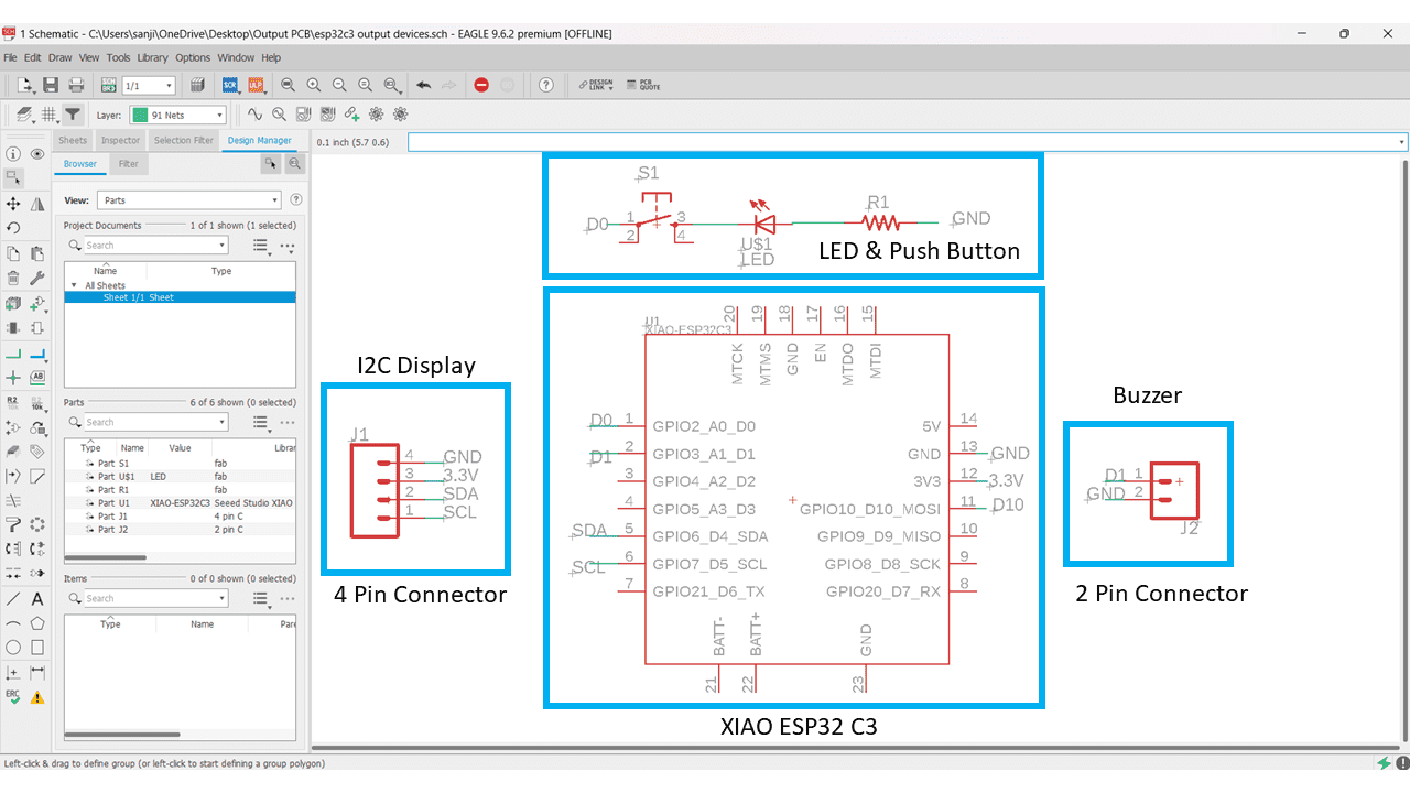
This is the Schematic of my output devices board
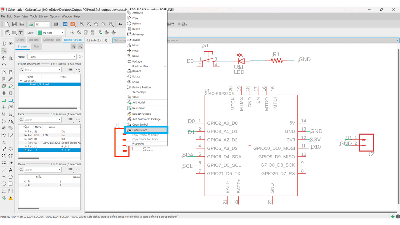
I used the Connectors from Sparkfun Library but they are very small so i just changed the footprints by editing the library. for that select the symbol --> right click on it --> navigate to open device.
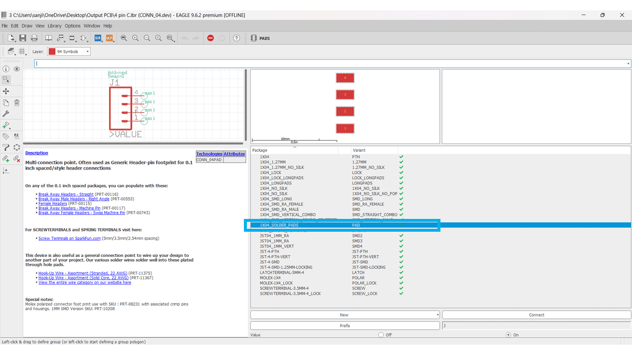
Select the footprint which we have to edit.
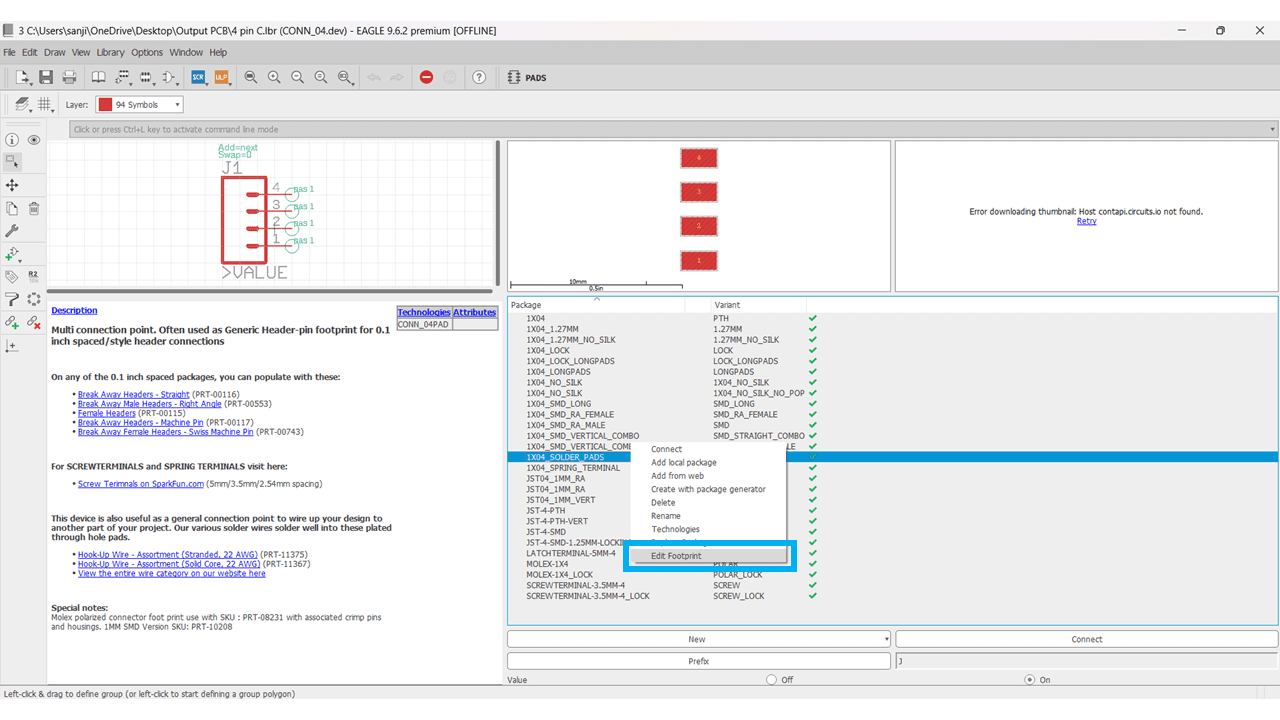
By right clicking on that select edit footprint option.
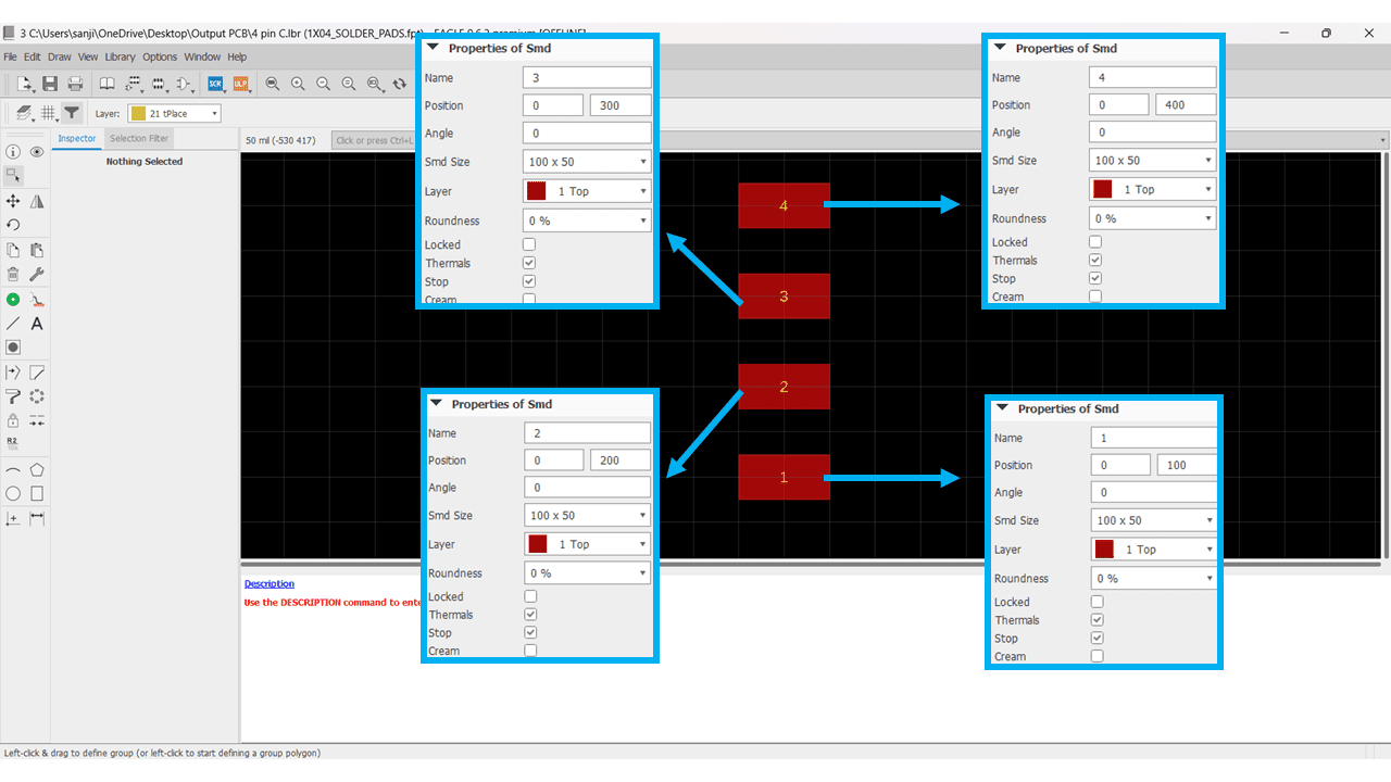
I changed the footprints settings according to the connectors that I have available in our fab lab.
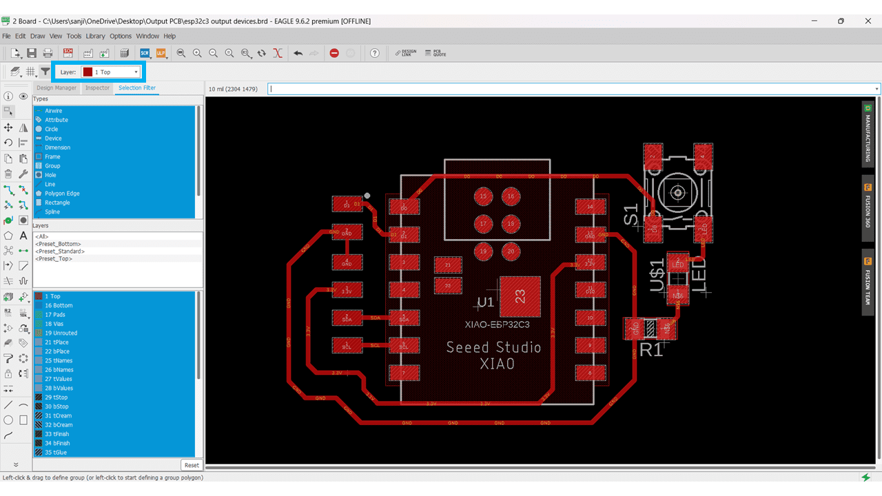
I have designed the board by setting the trace width 16 mils.
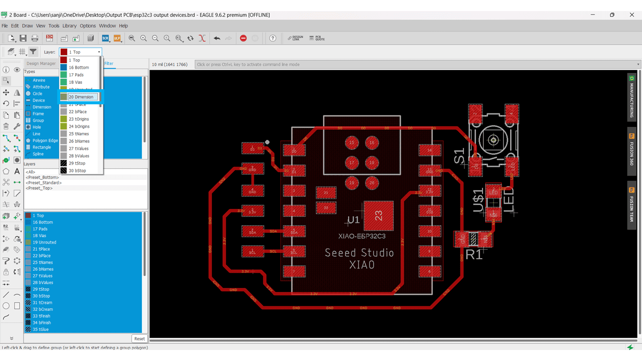
after the design of all the traces i navigated to the dimension layer option.
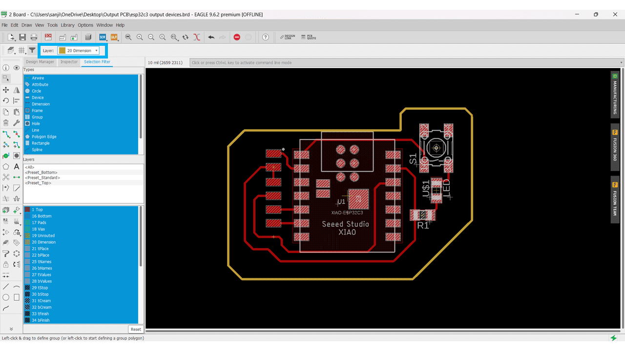
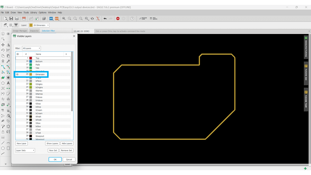
I drawn the outline for the board.
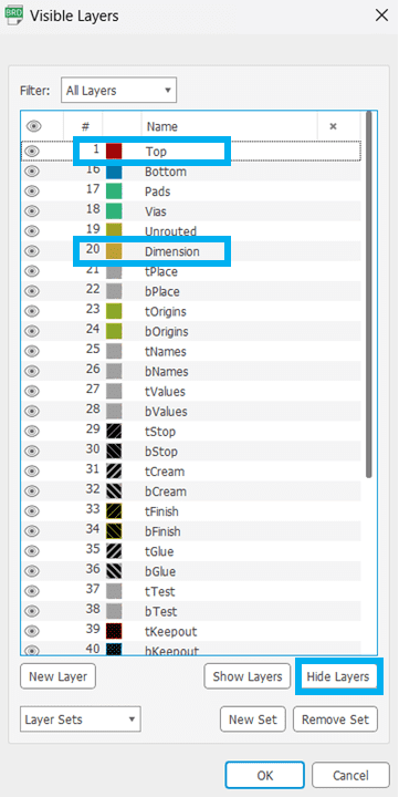
Then I go to layers and selected the Hide Layers option, for this pcb only top layer and the dimension layer is required.
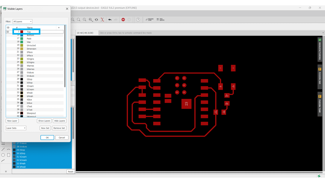
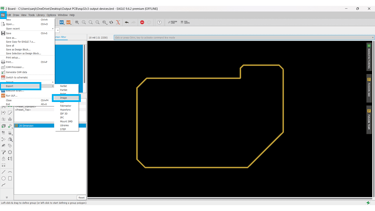
I selected the Top layer for converting it into png format.
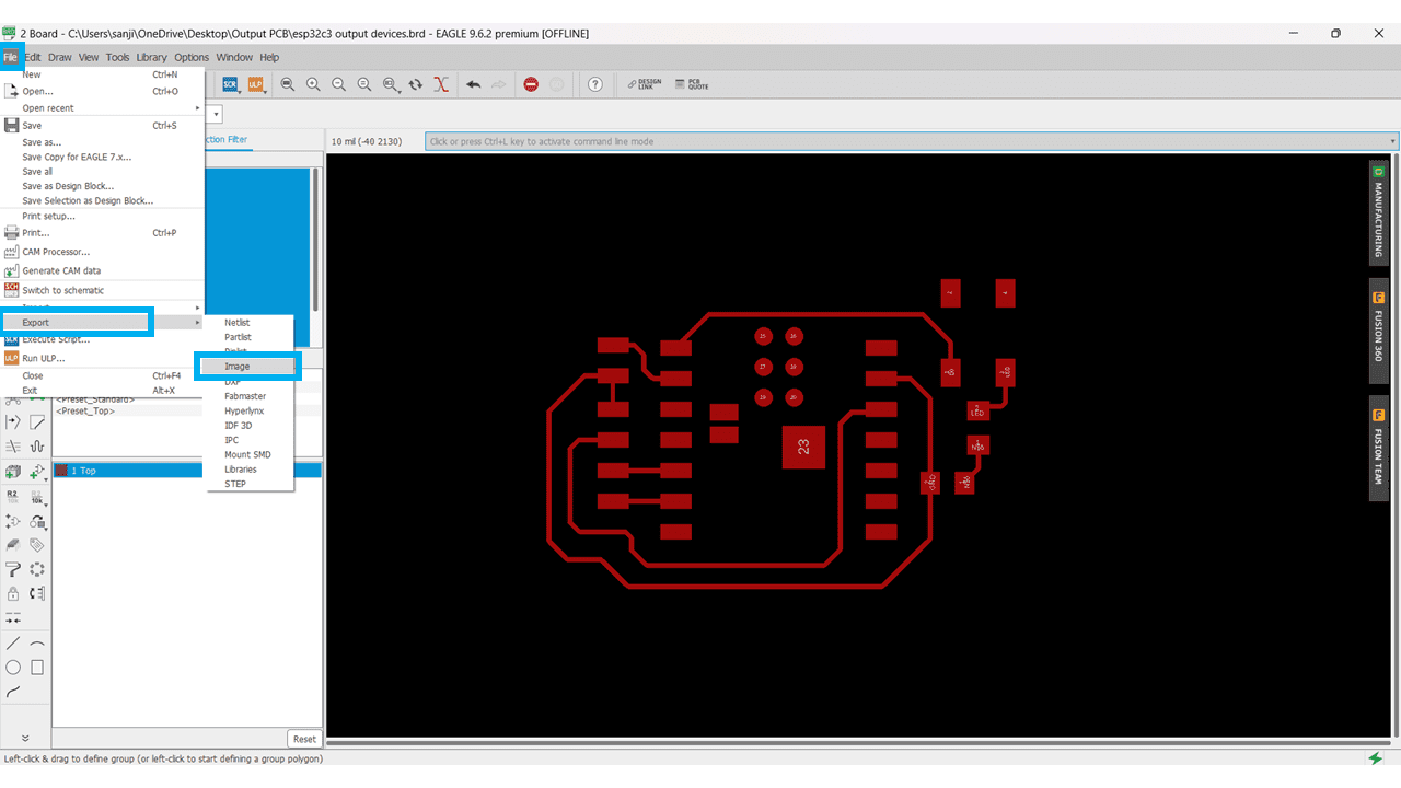
For converting it go to File --> Export --> Image.
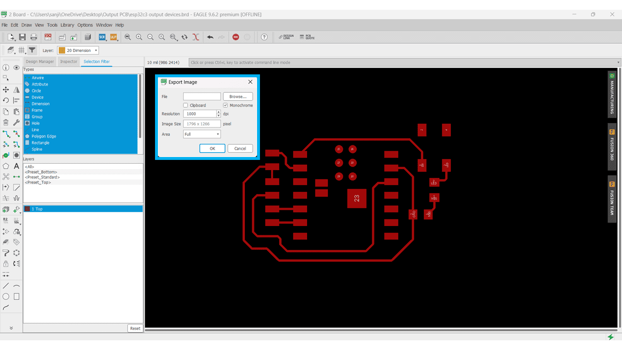
the Export Image window will popup, Select Monochrome option and 1000 pixel resolution for the fine quality.
For the outline again select the dimension layer and hide remaining all layers.
For converting it into .png format, go to File --> Export --> Image.
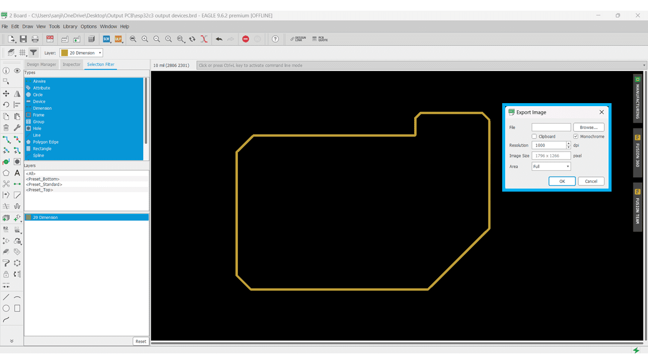
the Export Image window will popup, Select Monochrome option and 1000 pixel resolution for the fine quality.
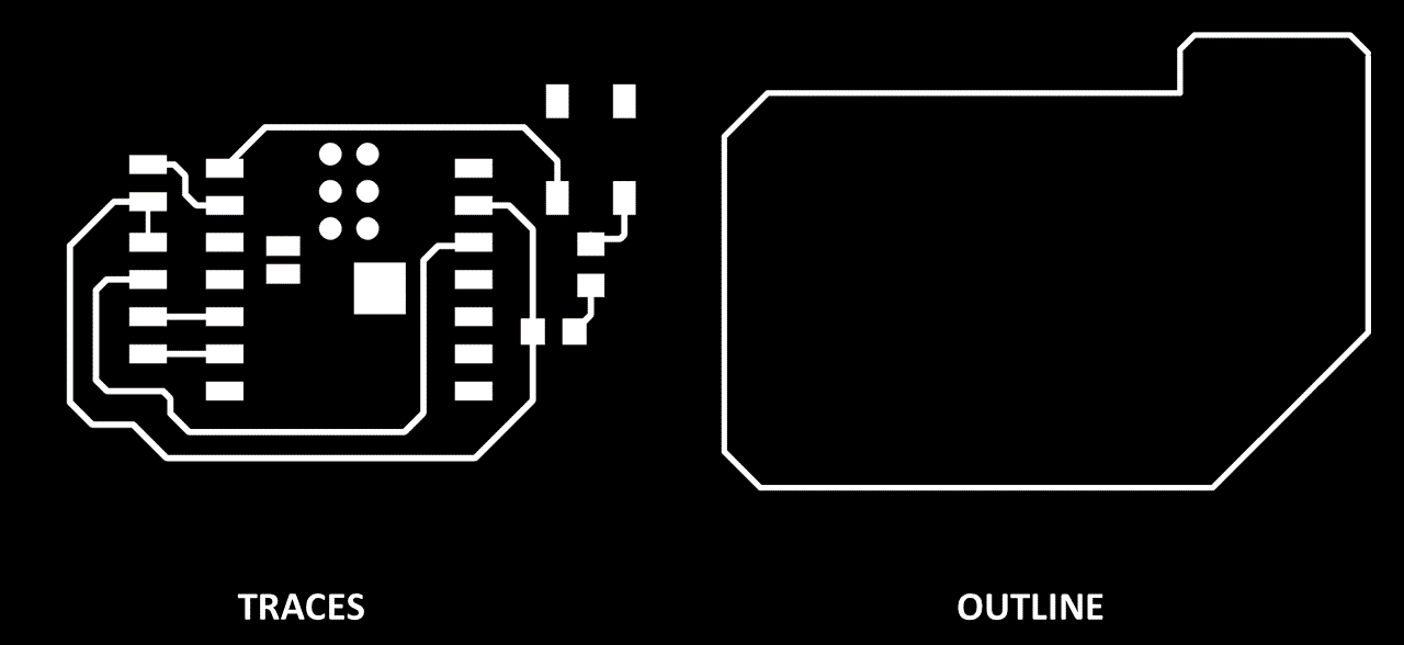
This is the output of the PCB designing in Eagle software.
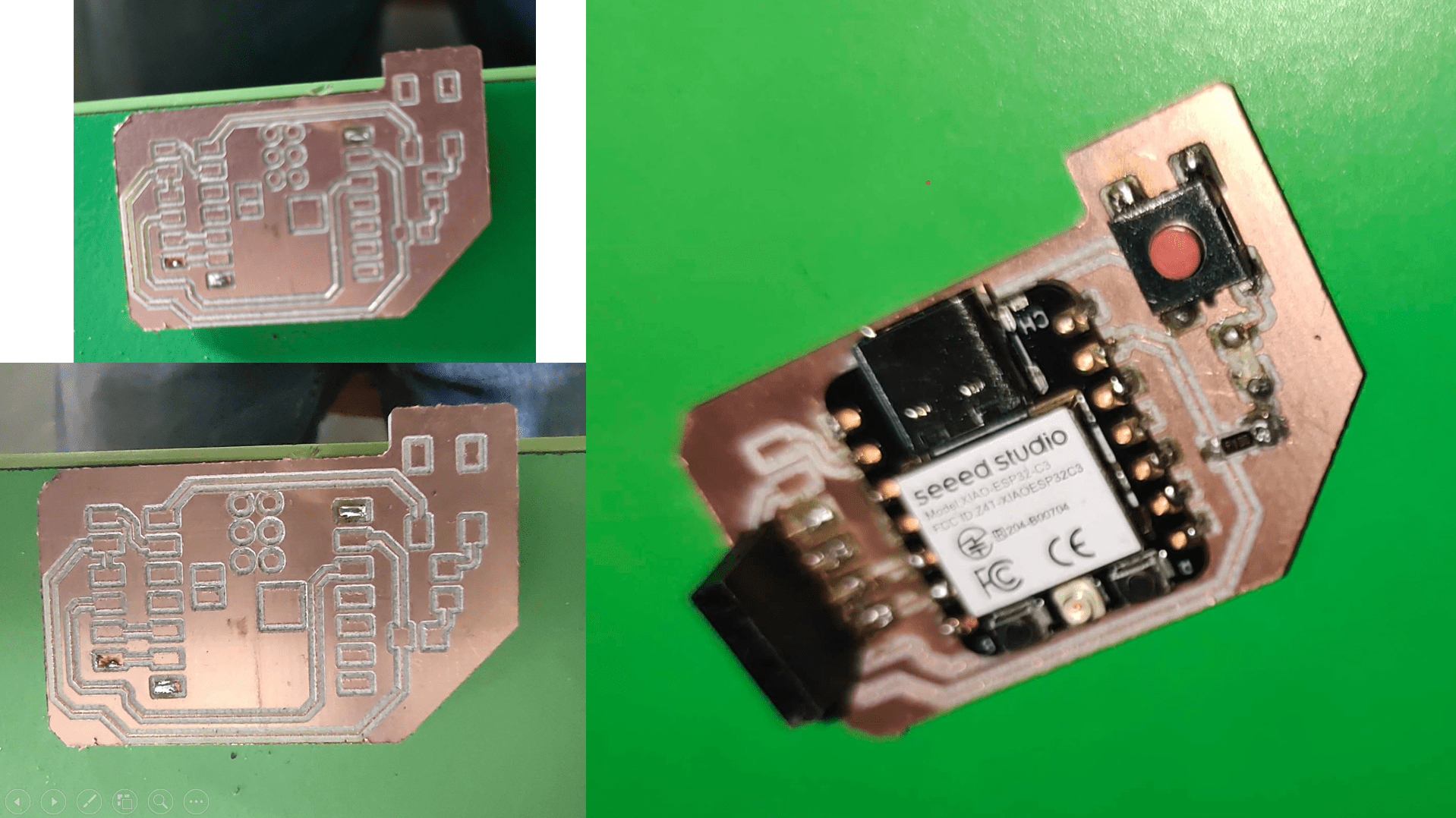
I mill this on PCB milling machine and then i soldered it
This code essentially turns on the LED connected to pin D0 for 1 second, then pauses for another second, and repeats this process continuously. This creates a blinking effect with the LED turning on and off every other second.
#_Code_for_LED_Blink_:)
void setup() {

    // initialize digital pin LED_BUILTIN as an output.

    pinMode(D0, OUTPUT);

  }


  // the loop function runs over and over again forever

  void loop() {

    digitalWrite(D0, HIGH);  // turn the LED on (HIGH is the voltage level)

    delay(1000);                      // wait for a second


  }
#_Code_Explanation... :)
(setup function):
void setup() defines a function that runs once when you power up the Arduino or press the reset button.
pinMode(D0, OUTPUT); sets the digital pin D0 (pin number 0) as an output. This tells the Arduino that this pin can be used to control external devices like LEDs.
(loop function):
void loop() defines another function that runs repeatedly forever, creating a continuous loop.
digitalWrite(D0, HIGH); turns on the LED connected to pin D0. In Arduino, HIGH typically corresponds to a higher voltage level (around 5V), which activates the LED.
delay(1000); pauses the program for 1 second (1000 milliseconds). This creates a delay between turning the LED on and off.
#_Output... :)
This code displays "Hello, World!" on both lines of the LCD for 1 second each, then clears the display and repeats the process. You can modify the messages, cursor positions, and delays within the loop function to create different displays.
#_Code_for_I2C_LCD_:)
        #include < LiquidCrystal_I2C.h >


            // set the LCD number of columns and rows

            int lcdColumns = 16;

            int lcdRows = 2;


            // set LCD address, number of columns and rows

            // if you don't know your display address, run an I2C scanner sketch

            LiquidCrystal_I2C lcd(0x27, lcdColumns, lcdRows);


            void setup(){

              // initialize LCD

              lcd.init();

              // turn on LCD backlight

              lcd.backlight();

            }


            void loop(){

              // set cursor to first column, first row

              lcd.setCursor(0, 0);

              // print message

              lcd.print("Hello, World!");

              delay(1000);

              // clears the display to print new message

              lcd.clear();

              // set cursor to first column, second row

              lcd.setCursor(0,1);

              lcd.print("Hello, World!");

              delay(1000);

              lcd.clear();

            }
#_Code_Explanation... :)
#include < LiquidCrystal_I2C.h >
#include is a preprocessor directive that tells the compiler to include another file. The specific file name is likely missing, but it's probably the LiquidCrystal_I2C.h library which provides functions to control the LCD.
int lcdColumns = 16;
int lcdRows = 2;
These lines define two integer variables:
lcdColumns: Stores the number of characters per line on the LCD (set to 16 in this case).
lcdRows: Stores the number of lines on the LCD (set to 2 in this case).
LiquidCrystal_I2C lcd(0x27, lcdColumns, lcdRows);
This line creates an object called lcd of the LiquidCrystal_I2C class. It defines:
The I2C address of the LCD (likely 0x27 in this case). You might need to adjust this value based on your specific LCD model.
The number of characters per line (set from the lcdColumns variable).
The number of lines (set from the lcdRows variable).
(setup function):
setup runs once when the program starts.
lcd.init(): Initializes the LCD communication.
lcd.backlight(): Turns on the LCD backlight (optional but useful to see the display).
(loop function):
loop runs repeatedly after setup.
lcd.setCursor(0, 0);: Sets the cursor position to the first character (0-based indexing) on the first line (line 0).
lcd.print("Hello, World!"): Prints the message "Hello, World!" on the first line.
delay(1000);: Pauses the program for 1 second (1000 milliseconds).
lcd.clear(): Clears any existing text on the LCD.
lcd.setCursor(0,1);: Sets the cursor position to the first character on the second line (line 1).
lcd.print("Hello, World!"): Prints the message "Hello, World!" on the second line.
delay(1000);: Pauses the program for another 1 second.
lcd.clear(): Clears the display again.
#_Output... :)