1. Group assignment:
measure the power consumption of an output device.
In Output Devices week, we explored various types of output devices and learned how to measure their power consumption.
1. Servo Motor:
A servomotor is a closed-loop servomechanism that uses position feedback (either linear or rotational position) to control its motion and final position. The input to its control is a signal (either analog or digital) representing the desired position of the output shaft.
        #include < ESP32Servo.h >


            Servo myservo;  // create servo object to control a servo


            int servoPin = 14;  // GPIO pin to which the servo is connected

            int pos = 0;    // variable to store the servo position


            void setup() {

              myservo.attach(servoPin);  // attaches the servo on GPIO 14 to the servo object

            }


            void loop() {

              for (pos = 0; pos <= 180; pos += 1) { // goes from 0 degrees to 180 degrees

                myservo.write(pos);              // tell servo to go to position in variable 'pos'

                delay(15);                       // waits 15ms for the servo to reach the position

              }

              for (pos = 180; pos >= 0; pos -= 1) { // goes from 180 degrees to 0 degrees

                myservo.write(pos);              // tell servo to go to position in variable 'pos'

                delay(15);                       // waits 15ms for the servo to reach the position

              }

            }
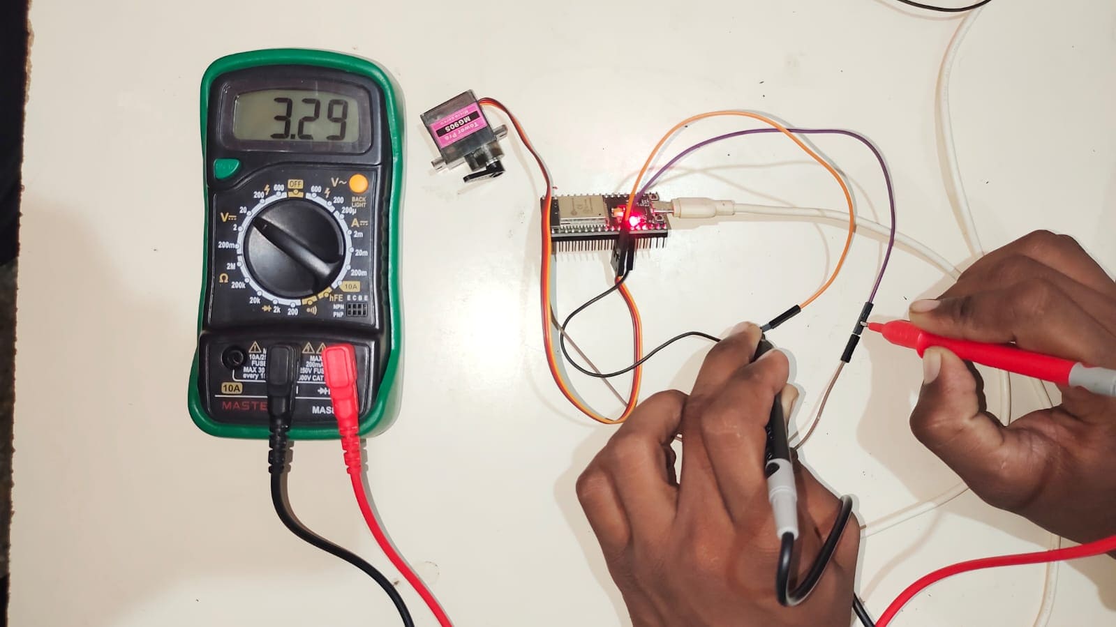
We Measured the Voltage of the Servo Motor by connecting the Multimeter parallel with the vcc and ground nodes of the Servo Motor, we got the multimeter reading as 3.29V
To measure the voltage of a servo motor using a multimeter, follow these steps:
Turn Off Power: Ensure the power to the servo motor is turned off before connecting the multimeter.
Set Multimeter: Set your multimeter to measure DC voltage. Choose a range that is higher than the expected voltage of the servo.
Connect Probes:
Positive Probe (Red): Connect the positive probe to the positive power lead or terminal of the servo motor.
Negative Probe (Black): Connect the negative probe to the negative power lead or terminal (usually ground).
Turn On Power: Turn the power back on to the servo motor while ensuring all connections are secure.
Read Voltage: Observe the reading on the multimeter display. This value is the voltage being supplied to the servo motor.
Turn Off Power: Once the measurement is complete, turn off the power before disconnecting the probes.
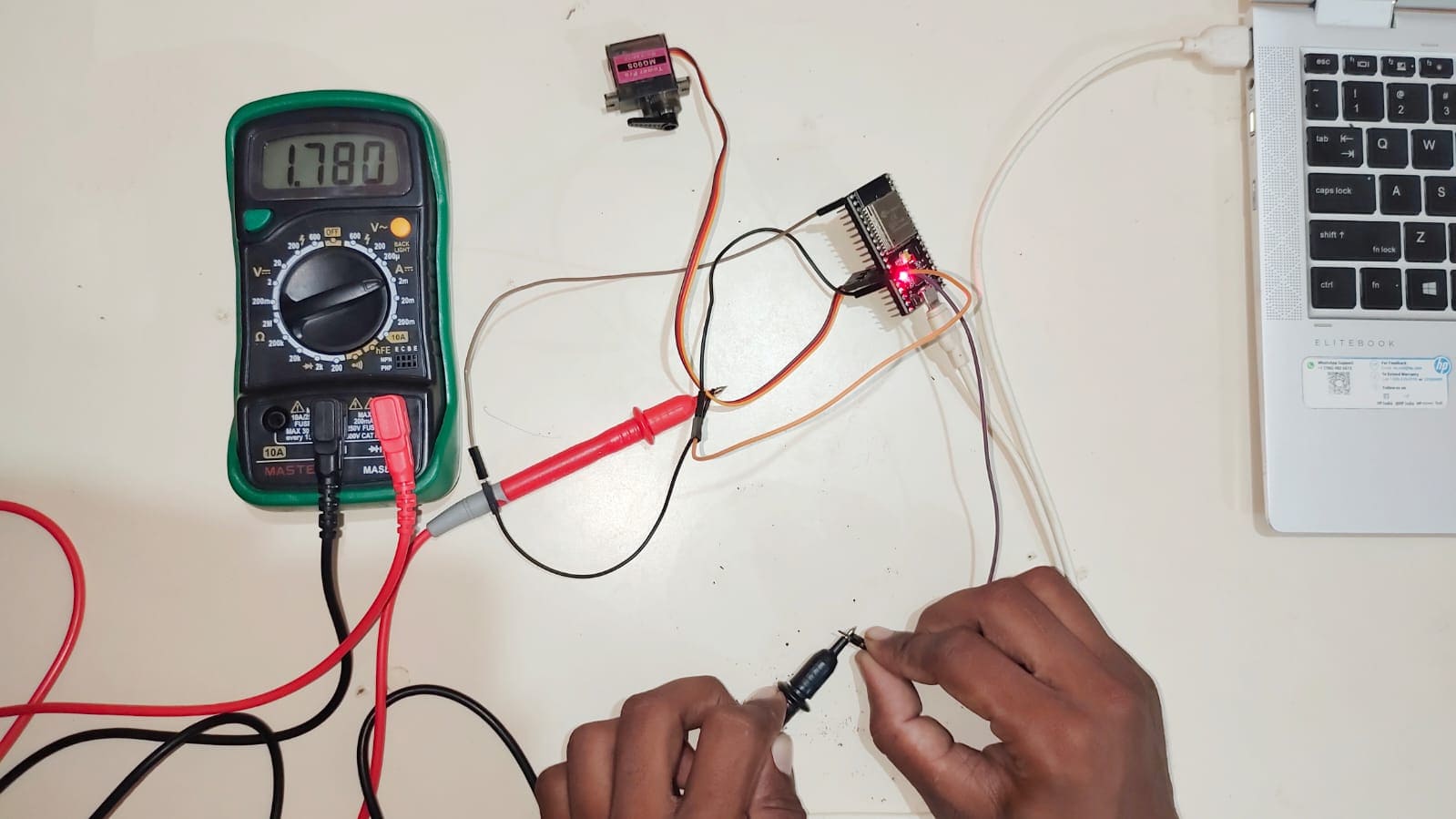
For Measurement of Current:
Connect Multimeter in Series:
Positive Probe (Red): Connect the positive probe of the multimeter to the positive terminal of the power supply.
Negative Probe (Black): Connect the negative probe of the multimeter to the positive lead of the servo motor.
We Measured the Current of 1.78 mA
Power Consumption(P):
P=V x I
P= 3.29 x (1.78/1000) = 0.00575 W.
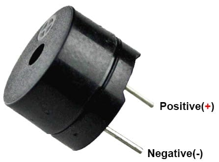
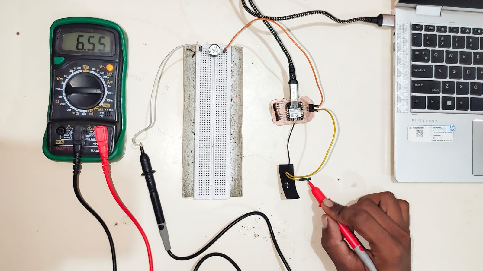
2. Buzzer:
A buzzer or beeper which may be mechanical, electromechanical, or piezoelectric (piezo for short). it is an electronic signaling device that makes a buzzing sound.
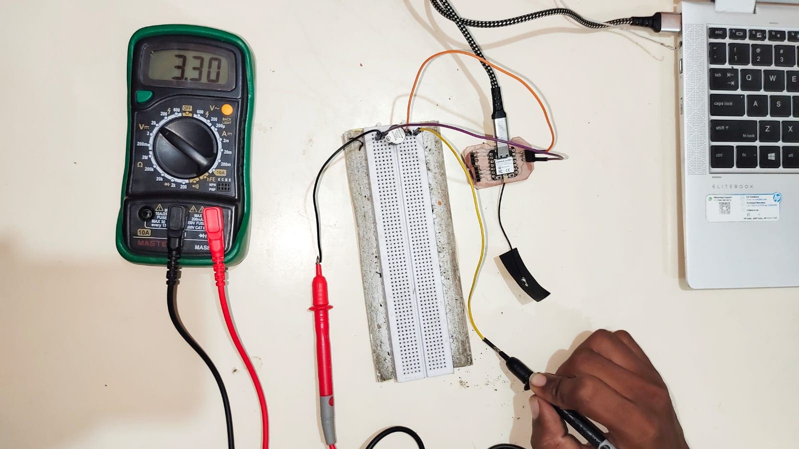
Voltage Measurement:
Turn Off Power.
Set Multimeter to DC voltage.
Connect Probes: Positive to positive, negative to negative.
Turn On Power and read the voltage.
Turn Off Power when done.
We Measured the Voltage of buzzer = 3.30V
Current Measurement:
Turn Off Power.
Set Multimeter to measure DC current (A).
Disconnect the Circuit: Break the positive connection to the buzzer.
Connect Multimeter in Series:
Positive probe to the power source.
Negative probe to the buzzer's positive terminal.
Turn On Power and read the current.
Turn Off Power and reconnect the circuit when done.
We Measured the Current of buzzer = 6.55mA
Power Consumption(P):
P=V x I
P= 3.30 x (6.55/1000) = 0.216 W.