This week, I will be using a computer-controlled machine to create an object using 12mm thick plywood. The object will have one parameter set to 1 meter, either its length, width, or height. Firstly, I will design the object using Solidworks, and then I will use Vcarve software to generate the " .cnc " file for the CNC router machine. Next, I will import that file into the machine's software and set all the parameters and coordinates. Finally, I will cut the object and assemble it.
-do your lab's safety training
-test runout, alignment, fixturing, speeds, feeds, materials,
and toolpaths for your machine
Visit our Group assignment page here.
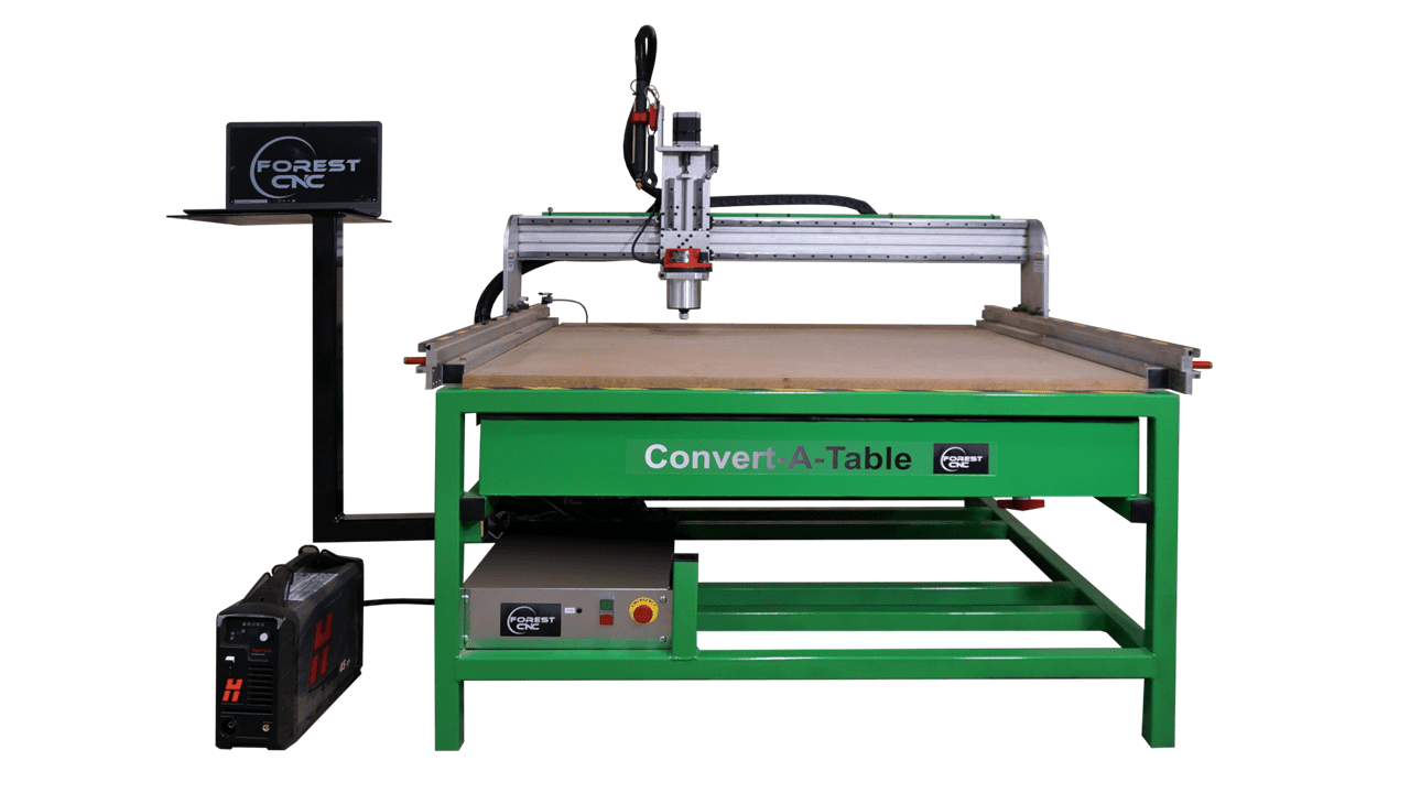
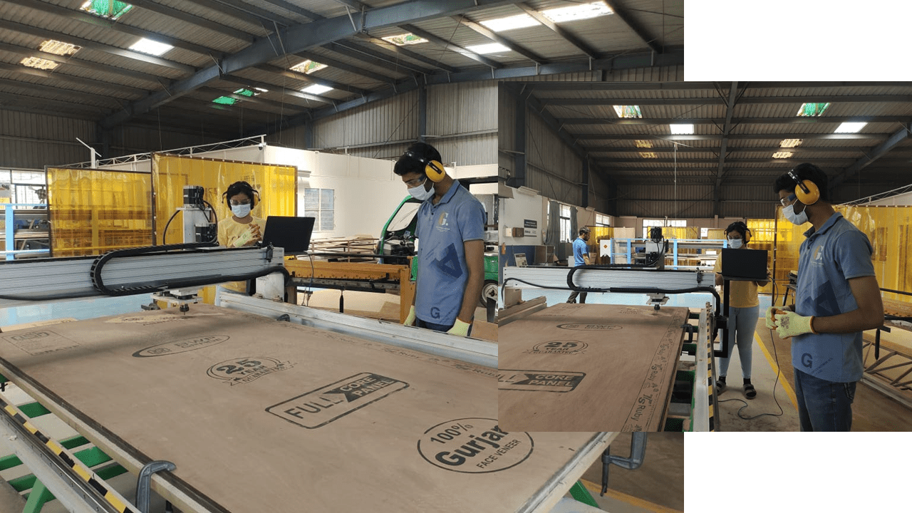
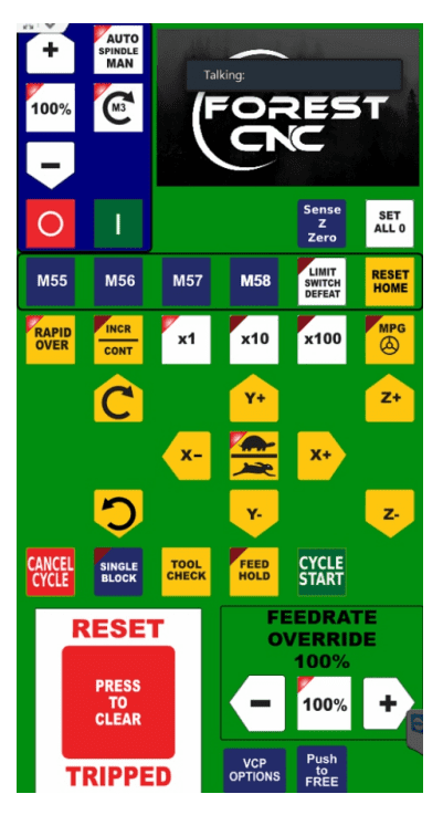
I utilized the CNC router machine manufactured by "FOREST CNC," which has a bed size of 8x4 feet and a maximum motor speed of 24000 rpm.
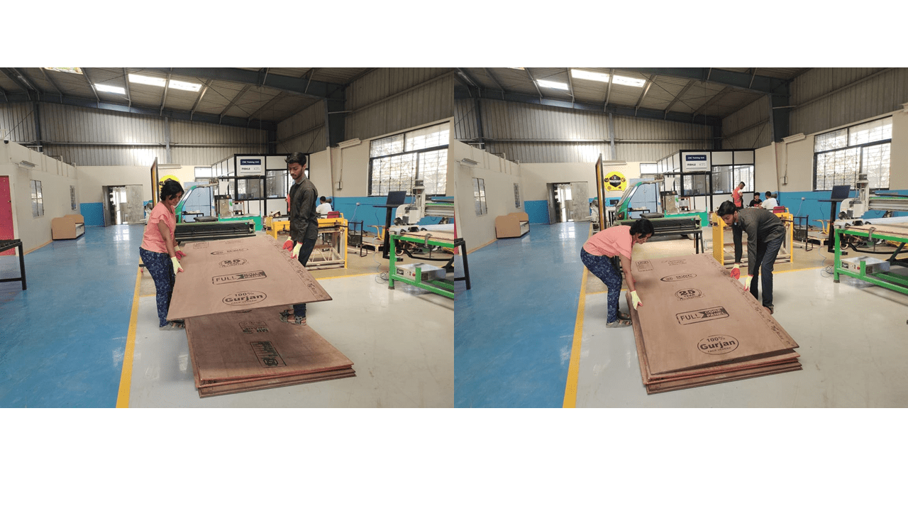
I used plywood measuring 2400mm in height and 1200mm in width, with a thickness of 12mm.
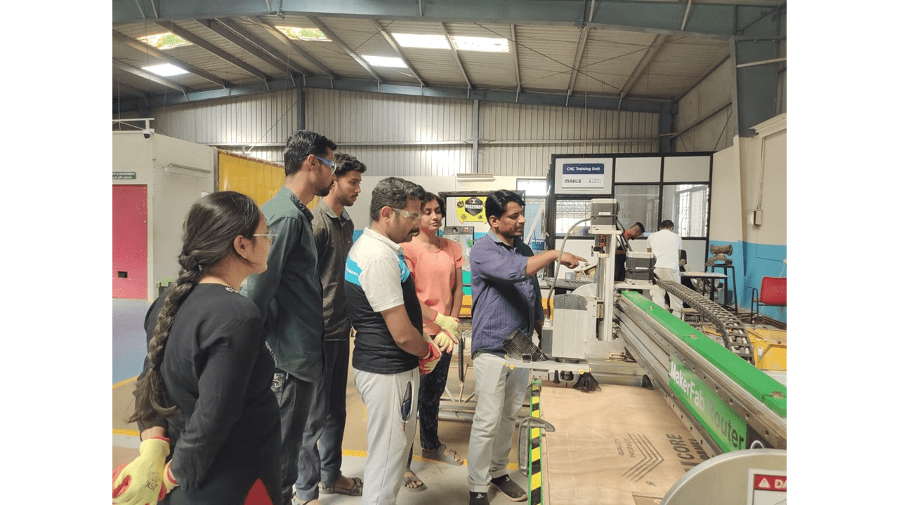
Our instructor, Suhas sir, conducted an orientation session about the machine. He explained how the machine operates and outlined the safety precautions we need to adhere to during our work. It was emphasized that one person should always stand near the emergency switch while the machine is in operation. Additionally, he provided an orientation on the software that we will be using for this assignment.
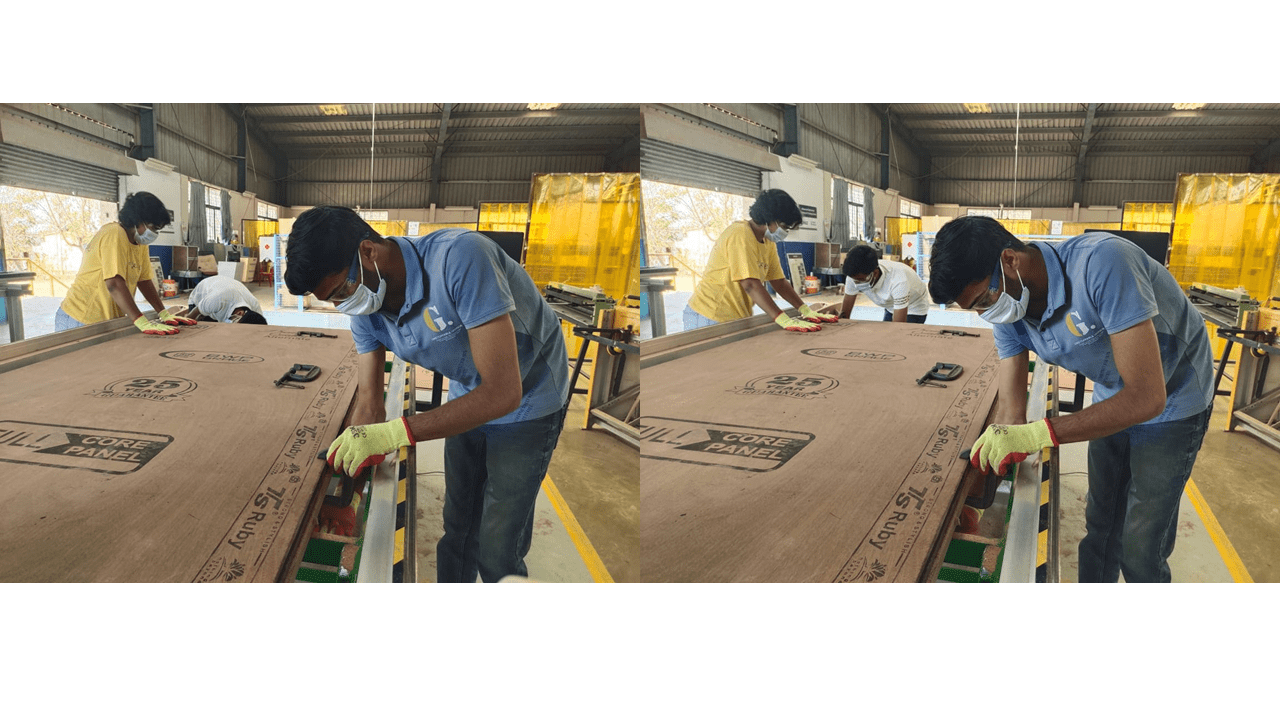
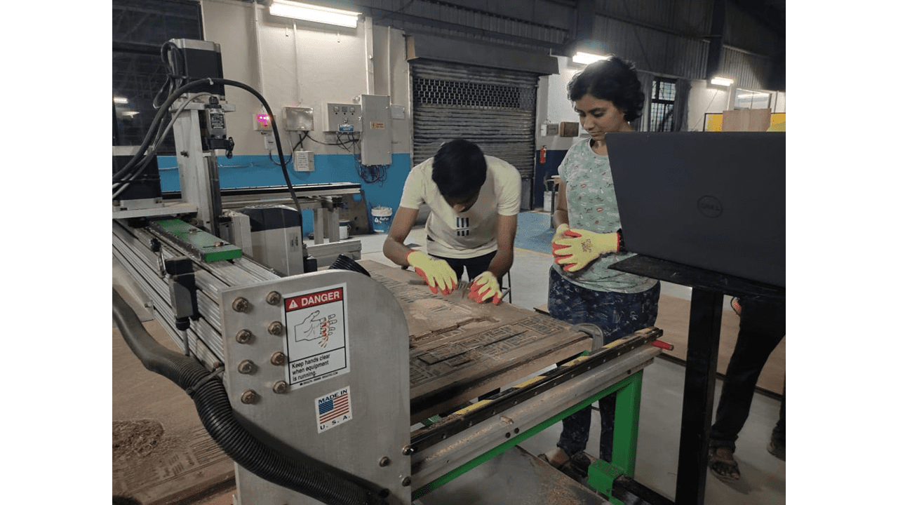
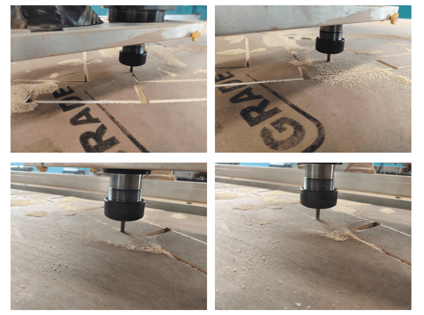
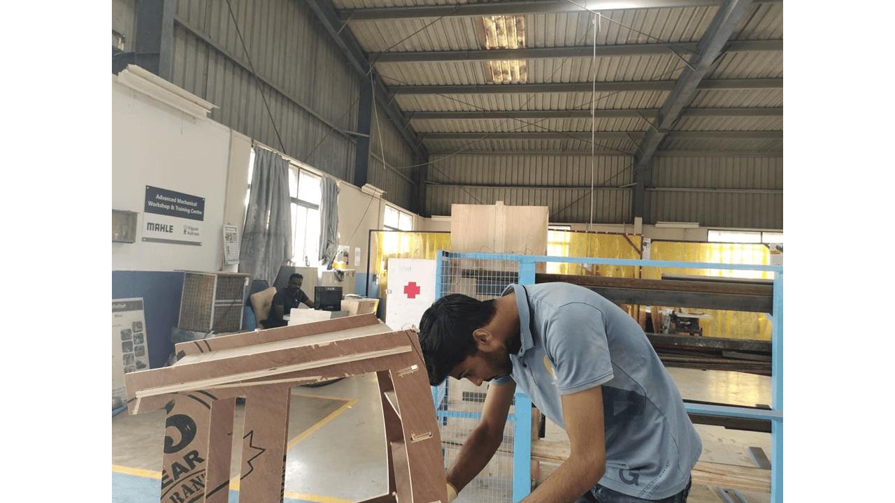
Then, I clamped the 12mm plywood securely onto the bed using C-clamps. It is crucial to properly fix the material in place; otherwise, accidents may occur, or the material could become dislodged. Therefore, ensuring the material is securely fixed is of utmost importance.
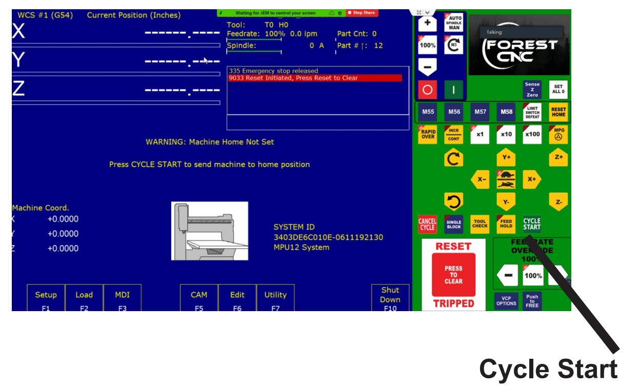
This is the interface of the machine's software in which on the right side we can control the machine and their X, Y, Z orientations and
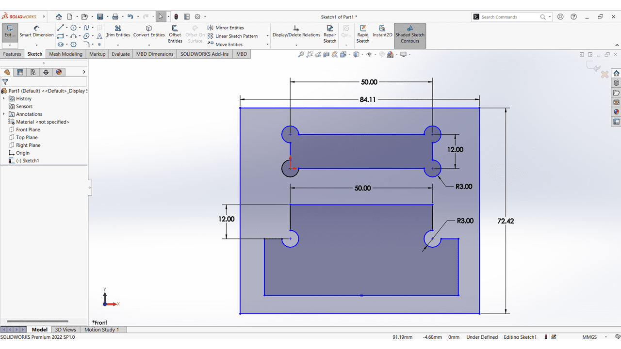
I designed the Dogbone Profile Slots as part of our group assignment for kerf calculations.
I refered theVCarvePro_Reference_Manual_V5_5 for getting used friendly with the software
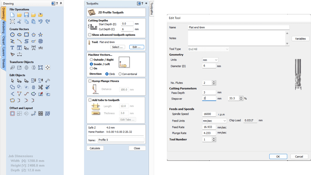
This is the toolpath I generated using the software. I imported a .dxf file and selected the toolpath option, which offers three choices: outside, inside, and on line. I opted for outside to cut the outer edges and inside for the closed slots. Afterward, I clicked on "save toolpath" and saved the file as a .cnc file, which is compatible with the Forest CNC machine software.
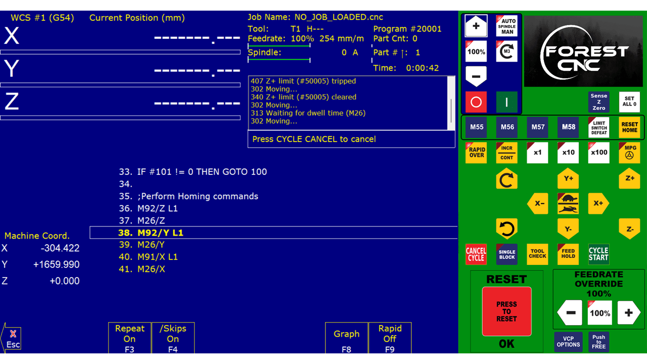
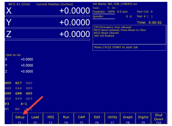
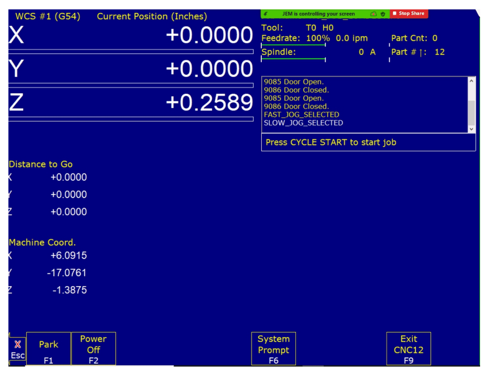
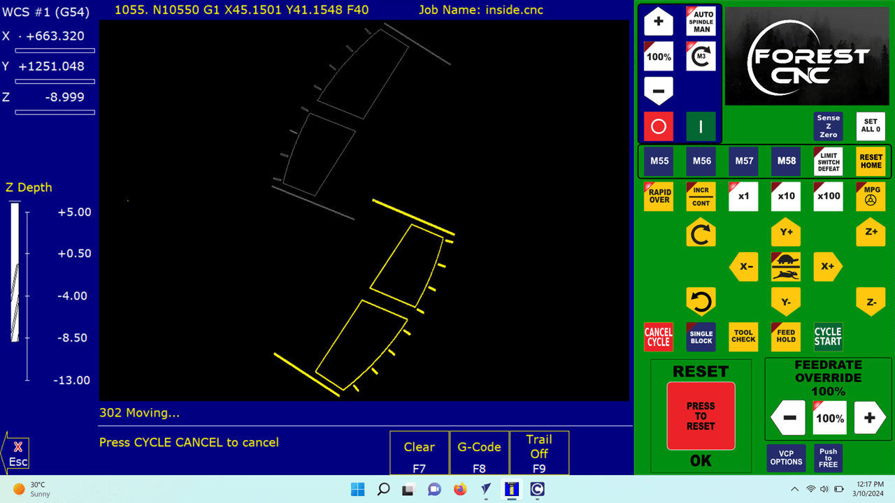
This is the interface of the machine's software. On the right side, we can control the machine's X, Y, Z orientations, and adjust the spindle speed and feed rate. To begin, we import the .cnc file using the "Load" option in the software's GUI. To visualize the toolpath, we click on the "Graph" option. After setting the origin using the software, we initiate the cutting process by clicking on "Start Cycle." Then, the machine begins cutting the object for which we created the toolpath.
After successfully cutting the dogbone profile, I measured the kerf. However, I didn't observe any kerf because I selected the "outside" parameter for the outer edges and "inside" parameter for the inside edges of the profile during toolpath generation. However, when I tested using the "on line" mode, the tool cut half the diameter of the tool inside the part. Consequently, I found that I had 3mm less on all sides because the tool diameter in my case is 6mm.
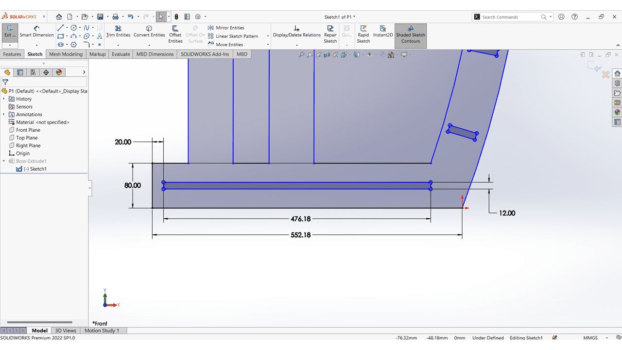
For my individual assignment, I designed the podium using SolidWorks. I utilized various commands such as the line command, circle command, arc, offset command, and constraints to create and fix the design.
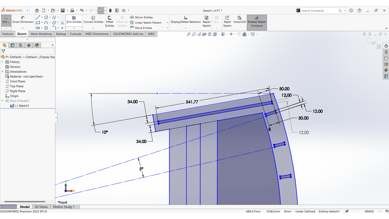
I've added an upper slot to the podium and smoothed out all the corners using the fillet command.
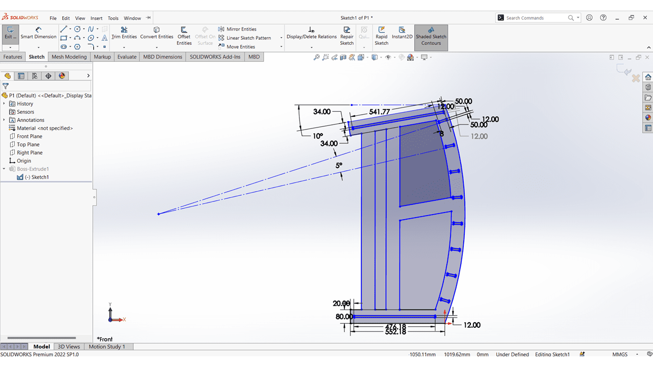
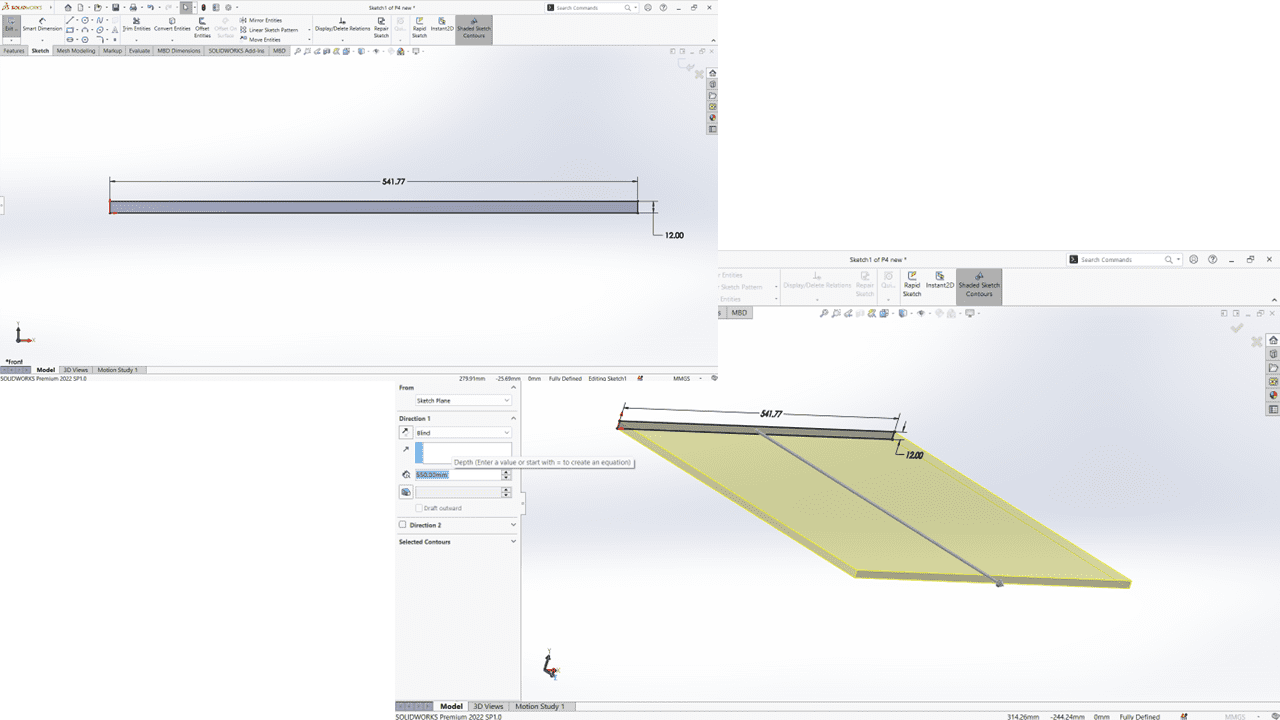
This is the overall dimensions of the podium
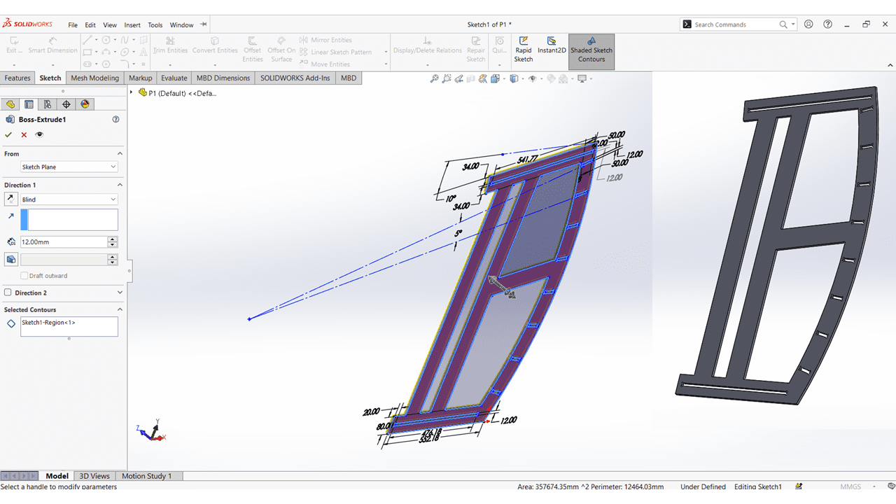
I extruded the first part of the podium with a thickness of 12mm. I want two more parts like this one.
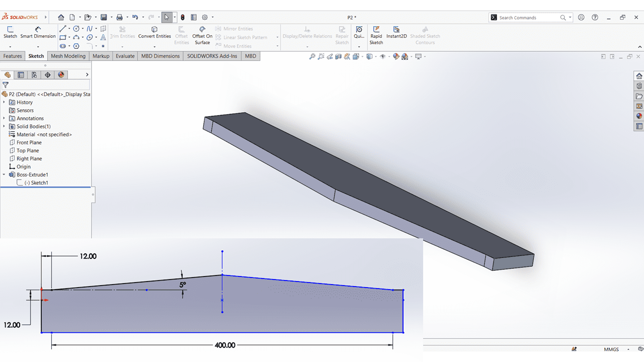
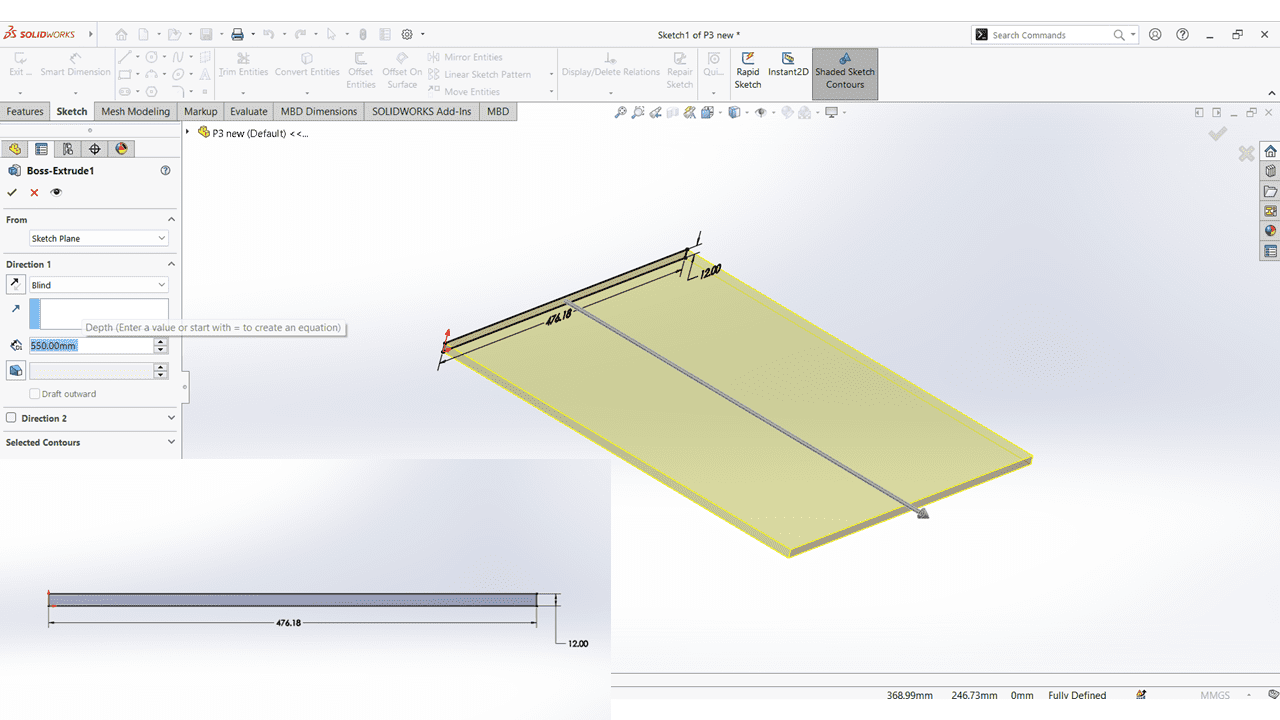
These are all the parts of the podium with dimensions
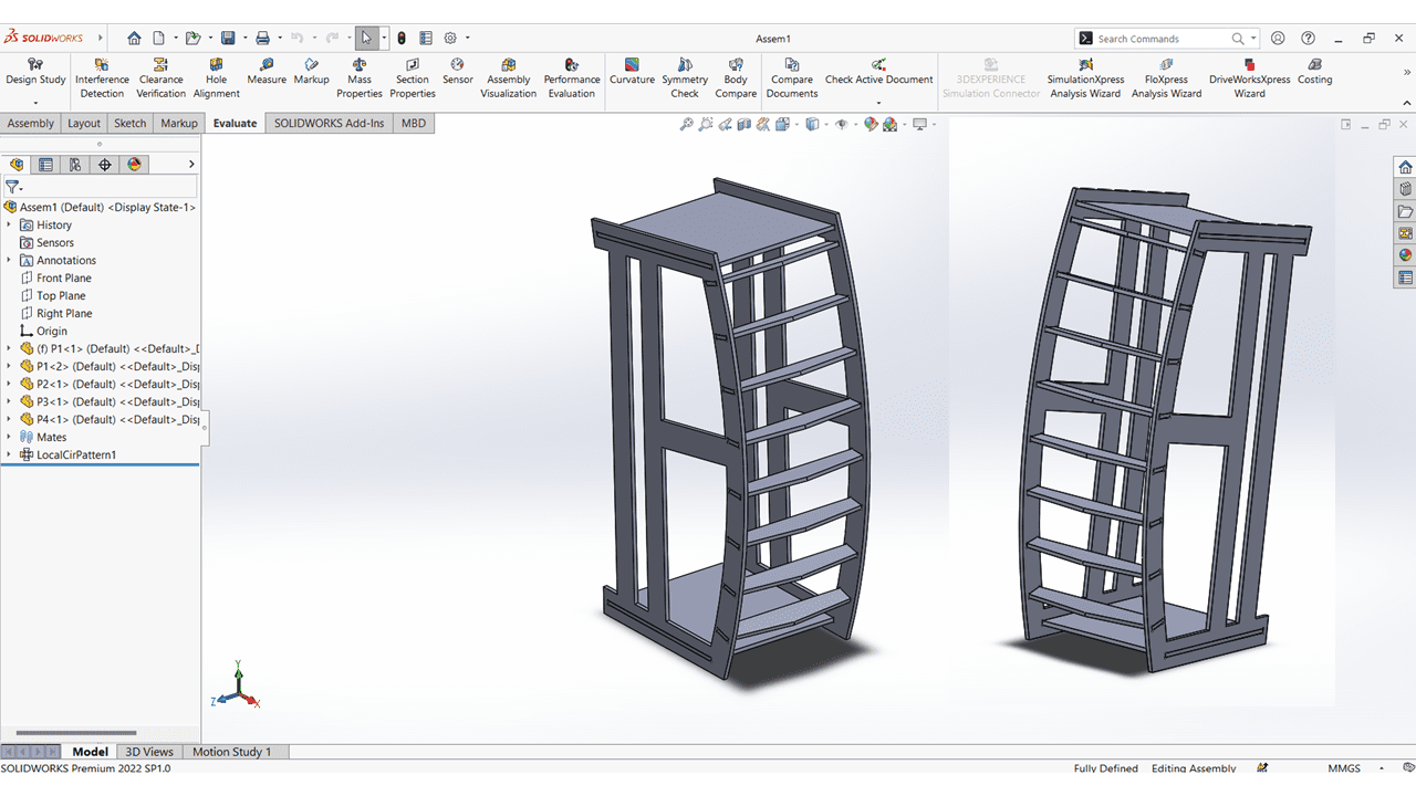
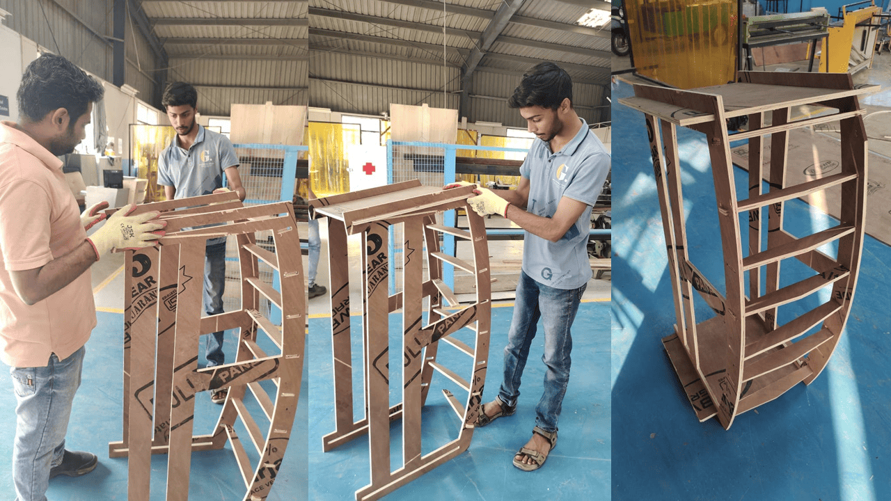
I have assembled all the parts using mates in SolidWorks. I used coincident, parallel, and tangent constraints, and this is the final output that I obtained after the assembly.
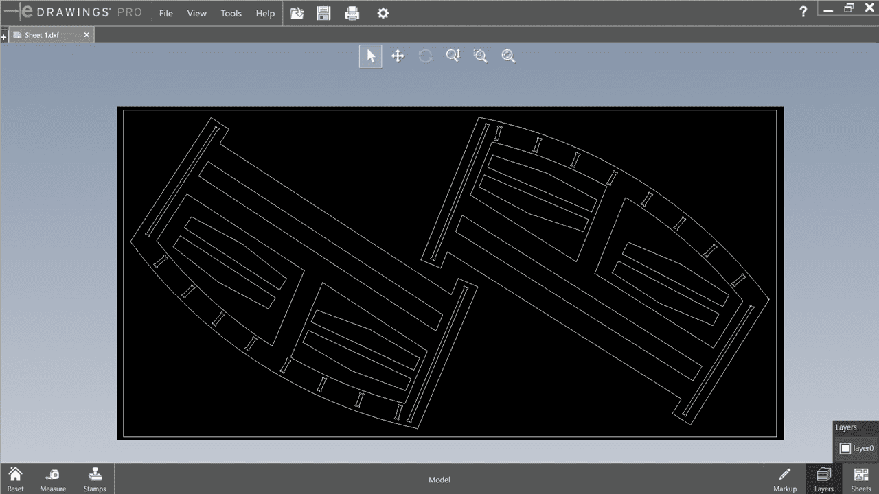
After that, I exported those files into .dxf format. While doing this, I arranged all the parts on a sheet measuring 2400mm x 1200mm.
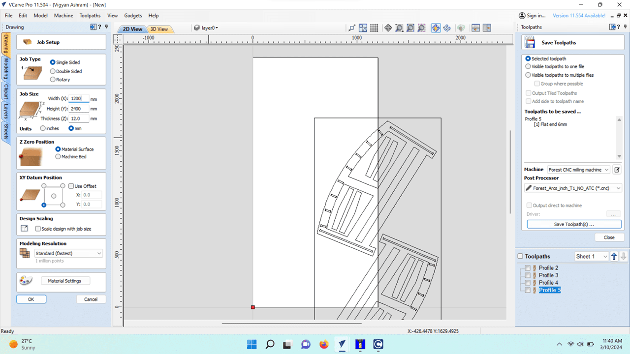
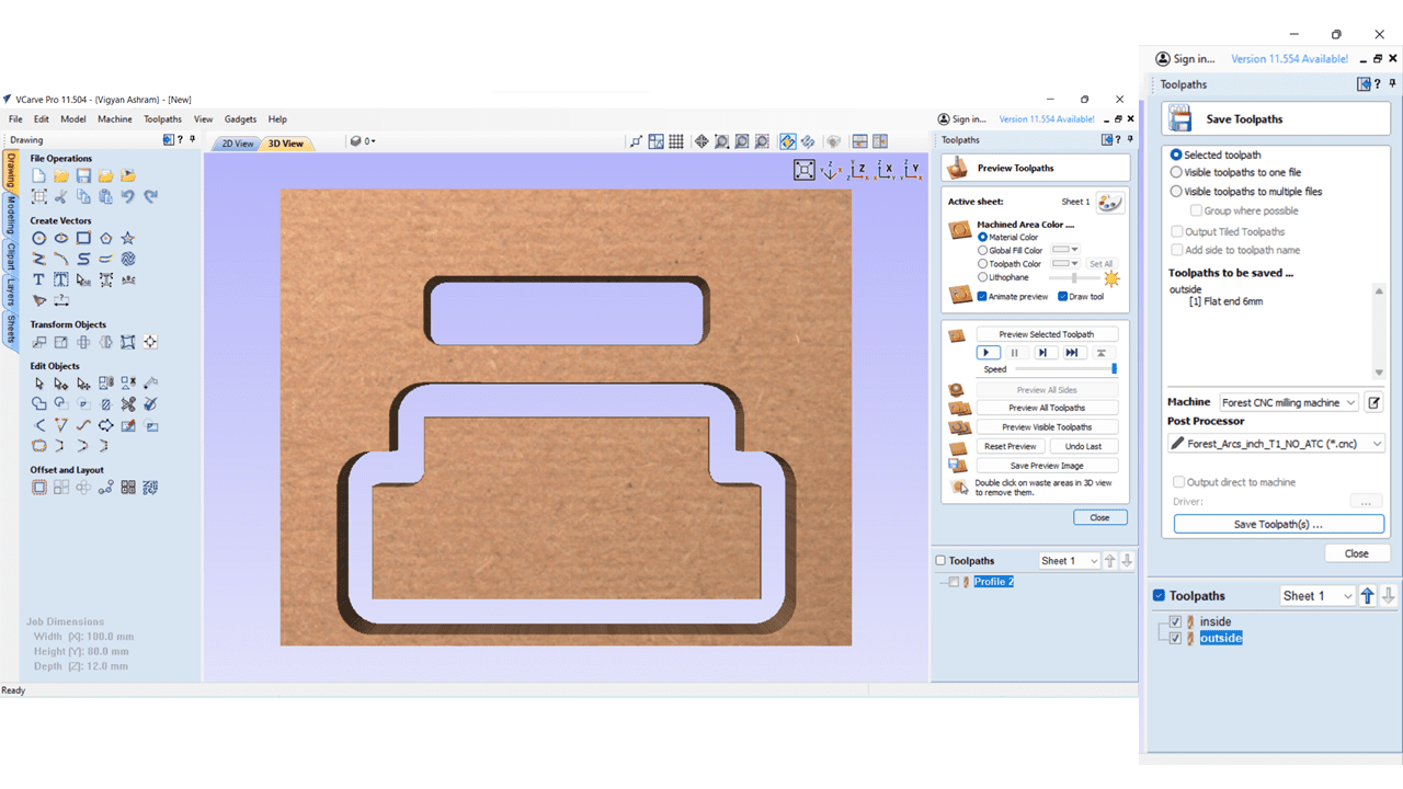
Then i import the my .dxf file into Vcarve pro of version 11.504 software which is generate the toolpath for cutting operation. In that Firstly i set the job size which is 1200mm X 2400mm
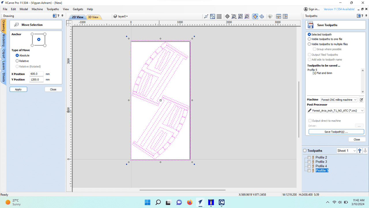
then move the file to the properly using move command which is activaed by m key. and set the x and y position of the design.
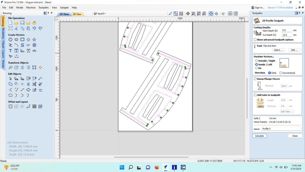
For cutting there are three types of toolpaths:- online, inside, outside. For all the inside part i want inside cut, so i selected all the inside part and give them inside cut.
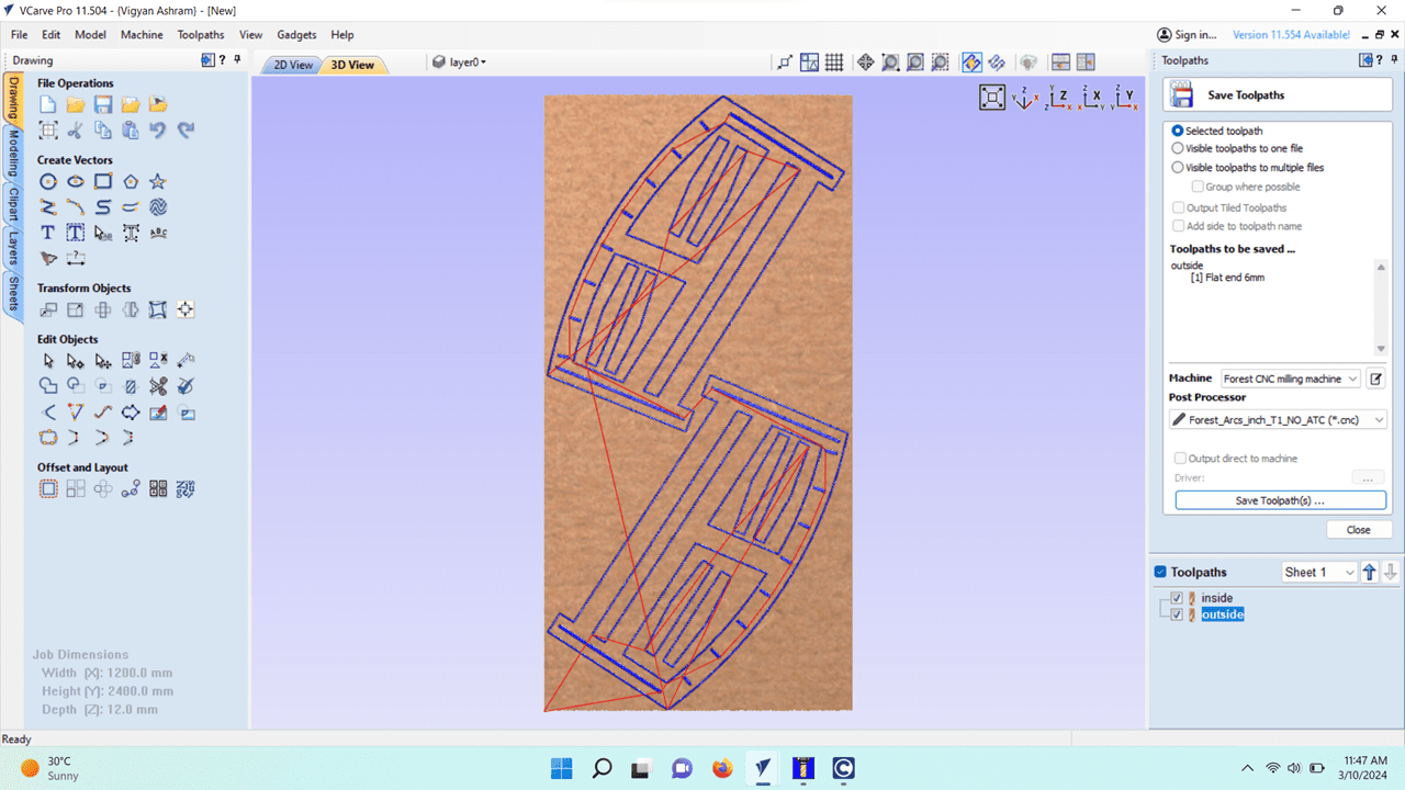
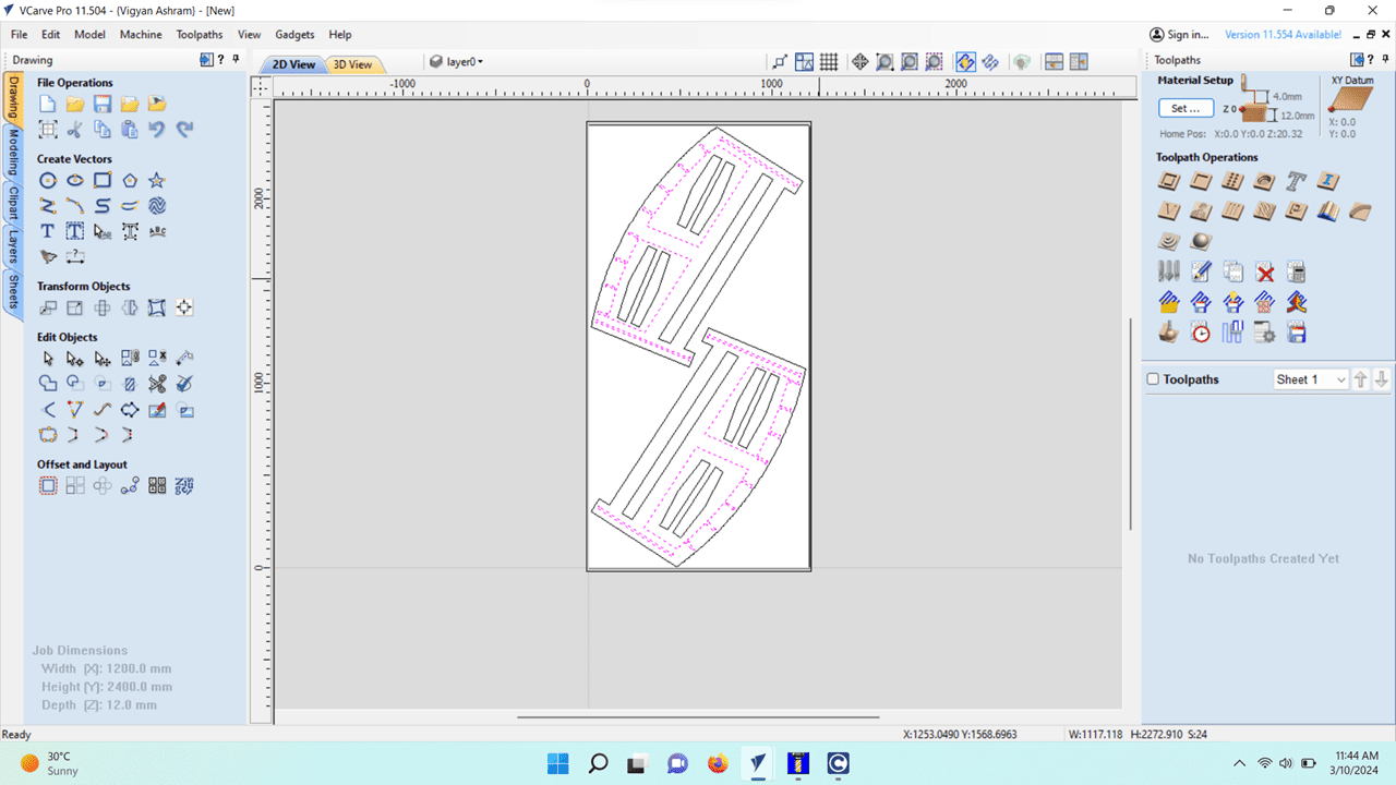
This is the final 3D representation of the toolpath. The final output will look like this.
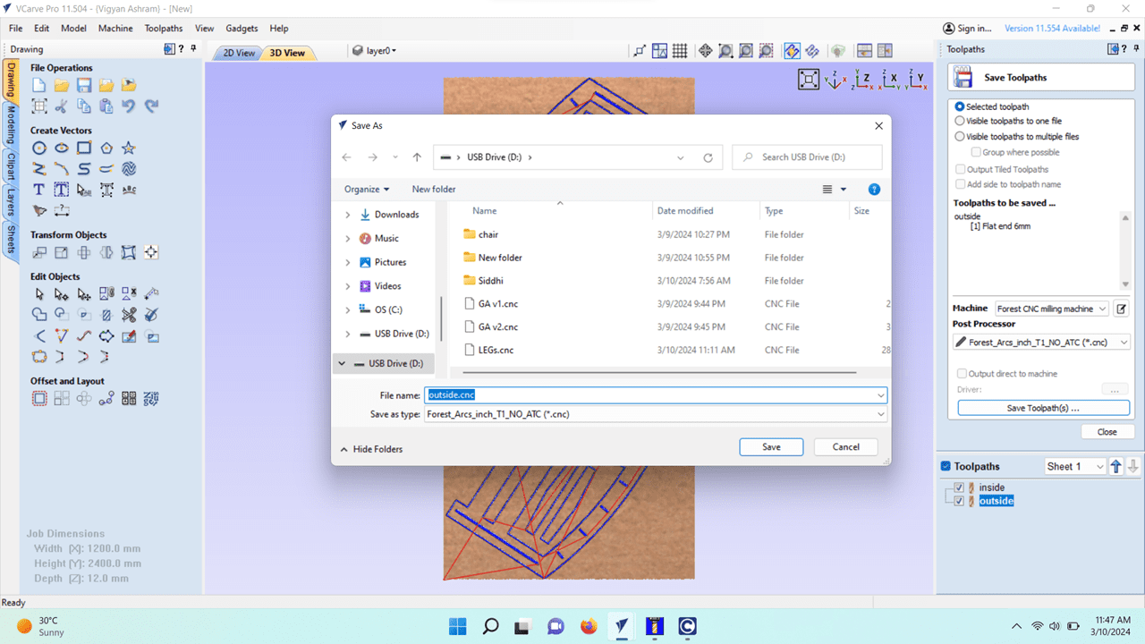
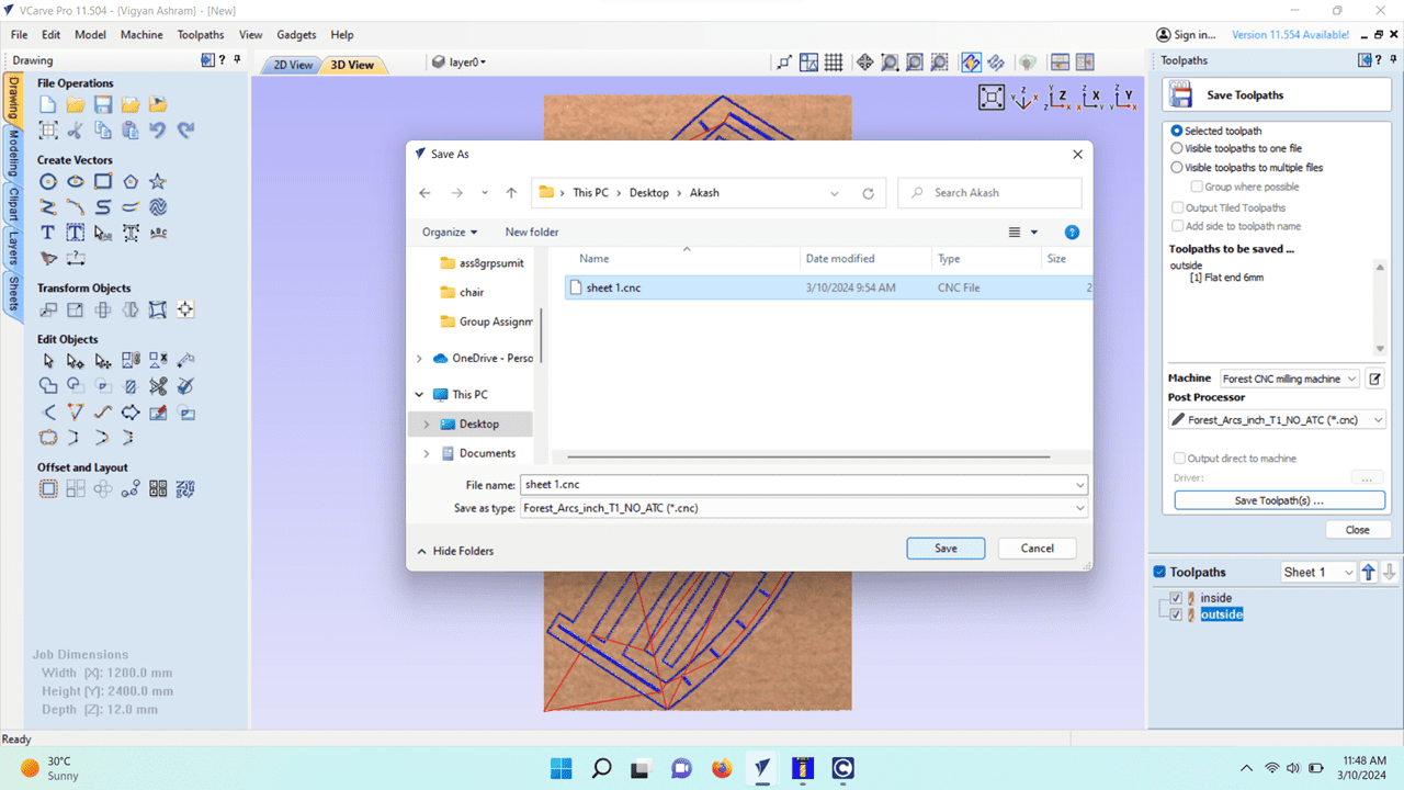
I saved that toolpath with the extension of .cnc
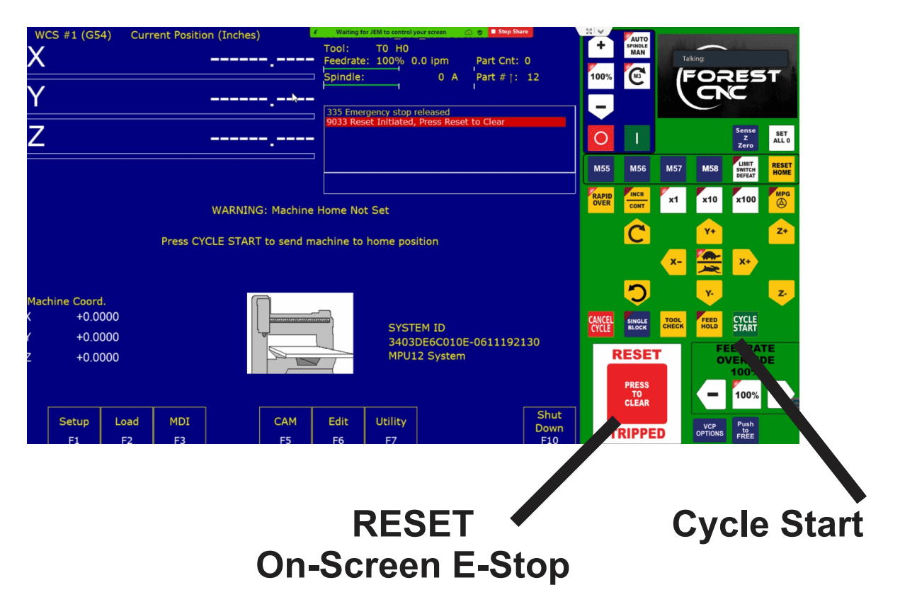
1) Turn on the machine by pressing the green power button, wait 30 seconds,
Then open the control software from your desktop.
2) Press reset button twice until reset cleared is shown. Then Hit Cycle Start
to send the machine home.
3) Secure your raw stock on the Router Table.
4) Use the jog buttons to manually move the machine to the lower left corner of the
material just touching the surface.
Note:
If the machine has a safety shield it will move in slow jog
If the INC/CONT lite is lit the machine will only move
the selected incremental distance
All devices with measuring components need to be set to zero before use, from scales
and timers to mills and routers there are no exceptions.
6) Once the machine is in position we will zero each axis. Start by going into Setup
by hitting F1, hit F1 again to go into Part.
7) Once in Part your screen will look like below. Use F10 to set the X to zero, Hit F1 to go to the Y axis.
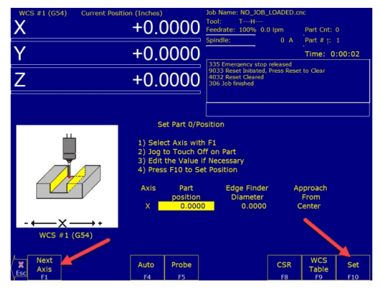
8) Hit F10 to set the Y Axis to zero, Hit F1 to go to the Z axis, Hit F10 to zero Z axis. Press the ESC key twice to return to the main menu. Jog the Z axis up so it is not touching the material.
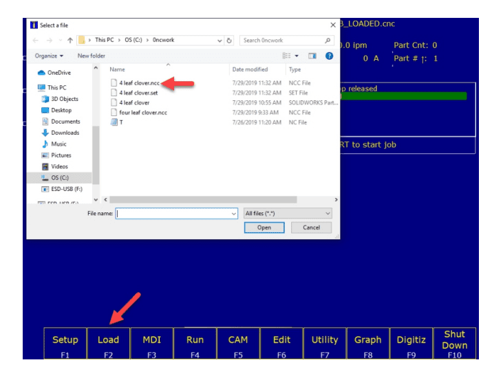
9) To load your G-Code File (ie .ncc .cnc .nc )
Press F2 Load, browse to C:\0ncwork, and select
the name of your project ie.. 4 leaf clover.ncc,
Press Open, Your project job name will now show in the top middle of the screen.
10) To verify the job press F8 Graph, This will show your toolpath. You may hit F1 to show the tool path in a different view, This will also give you a time estimate at the top of the screen. Press ESC to exit graph when done.
11) Now we are ready to machine your part. If there is a door or safety shield, Make sure the safety shield is closed. Press the cycle start button twice.
12) After part is finished jog tool away from part, remove the part.
13. To Exit the control,
Press F10 Shut Down,
Press F1 Park ( then Cycle Start)
Press F9 Exit CNC12
by following the above steps i load the file in the software of inside and outside cut.
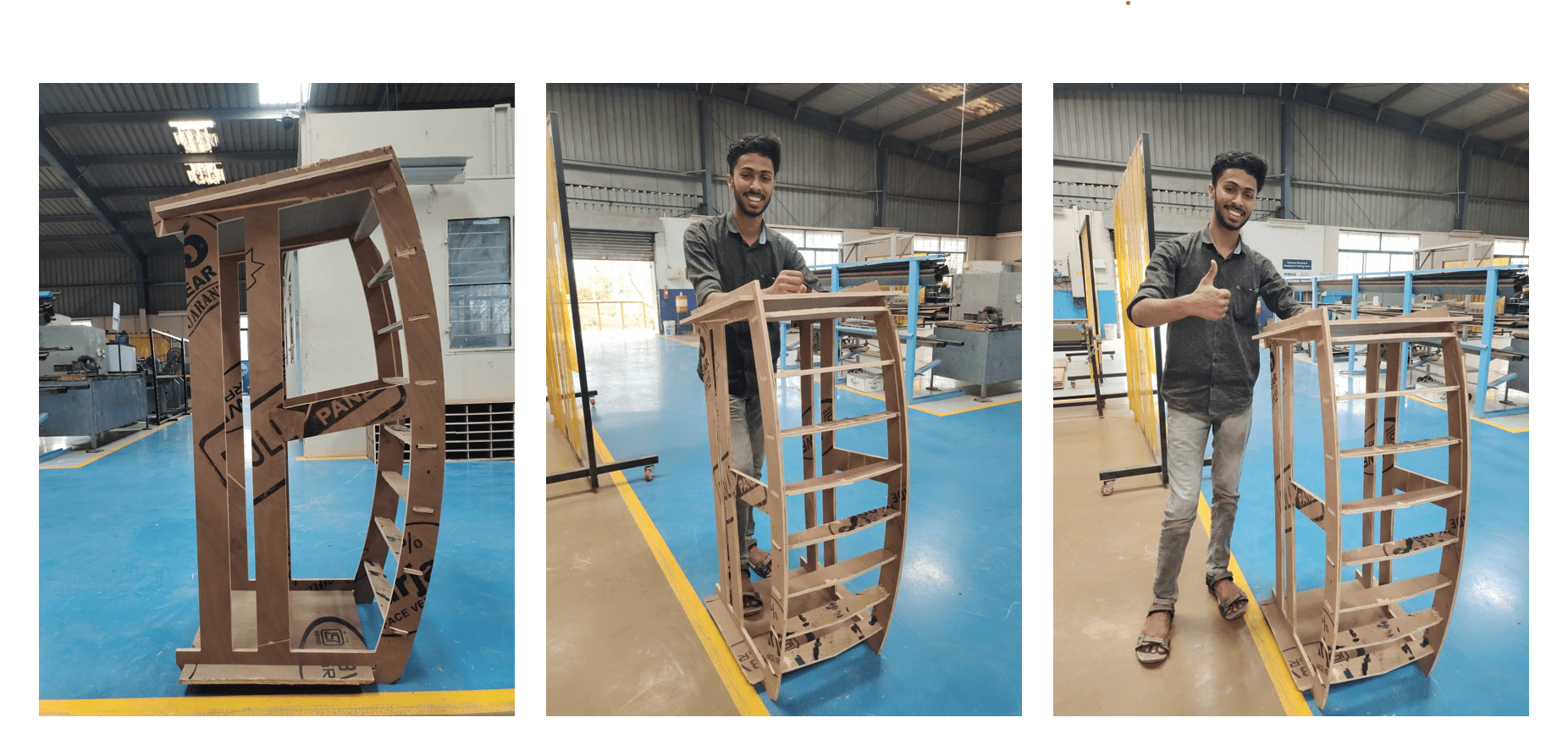
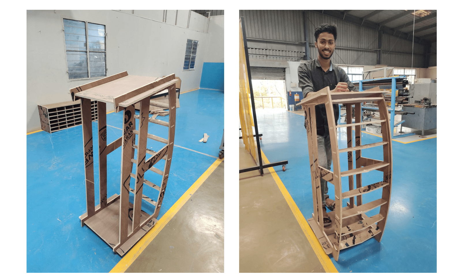
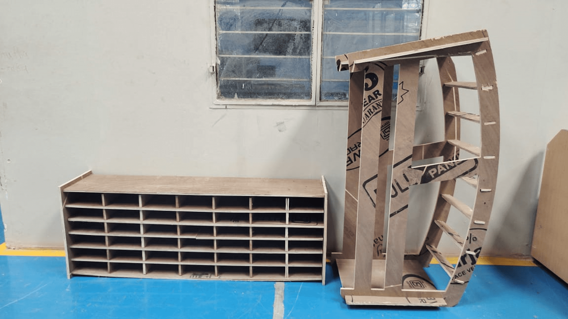
This is how I assembled the podium
This is the final output i got for this week.
VCarvePro --Documentation
Vcarve-pro Download
VCarvePro Mannual