This week, I will be focusing on electronic production, which encompasses various aspects such as PCB (Printed Circuit Board) fabrication, PCB materials, board houses, components, breadboards, and the assembly of components. Additionally, I will be delving into CAM (Computer-Aided Manufacturing), where I will utilize mods for path generation on a PCB milling machine.
In this section, I am documenting various PCB fabrication techniques, the required materials, machines, and different tools needed.
This process involves immersing the PCB in chemical solutions, such as acidic or alkaline solutions, to remove unwanted excess copper from the PCB. The PCB is fully submerged in the solution to ensure uniform corrosion occurs across its surface. Concentrated Hydrochloric Acid or Concentrated Nitric Acid is commonly used as the solution in this process. There are two types of etching processes: dry etching and wet etching. Both processes utilize corrosion as the reactive force.
ACETIC ACID = CH3COOH (also written as CH3CO2H or C2H4O2) White Vinegar
CITRIC ACID = C6H8O7 Sour Salt dry powdered form
HYDROCHLORIC ACID / MURIATIC ACID = HCl Swimming Pools to reduce alkalinity
HYDROGEN PEROXIDE = H2O2 First Aid Antiseptic Solution, & Mild Disinfectant for wounds
Sodium chloride = NaCl The chemical name for Salt
Copper sulfate = CuSO4
1. Always use proper equipment such as goggles, gloves, face mask and aprons when mixing or etching.
2. Use appropriate devices, either glass or plastic, for mixing.
3. During the process, avoid direct physical contact with the etchant.
4. Utilize a device to hold the specimen securely.
5. Working within a properly designed chemical fume hood is a good practice.
6. After the etching process, refrain from placing the specimen directly under a microscope, as it may damage the microscope's lenses.
7. Eching chemicals should be disposed of properly according to local regulations to prevent harm to environment.
PCB Milling is also called Isolation milling, it is the process by which copper or the metallic portion from the sheet of printed circuit board(PCB) is removed to recreate the pads, structures and the signal traces and paths according to tool path provided to the machine or layout file
FR1 (phenolic paper) : Phenolic paper is a material often used to make printed circuit board substrates (the flat board to which the components and traces are attached). It is a very tough board made of wood fibre and phenolic polymers. It is most commonly brown in colour, and is a fibre reinforced plastic. These PCB materials are known as FR-1 and FR-2 – FR-2 is rated to 130 °C, FR-1 is rated to 105 °C.
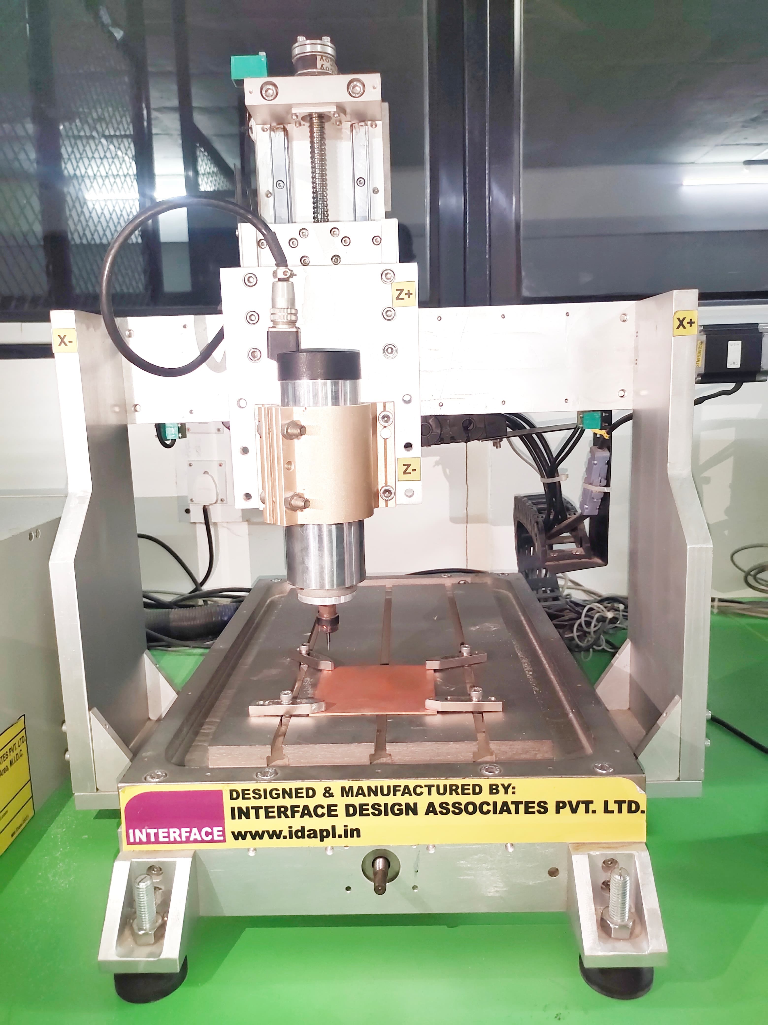
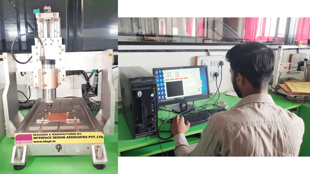
In this assignment, we are going to characterize the design rules for a PCB milling machine and utilize the milling process for PCB fabrication.
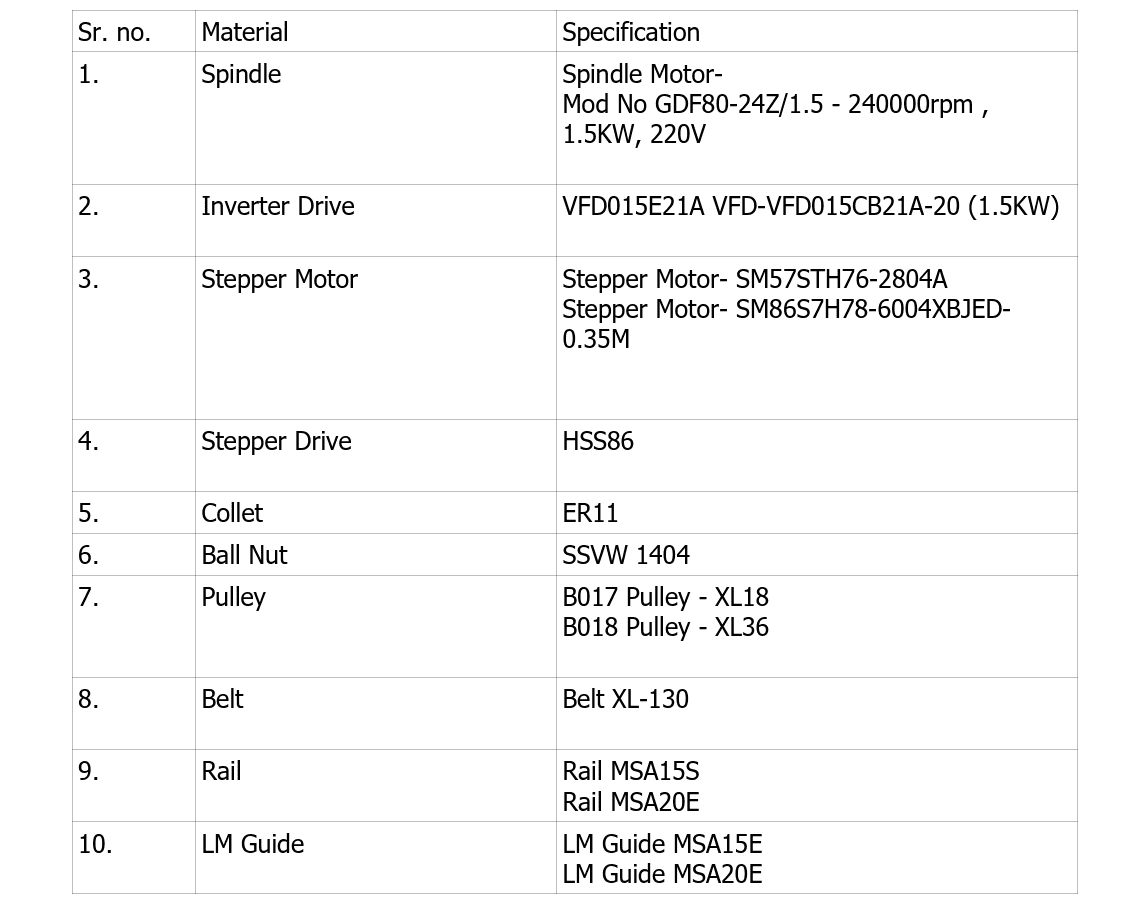
The manufacturer of the machine is Interface Design Associates Pvt. Ltd., a local manufacturer in India.
Additionally, we are utilizing the WinMill,
which combines the power of the SC06 with a user-friendly application running under the Windows 7/8/8.1/10 32-bit system.
The SC06 card is a three axis CNC controller which is highly cost effective controller
with following features:
• 4 Axis of digital numerical control
• G & M Code support
• Multiple Operation Modes.
• Manual Mode - Jog, Incremental, Absolute and Home.
• PLC Interface available
• 16 digital inputs and 16 digital outputs. (Additional RemIOV4 card with serial port
comm.)
The CNC controller is a standard PC running Microsoft Windows 7. The motion is
controlled through the SC06 card and the IOs are through an intelligent IO board
(SC04 BOB ISO ). The PLC system forms a part of the CNC application and the PLC
ladder logic program and the GCODE programs are coordinated.
MM3030 (Milling Machine 300mmX300mm) machine can perform different functions like Engraving, Milling, Cutting and Drilling. Different tools of different diameter are required for different operation. Diameter of tool and tool shank is depends upon the collet and drawing dimension.
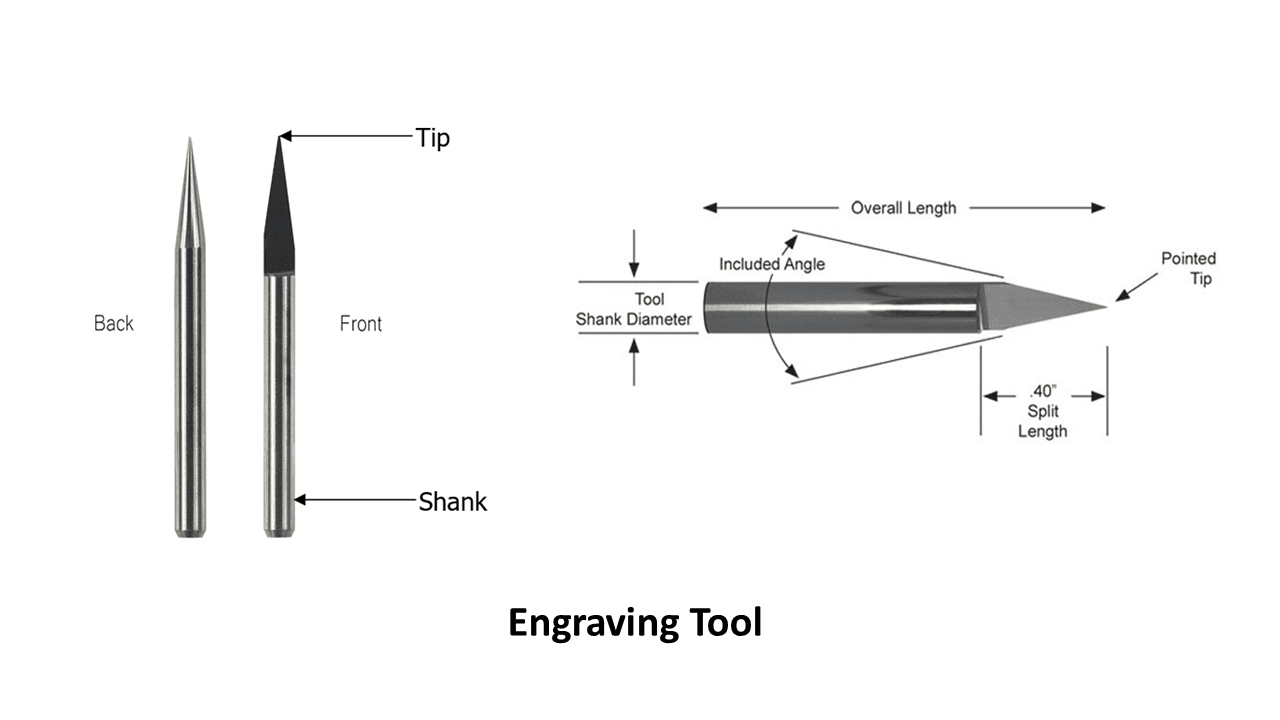
Engraving tools are available in different shank diameter, different tip diameter and also with different split angles. There are also coated and uncoated tools. Coated tools have double life as compared to uncoated tools in normal operation.
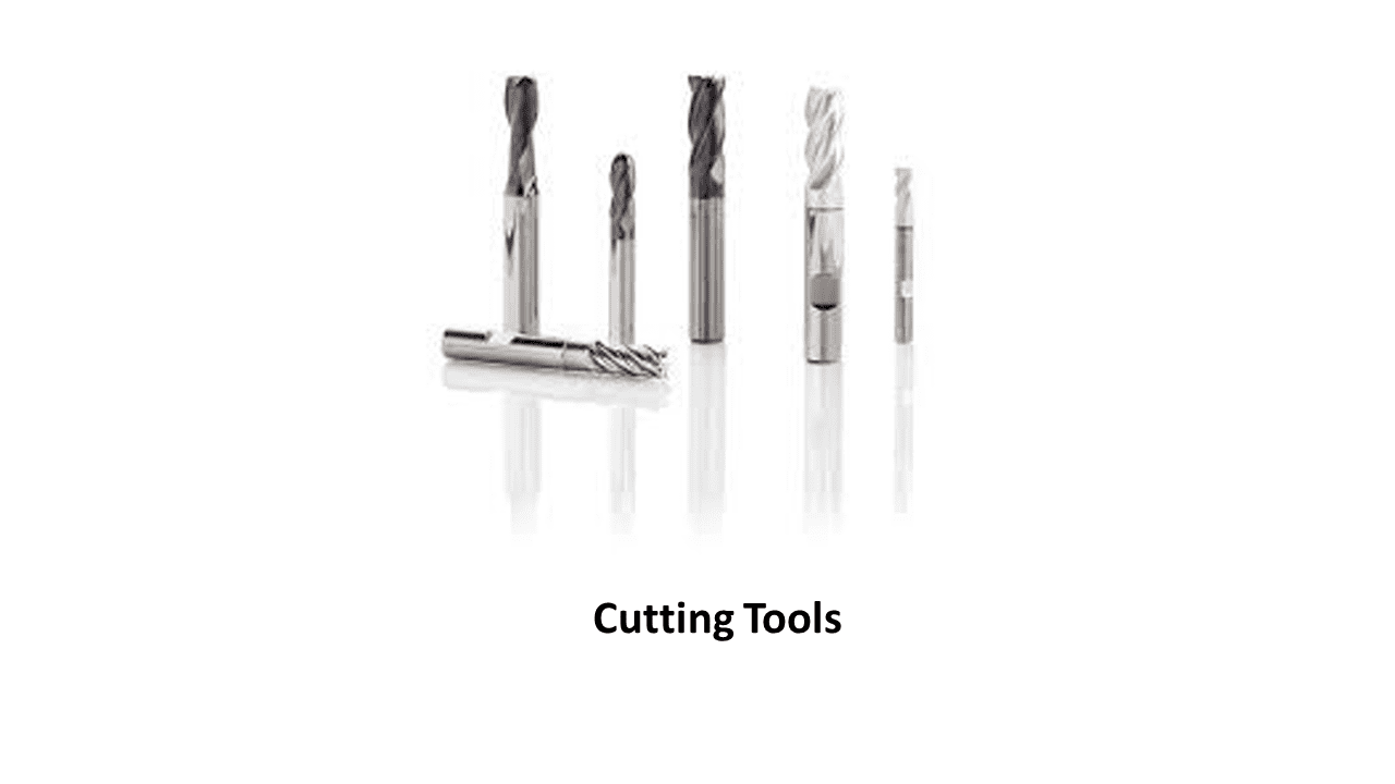
Routing tool is called as End Mill. These tools are also available in different shank sizes and different nosal diameter. There is flat end mill and ball end mill; user can use these tools depending upon their application.
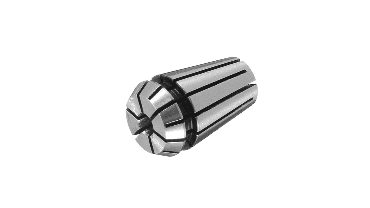
Spindle of MM3030 is with ER11 Collet, therefore always use ER11 collet for MM3030 machine. ER11 series collets have a capacity of 0.020-0.3125 inches. Each ER11 collet has a range of 0.020 inches (0.5mm). The size indicated on the collet is the largest size it can hold and can be collapsed smaller within its collapse range of 0.020 inches (0.5mm). For example, ER11-3mm can grab a round shank from 3mm diameter to 2.5mm diameter.
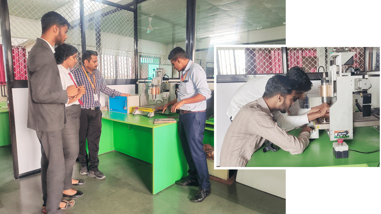
Our local instructor, Dr. Kiran Wakchaure, gave a lecture about the PCB milling machine, then i fix the tool into the spindle properly
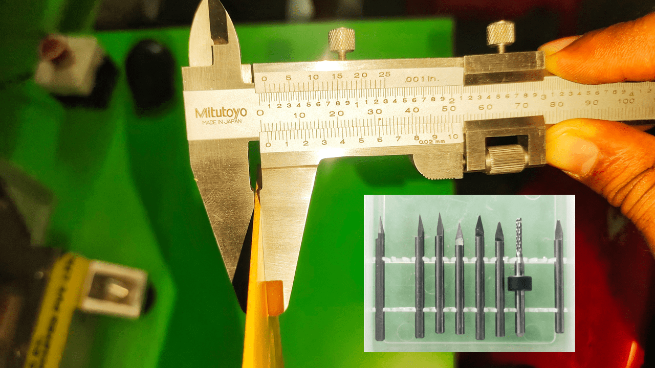
I measured the thickness of the sheet to determine and set the maximum depth of the tool.
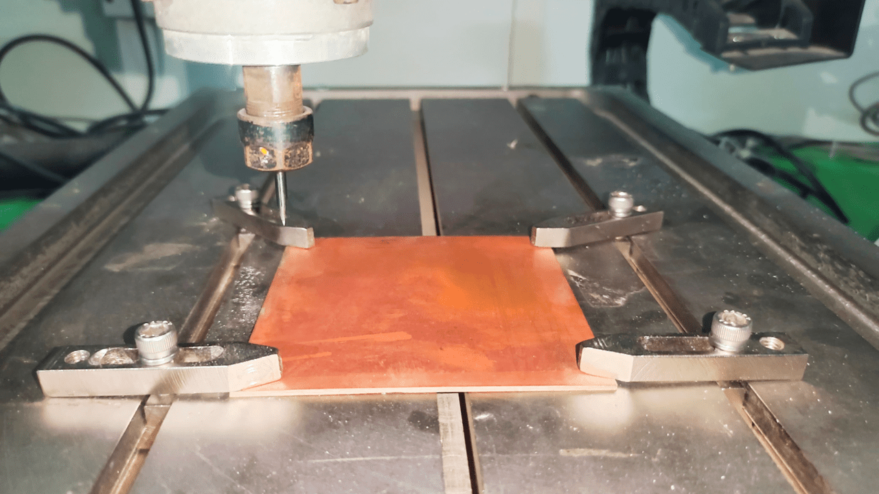
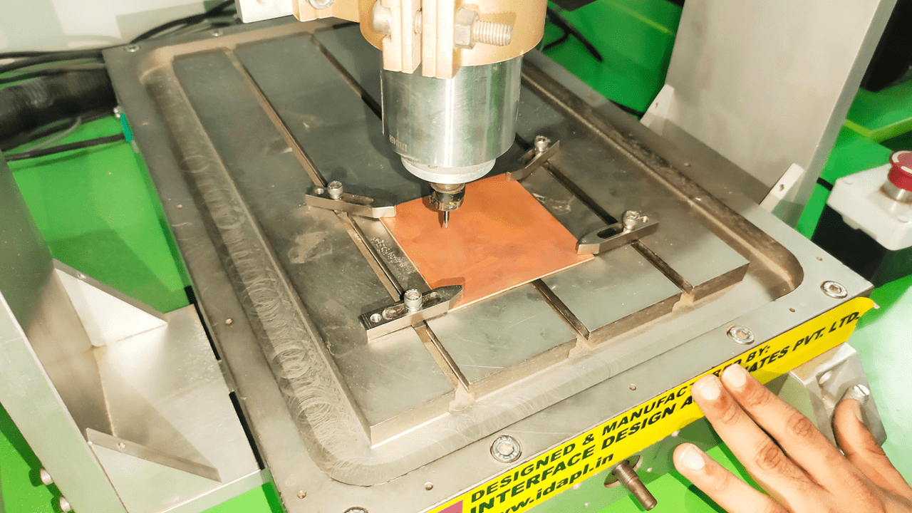
I fixed the sheet using clamps on the workbench, which is a crucial step. Uneven fixing of the material can result in incorrect traces, potentially leading to defects in the PCB.
Then, I loaded the program into the software and properly set the X, Y, and Z coordinates.
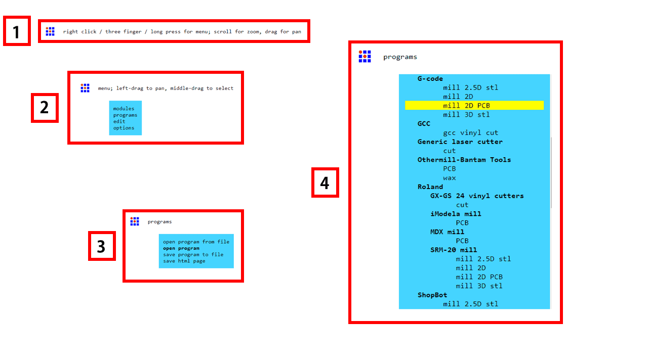
We used the modules for generating the G-code for the machine. For this, I followed the following process: firstly, right-click on the blank page to open the next tab, where we get modules, programs, edit, and options. From there, select the programs option. Then, in the next tab, select the "mill 2D PCB" option, and the program will open.
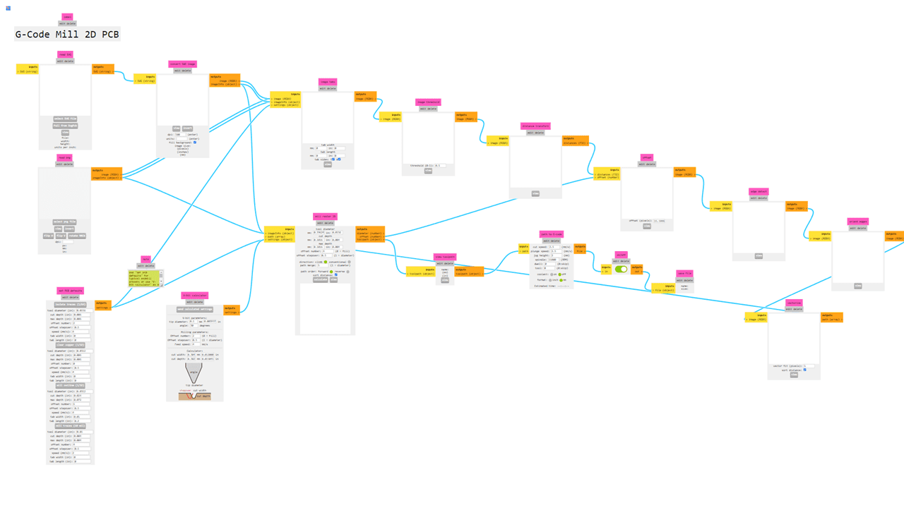
This is the interface of the program, and it is a little bit different from other software, but it is simple to use.
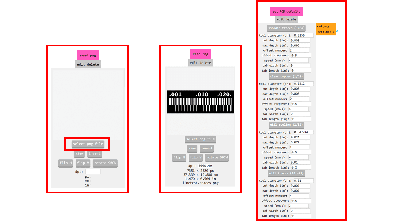
In this program, we can import two types of file formats: .svg and .png. In our case, we will be using the .png file format. After opening the file, go to "Set PCB Defaults" and select the mill outline (1/32).
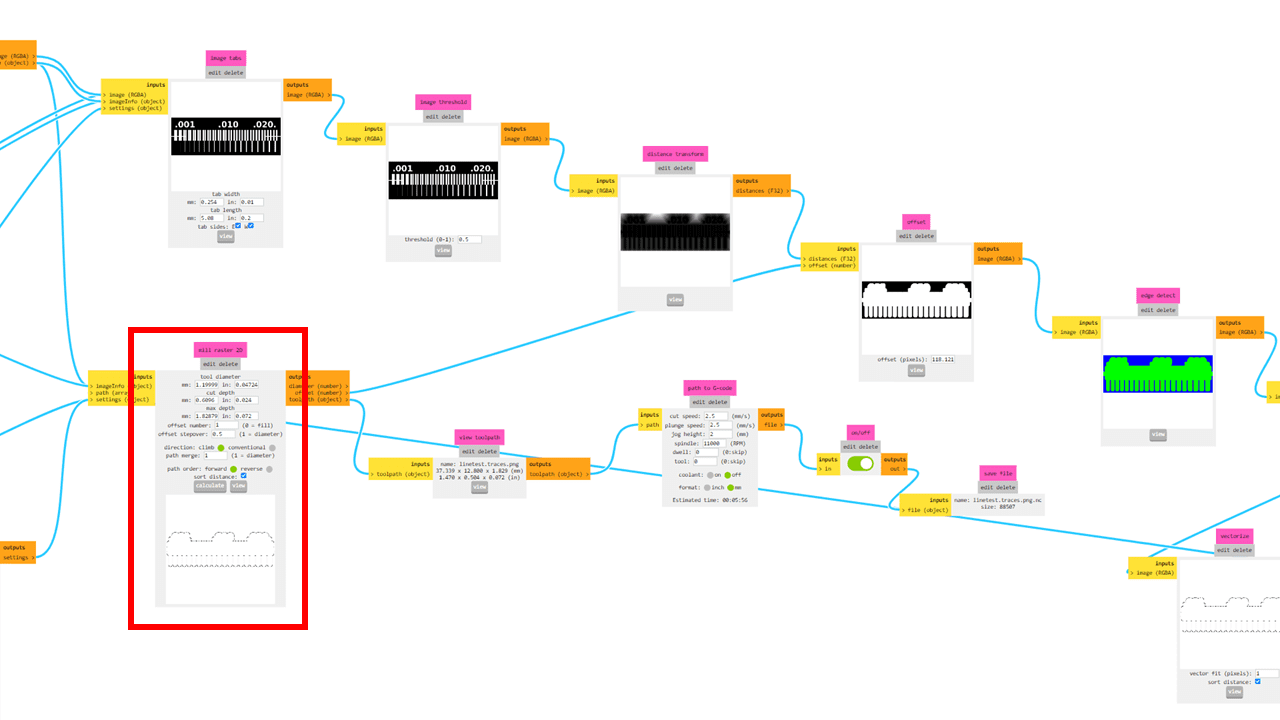
After selecting the mill outline (1/32), proceed to "Mill Raster 2D." Here, we can adjust the tool diameter, cut depth, and the maximum depth of the tool. Then, click on the "Calculate" option. The code file will be downloaded, and we can view the traces by clicking on the "View" button.
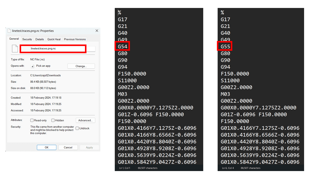
The downloaded file is in the format of .nc. In our case, we have to change the extension of the file from .nc to .gcd for compatibility with our software and the machine. Additionally, we edit the file and make some changes in the G-code, such as changing from G54 to G55.
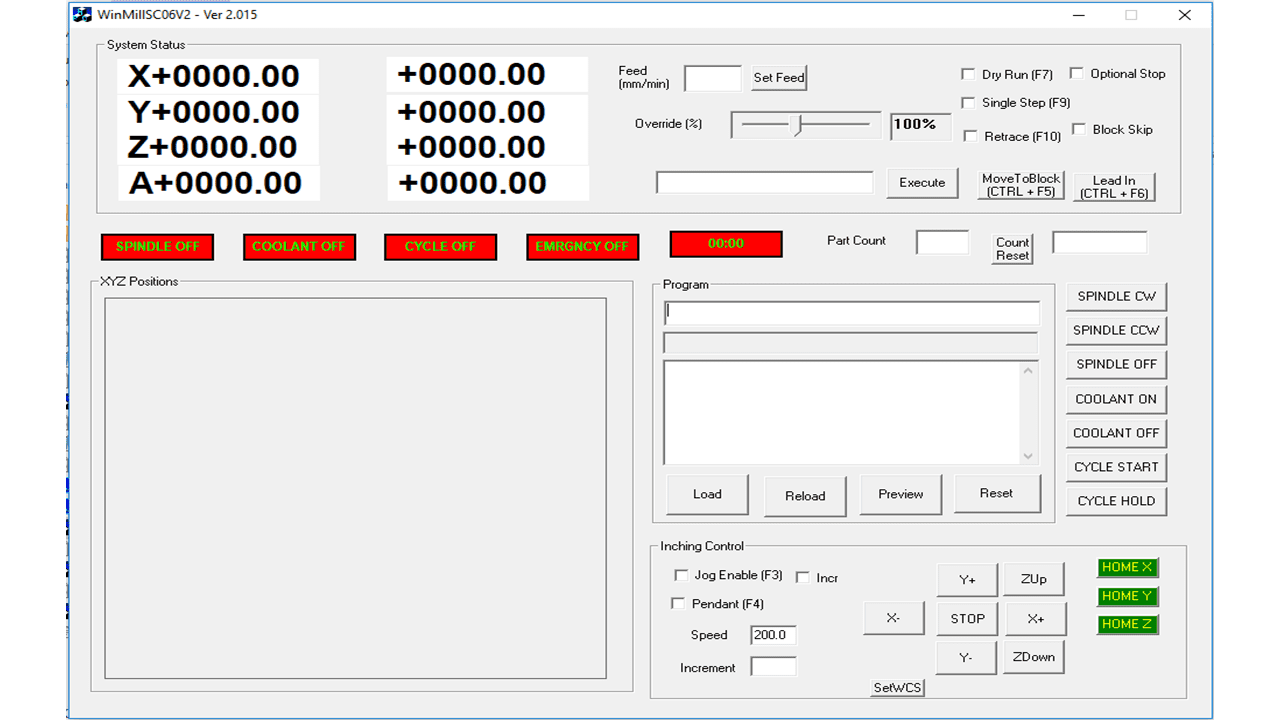
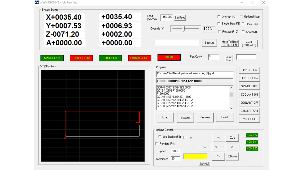
This is the interface of the software used for the PCB milling machine, which is provided by the local manufacturer of our fab lab's PCB milling machine.
The information displayed is:
1. Idle mode of the machine displayed
2. Machine status consisting of the following parameter is displayed:
X, Y, Z and A axis co-ordinates
Feed rate, Override, Dry run, Single step, Retrace, Optional Stop, Block Skip
Spindle ON/OFF and Coolant ON/OFF
Cycle Start and Cycle Hold
Load, Reload, Preview and Reset And Jog control section.
Manual Movement: Manual movement is provided as a sub menu of play menu. Click on Jog Enable on
the play screen to enter into the jog menu.
There are three options for Jogging:
1. Jog Enable: Once Jog Enable is selected, the mechanism moves in the direction specified by
pressing the buttons X+, X-, Y+, Y-, ZUp or ZDown. The movement stops only
when the STOP button is pressed. The speed of movement is the speed specified in
the Speed option in mm/min. The default speed is 200 mm/min.
2. Incremental: When incremental motion is selected, the mechanism will move with the specified
speed only for the distance specified in the Increment option.
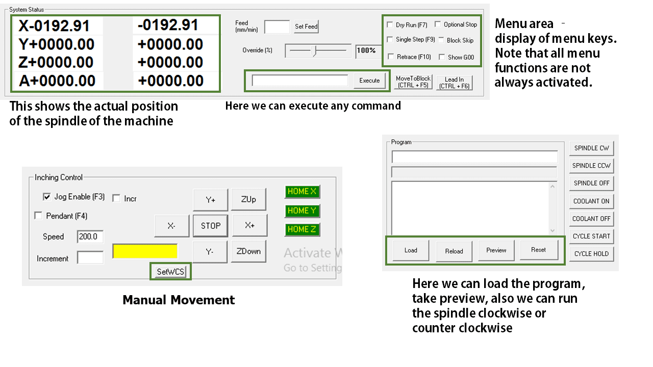
SYSTEM STATUS MENU: It displays the current displacements in the X, Y and Z dialog box while running cycle. In another dialog box shows the remaining displacement while running cycle. The another "Feed (mm/min)" dialog box is used to set Feed rate if user call the codes as micro variable, the system will move with set feed rate. The "Override (%)" dialog box is used to set override speed while running cycle, user can select manually the override feed by adjusting control bar. Options for selecting to run cycle as Dry run by selecting Check box "Dry Run(F7)". If user select this option the only X axis and Y axis movement will happen, the Z axis movement will not consider. This dry run option is useful for verification of newly generated g-code. The another check box for "Single Step (F9)" is used to run cycle in single step mode. If user select the Single Step check box and execute, the system will executes current block of G-code by indicating the command block in "Execute" dialog box. Once first command execution get done, it ready to execute next block which will pop up in "Execute" dialog box. The "MoveToBlock(CTRL + F5)" is used to skip g-code block which are ready to execute.
CONTROL MENU: The Control Menu is used to control Inputs & outputs like Spindle ON/OFF, Coolant ON/OFF, Cycle Start, Cycle Hold. User can turn ON the Spindle by using buttons "SPINDLE CW" for clockwise direction and "SPINDLE CCW" for counter clockwise direction, to Turn OFF the Spindle press "SPINDLE OFF" button. Similarly for Coolant ON/OFF press "COOLANT ON"/"COOLANT OFF". For Cycle starts and Cycle hold use "CYCLE START" and "CYCLE HOLD" buttons.
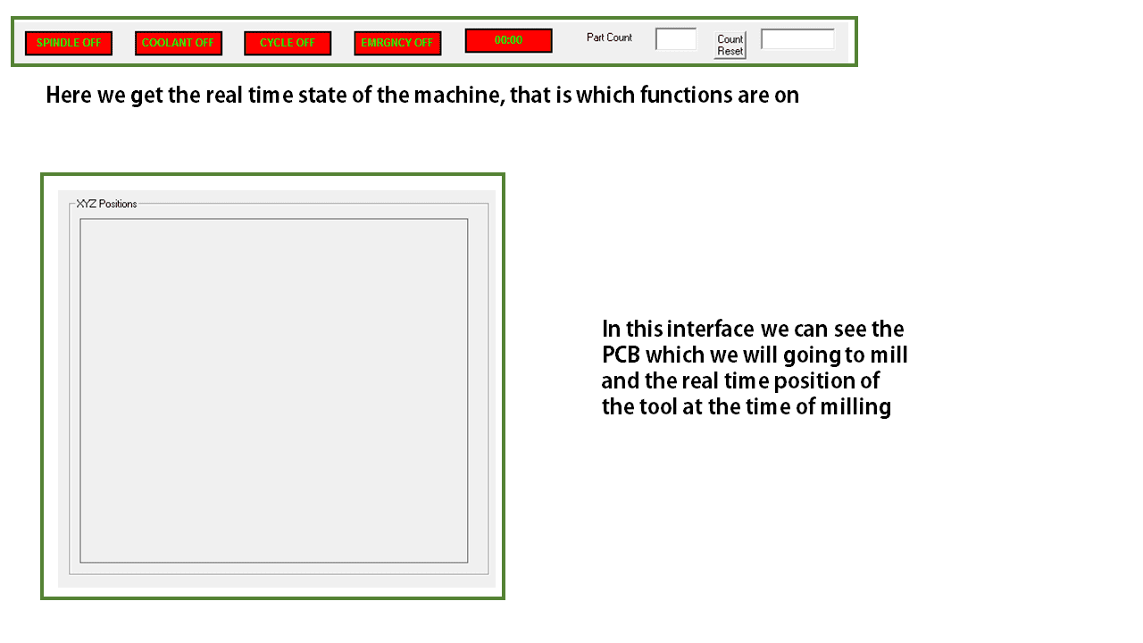
Indication Window: In indication window it will indicates the status of Spindle, Coolant, Cycle ON/OFF, Emergency ON/OFF, Cycle time. For OFF condition it will indicate in Red colour for respective status tab and for ON condition it will indicates in Green colour. In "Part Count" dialog box it will show cycle counts, the count will increment after completing every cycle. To reset part counts use "Count Reset" button.
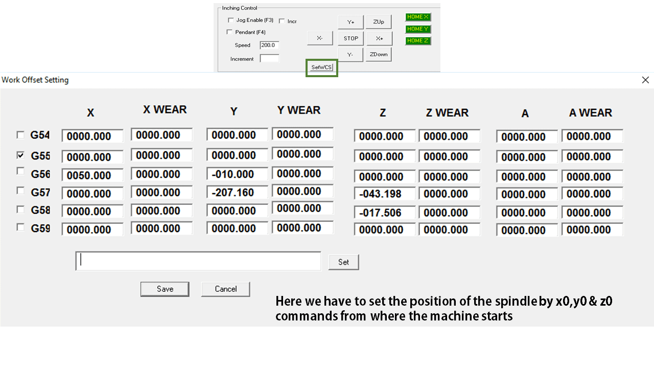
This is Work Offset setting in which we can set the co ordinates of the spindle
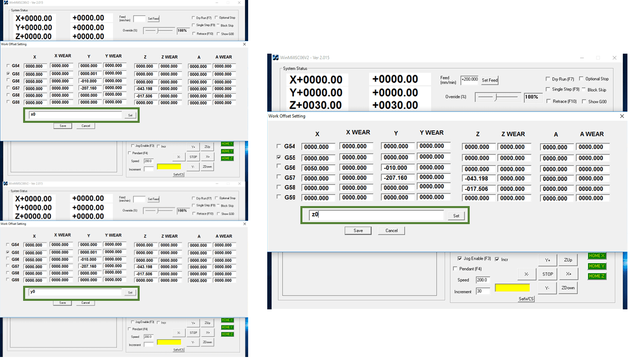
Enter X0 then click set button. Repeat the same for other axes. After setting the values click on save button to save those values.
We have downloded these files from the electronic production week page for the Characterization of our PCB milling machine
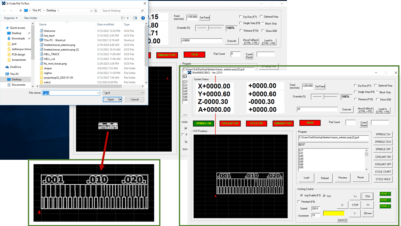
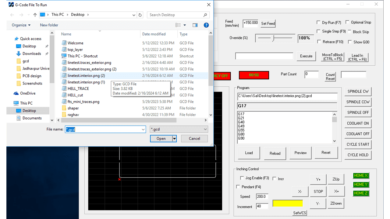
I used the 'load' button to import the file into the software. Then, I conducted a dry run of my PCB to properly understand how much material and space are being utilized for this PCB.
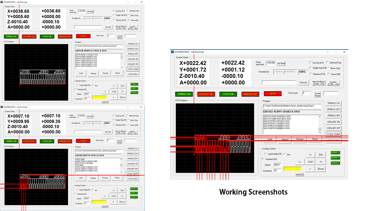
On the display, it will show the toolspath of the real-time operation of the machine. However, there is a software bug causing the path to extend beyond the window.
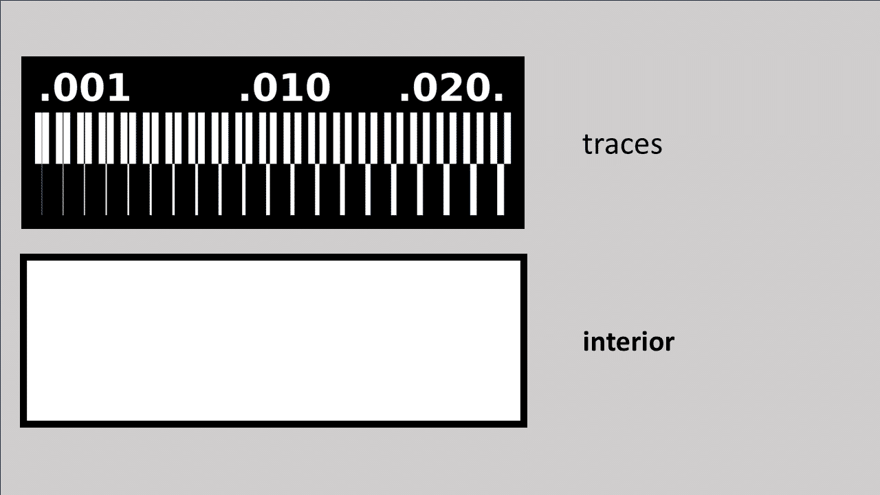
Then, I changed the tool for cutting the interior of the PCB and clicked the reset button to reset the program. Afterward, I used the load button again to load the program for the interior and cut the outline of the PCB.
again it will display the toolpath of the spindle of the milling machine.
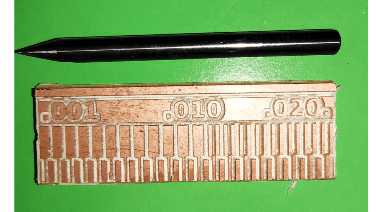
This is the output i got from the milling machine.
More information about group assignment
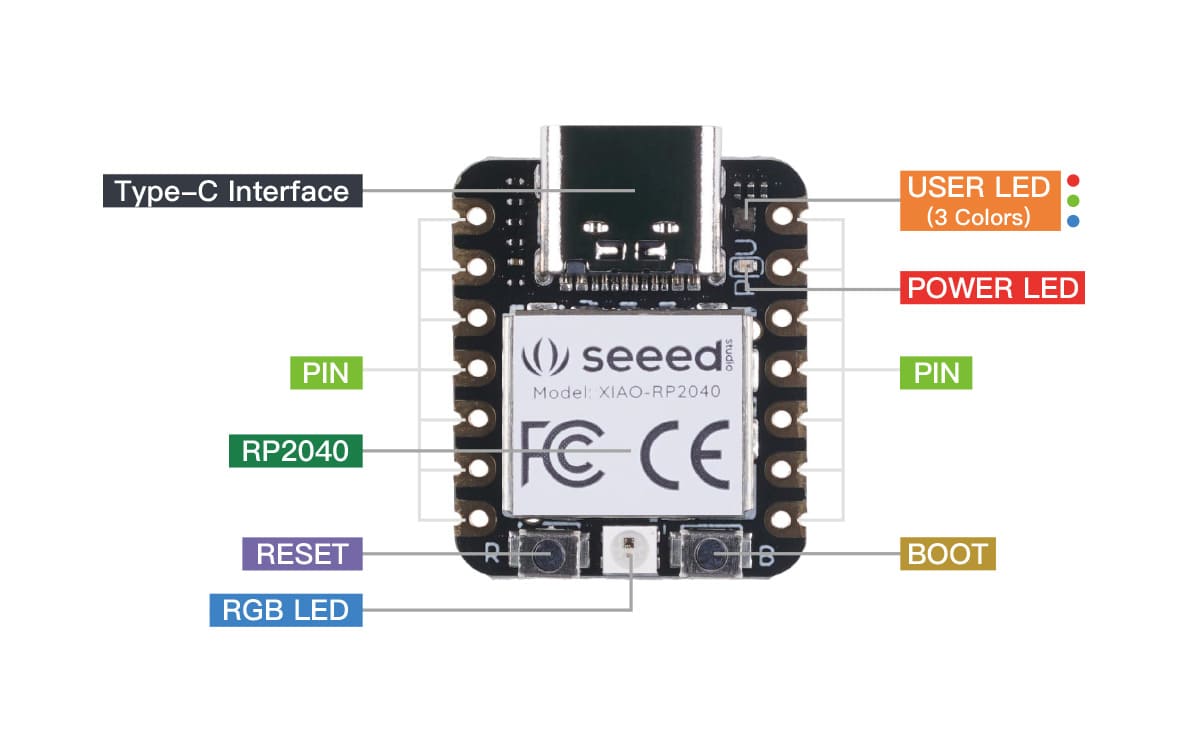
First, we are going to connect the Seeed Studio XIAO RP2040 to the computer and upload a simple code from Arduino to check whether the board is functioning well.
for the installation of the Libraries in Arduino IDE i refered the tutorial of XIAO RP2040 with Arduino
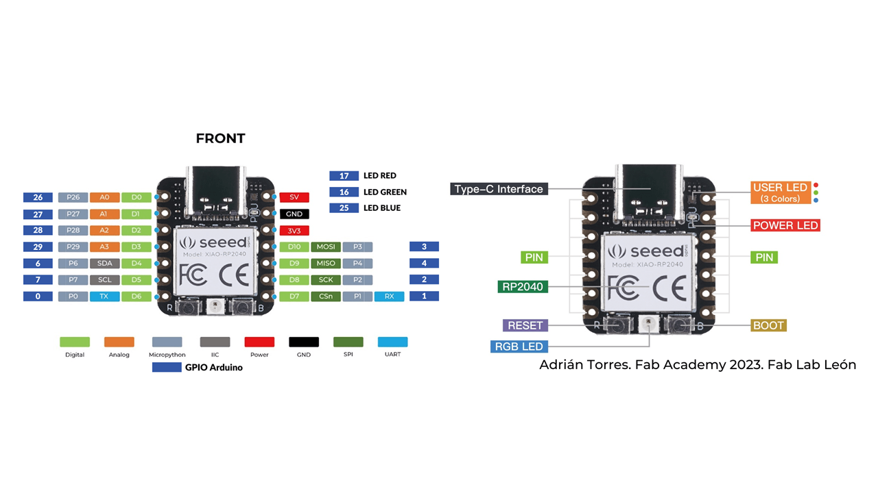
The Seeed Studio XIAO RP2040 contains 11 digital pins, 4 analog pins, 11 PWM Pins,1 I2C interface, 1 UART interface, 1 SPI interface, 1 SWD Bonding pad interface.
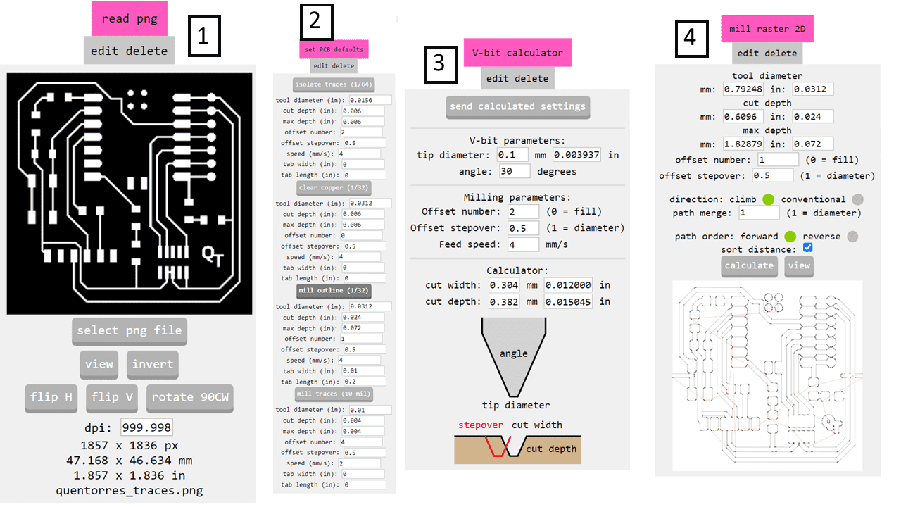
I imported the image by using the 'Select Image' button. Then, I chose the 1/32 mill and opted to use the V-shaped tool for milling the PCB. I didn't make any alterations and left the settings unchanged before clicking on 'Calculate' to generate the G-code.
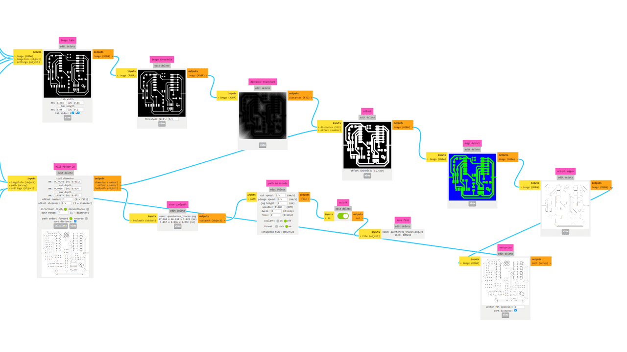
This is how the interface of MODs looks. It provides the G-code and displays the image with varying contrasts.
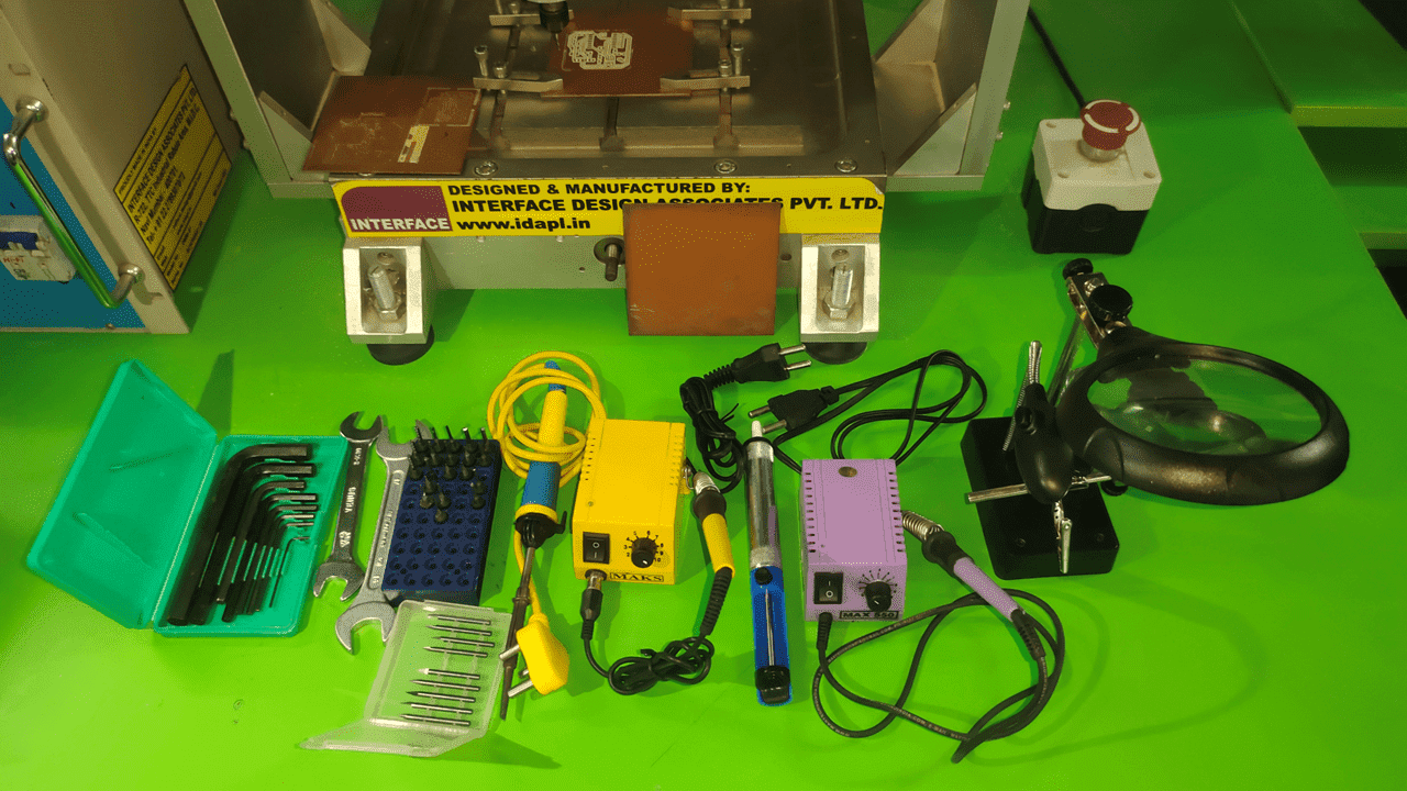
These are some equipments we used in this week, FR1 (phenolic paper), Allen Key Set, A soldering station is a device used for soldering, which is a process of joining metals together using a heated metal filler. The station typically includes a base unit that houses the power supply and controls, and an iron that heats the solder. A soldering iron is a hand-held tool used for soldering. It consists of a heated tip that melts the solder, and a handle for gripping the iron. A helping hand is a tool that holds and magnifies objects, making it easier to solder them. The magnifier in the image is typically used to see small components and solder joints more clearly. and the milling tools of V-shaped
I used nuts and bolts to fix the material on the bed of the machine.
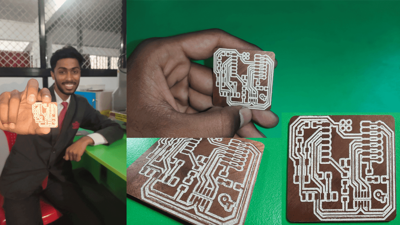
This is the output I obtained from the PCB milling machine using a V-shaped tool.
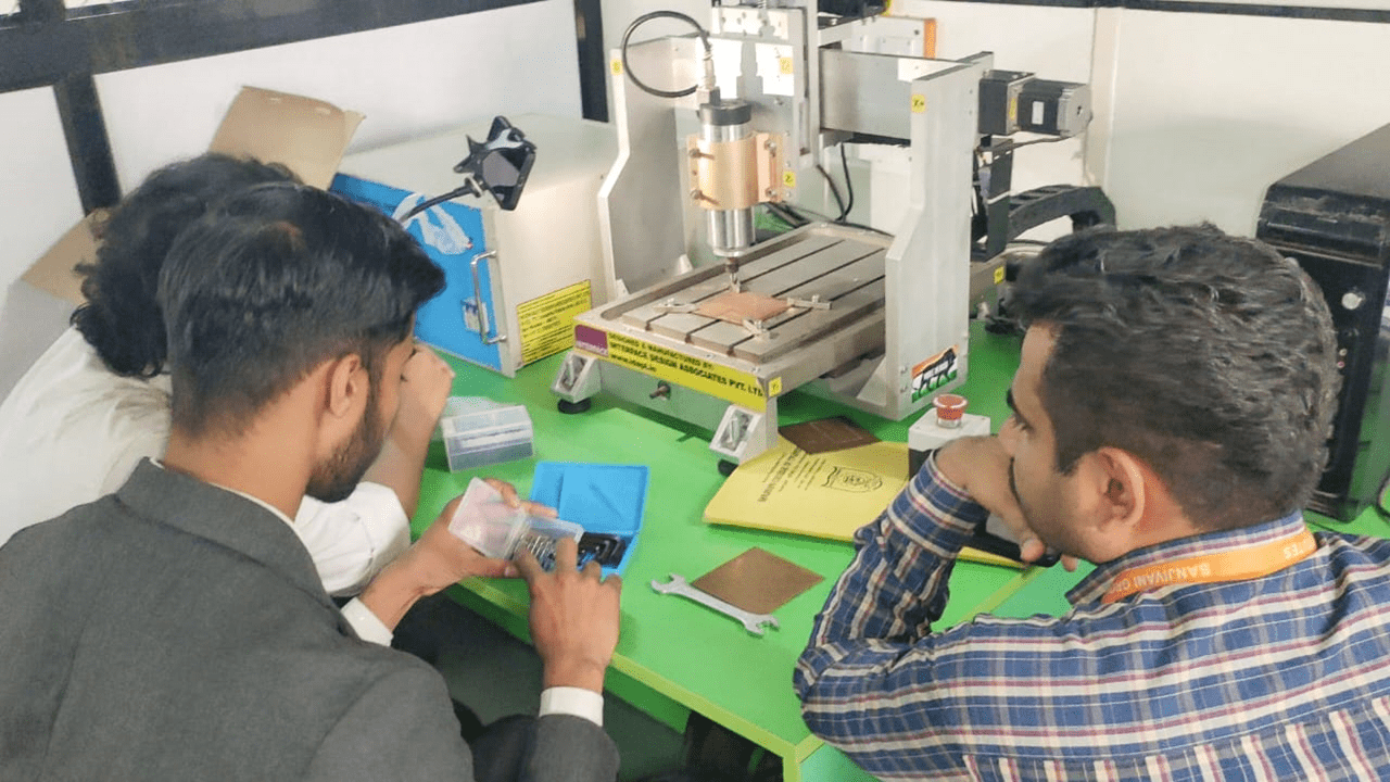
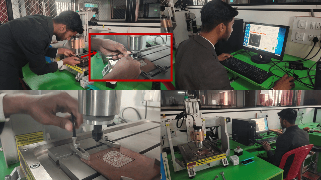
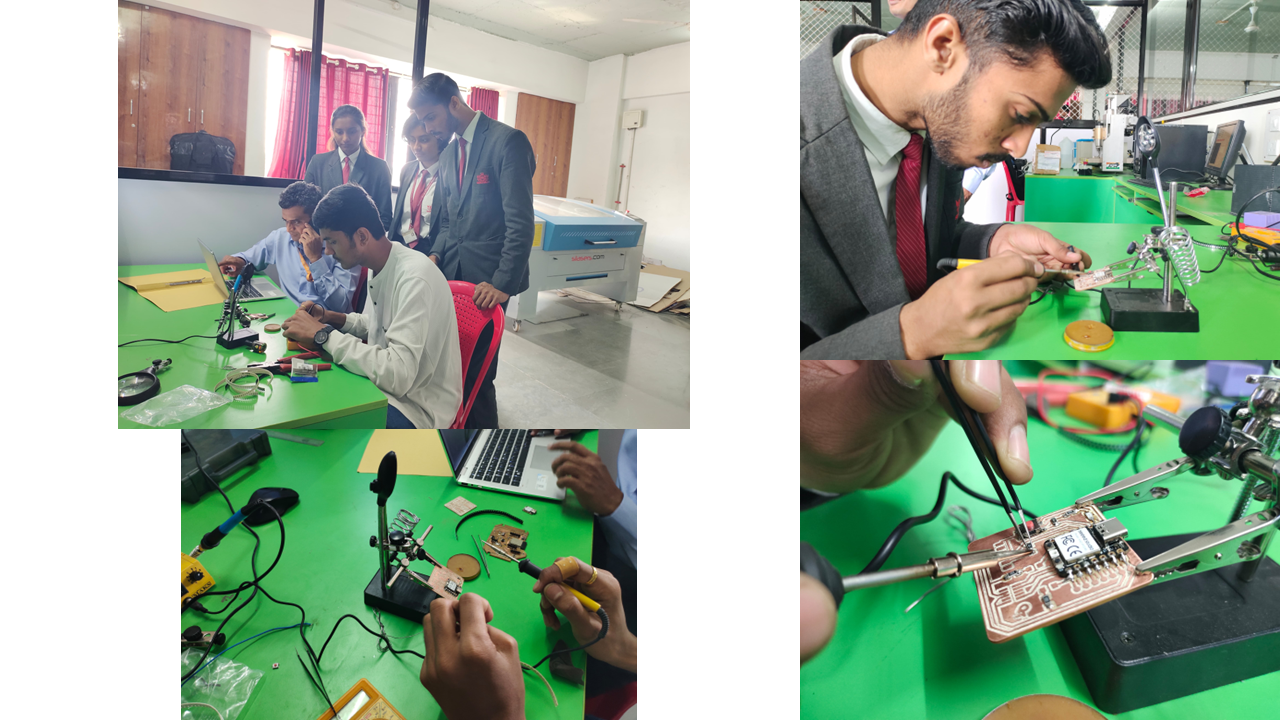
These are my hero shots of this week from the Dr. Kiran Wakchaure sir taken the lecture to the making pcb for characterization of machine
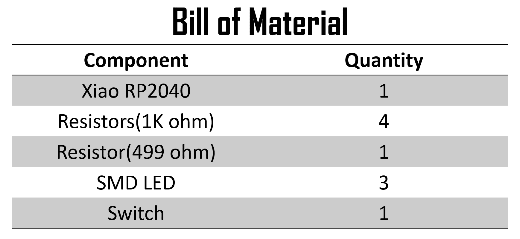
This is the board which I designed this week as part of the assignment. In this phase, I will be soldering the SMD (Surface Mount Devices) components onto it.
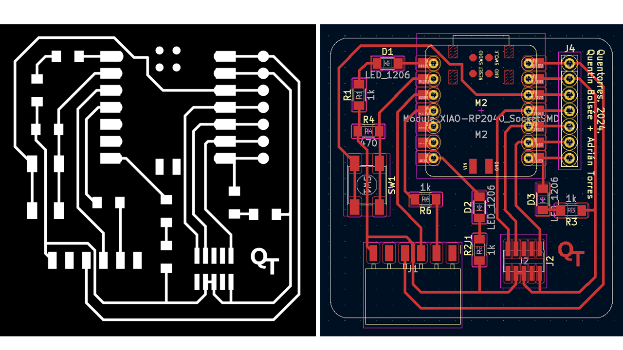
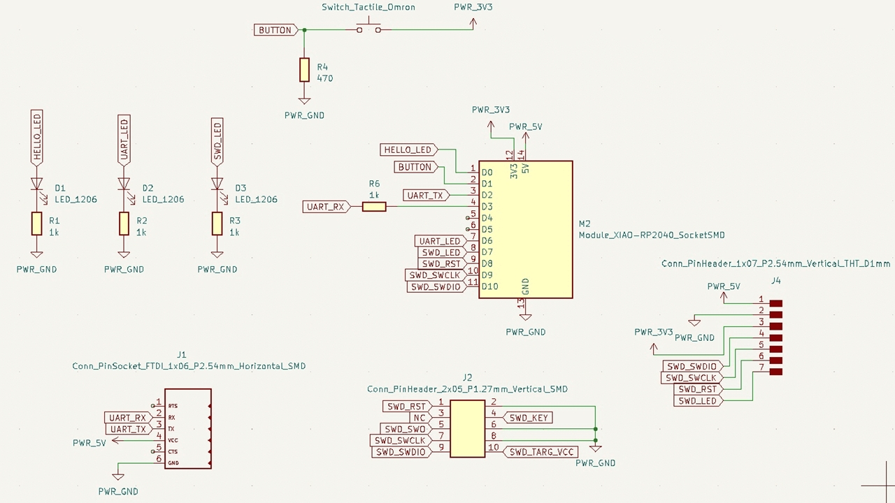
The board has an integrated LED and a button. With them you can learn to program. The LED is integrated on GPIO Pin 26 and the button is on GPIO Pin 27.
I completed the soldering of the SMD components, and it was very enjoyable for me. In my first attempt, I soldered them properly and successfully.
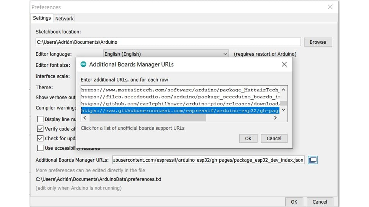
In File->Preferences, we will add the URL of the additional boards that you can find here. We need the Arduino-Pico by Earlephilhower.
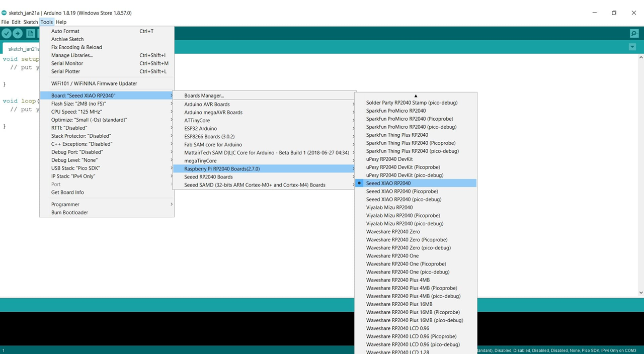
The next step is to download Pico in the boards manager. Tools->Board->Board manager
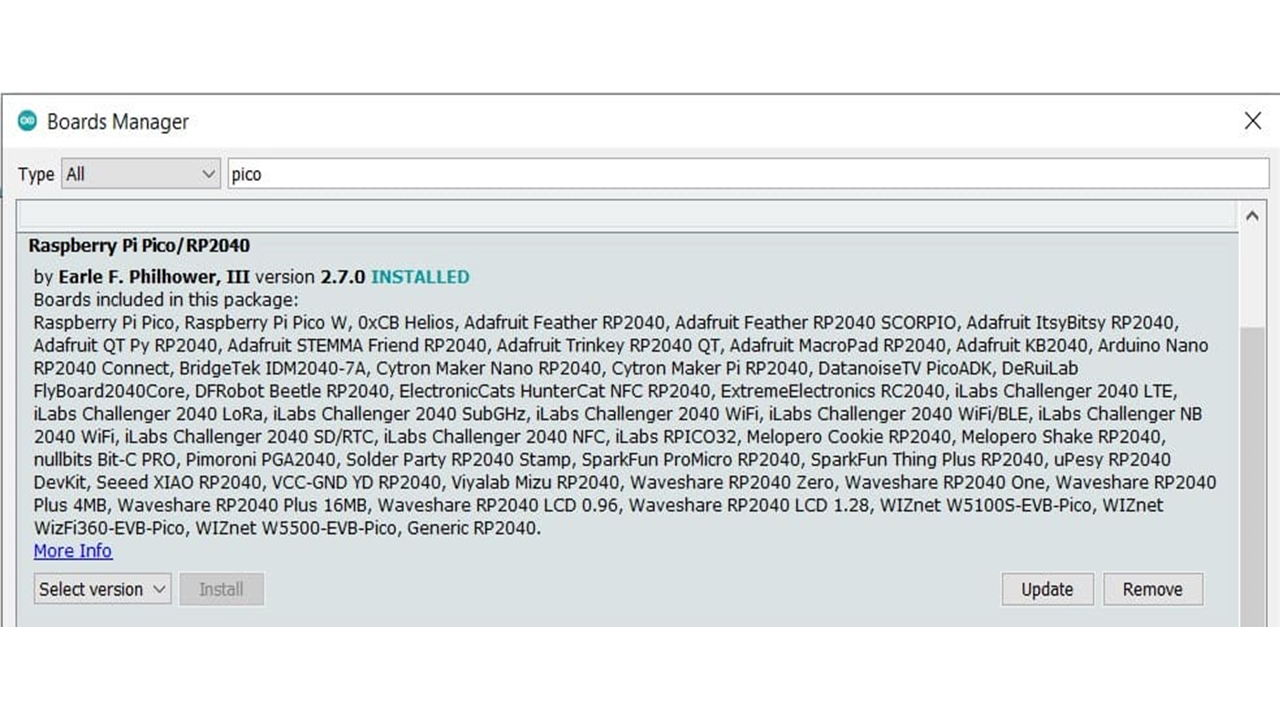
We configure the Arduino IDE for the Seeed Studio XIAO RP2040. The Seeed Studio XIAO RP2040 will appear in the COM port, in my case in COM 3.
I programmed the board to blink all the LEDs, and I also utilized the push button to toggle the LEDs on or off.
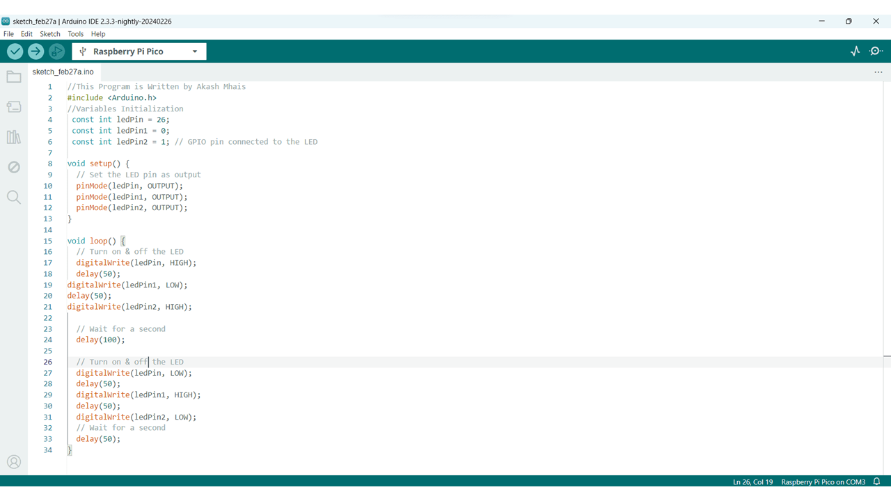
These are some programs that i have used on my board
//This Program is Written by Akash Mhais

        #include

        //Variables Initialization

         const int ledPin = 26;

         const int ledPin1 = 0;

         const int ledPin2 = 1; // GPIO pin connected to the LED


        void setup() {

          // Set the LED pin as output

          pinMode(ledPin, OUTPUT);

          pinMode(ledPin1, OUTPUT);

          pinMode(ledPin2, OUTPUT);

        }


        void loop() {

          // Turn on & off the LED

          digitalWrite(ledPin, HIGH);

          delay(50);

        digitalWrite(ledPin1, LOW);

        delay(50);

        digitalWrite(ledPin2, HIGH);


          // Wait for a second

          delay(100);


          // Turn on & off the LED

          digitalWrite(ledPin, LOW);

          delay(50);

          digitalWrite(ledPin1, HIGH);

          delay(50);

          digitalWrite(ledPin2, LOW);

          // Wait for a second

          delay(50);

        }
            //This Program is Written by Akash Mhais

            #include


            const int ledPin = 26;

            const int ledPin1 = 0;

            const int ledPin2 = 1; // GPIO pin connected to the LED


           void setup() {

             // Set the LED pin as output

             pinMode(ledPin, OUTPUT);

             pinMode(ledPin1, OUTPUT);

             pinMode(ledPin2, OUTPUT);

           }


           void loop() {

             // Turn on the LED

             digitalWrite(ledPin, HIGH);

           digitalWrite(ledPin1, HIGH);

           digitalWrite(ledPin2, HIGH);


             // Wait for a second

             delay(1000);


             // Turn off the LED

             digitalWrite(ledPin, LOW);

             digitalWrite(ledPin1, LOW);

             digitalWrite(ledPin2, LOW);

             // Wait for a second

             delay(1000);

           }
                //This Program is Written by Akash Mhais

                #include


                    const int redLedPin = 0;

                    const int greenLedPin = 1;

                    const int blueLedPin = 26;

                    const int buttonPin = 27; // Replace with the actual button pin if different


                    int buttonState = LOW; // Initial button state

                    bool ledOn = false;   // Flag to track LED state


                    void setup() {

                      // Set LED pins as outputs

                      pinMode(redLedPin, OUTPUT);

                      pinMode(greenLedPin, OUTPUT);

                      pinMode(blueLedPin, OUTPUT);


                      // Set button pin as input with internal pull-up resistor

                      pinMode(buttonPin, INPUT_PULLUP);


                      // Initially turn off LEDs

                      digitalWrite(redLedPin, LOW);

                      digitalWrite(greenLedPin, LOW);

                      digitalWrite(blueLedPin, LOW);

                    }


                    void loop() {

                      // Read the button state

                      buttonState = digitalRead(buttonPin);


                      // Toggle LED state on button press (rising edge)

                      if (buttonState == LOW && !ledOn) {

                        ledOn = true;

                        digitalWrite(redLedPin, HIGH);

                        digitalWrite(greenLedPin, HIGH);

                        digitalWrite(blueLedPin, HIGH);

                      } else if (buttonState == HIGH && ledOn) {

                        ledOn = false;

                        digitalWrite(redLedPin, LOW);

                        digitalWrite(greenLedPin, LOW);

                        digitalWrite(blueLedPin, LOW);

                      }

                    }
After the tool change, I forgot to set the Z parameter to the bed level, which resulted in damage to the tool.
Whenever we change the tool, handle it carefully because it is costly. After the tool change, reset the Z parameter because the length of the tool may vary, potentially causing damage to the tool or PCB.
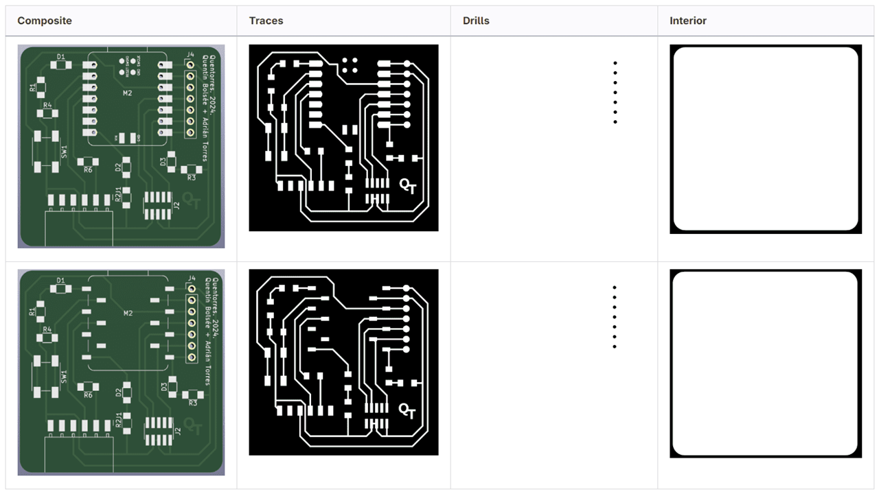
1. quentorres_traces.png file
2. quentorres_interior.png file
3. Raspberry Pi Pico Library
4. Traces G-code.
5. Interior G-code.