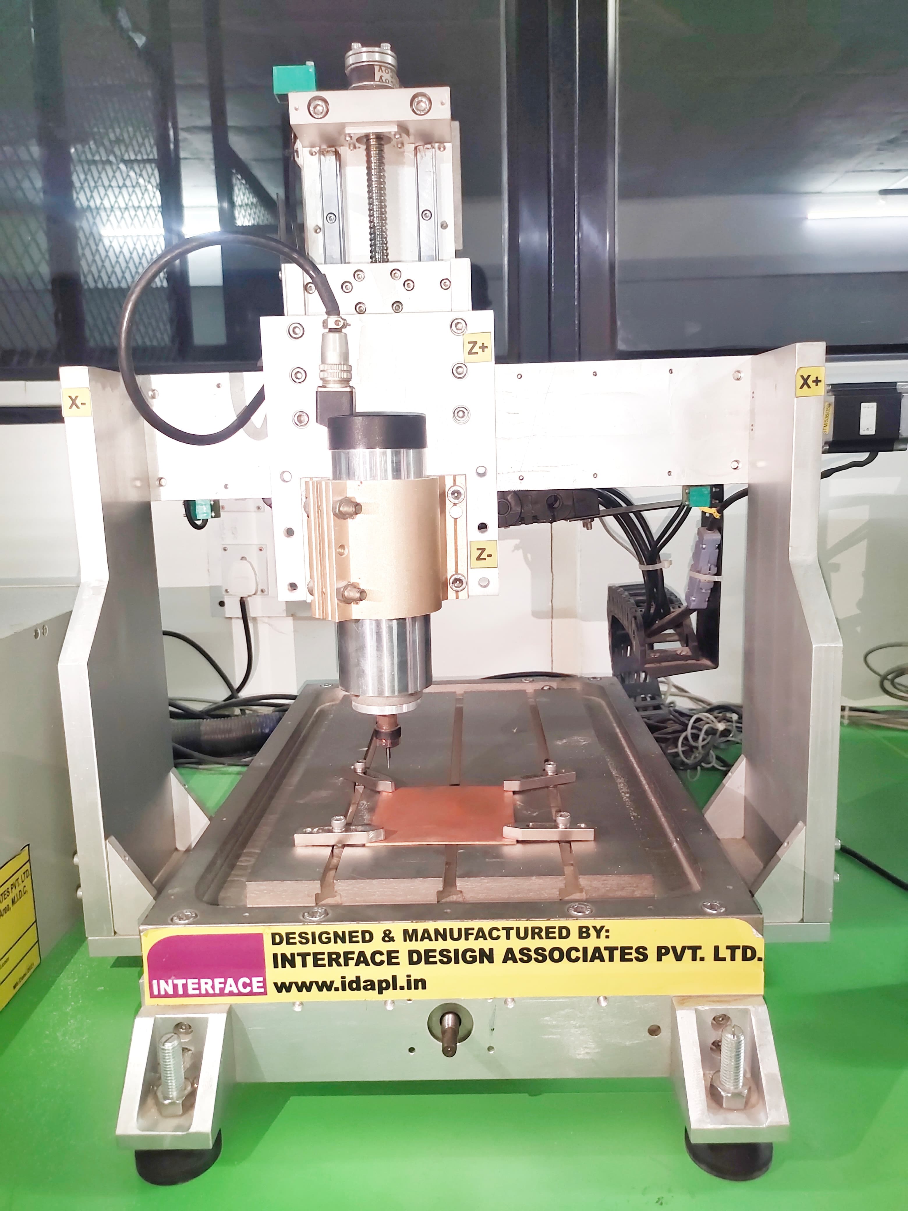
In this assignment, we are going to characterize the design rules for a PCB milling machine and utilize the milling process for PCB fabrication.
The manufacturer of the machine is Interface Design Associates Pvt. Ltd., a local manufacturer in India.
Additionally, we are utilizing the WinMill,
which combines the power of the SC06 with a user-friendly application running under the Windows 7/8/8.1/10 32-bit system.
The SC06 card is a three axis CNC controller which is highly cost effective controller
with following features:
• 4 Axis of digital numerical control
• G & M Code support
• Multiple Operation Modes.
• Manual Mode - Jog, Incremental, Absolute and Home.
• PLC Interface available
• 16 digital inputs and 16 digital outputs. (Additional RemIOV4 card with serial port
comm.)
The CNC controller is a standard PC running Microsoft Windows 7. The motion is
controlled through the SC06 card and the IOs are through an intelligent IO board
(SC04 BOB ISO ). The PLC system forms a part of the CNC application and the PLC
ladder logic program and the GCODE programs are coordinated.
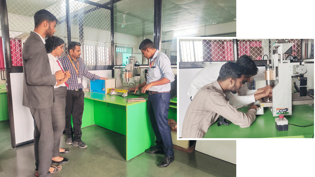
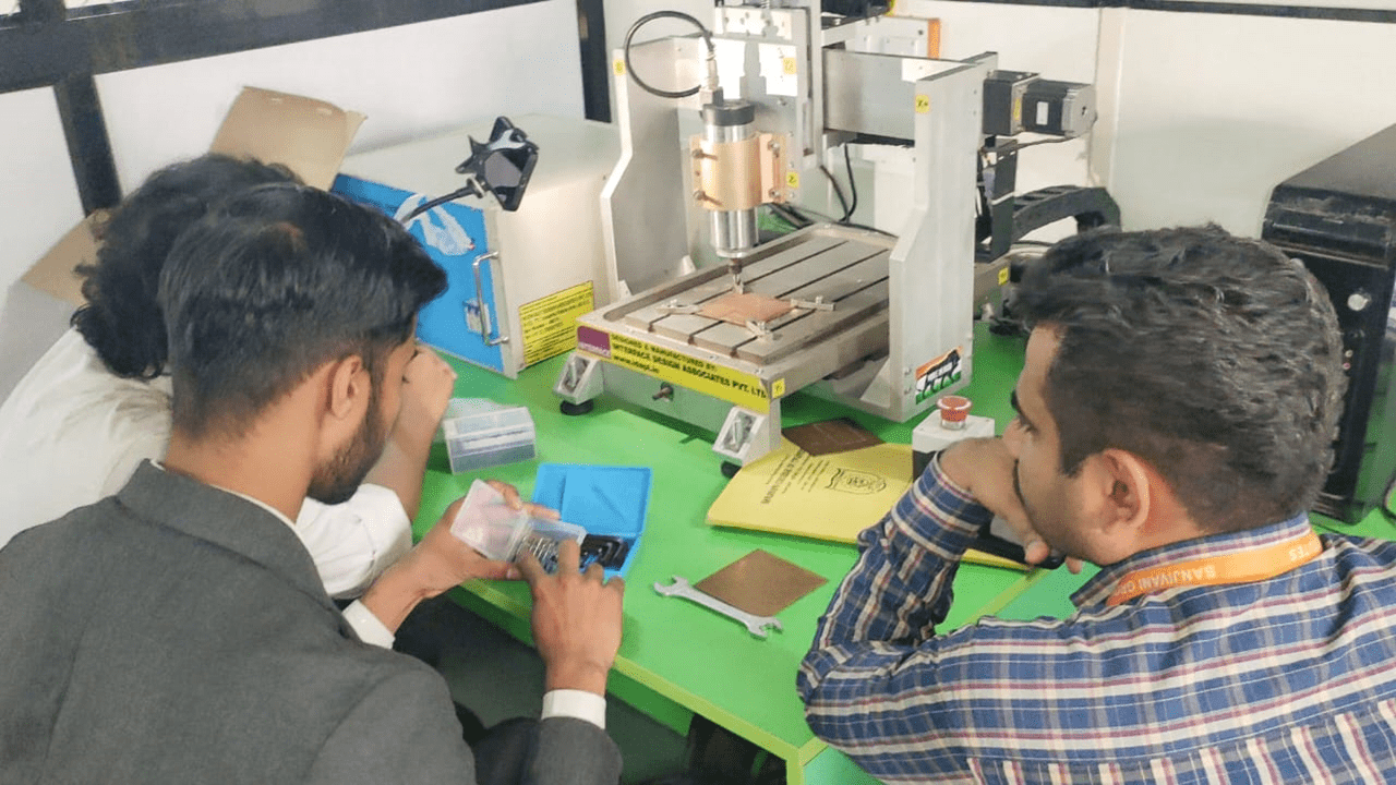
Our local instructor, Dr. Kiran Wakchaure, gave a lecture about the PCB milling machine, then i fix the tool into the spindle properly
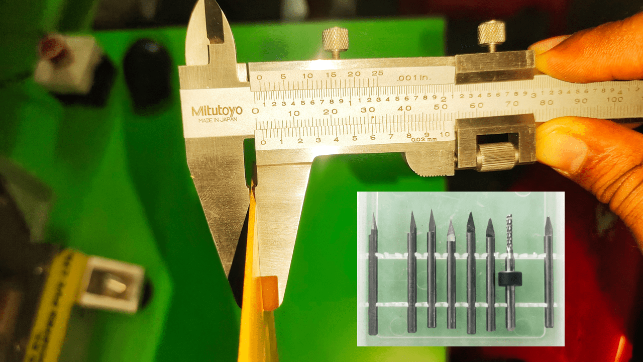
I measured the thickness of the sheet to determine and set the maximum depth of the tool.
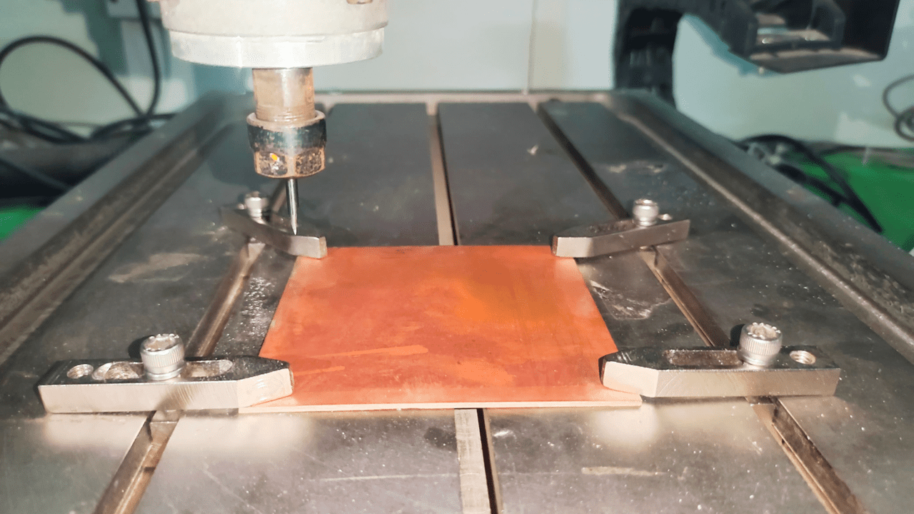
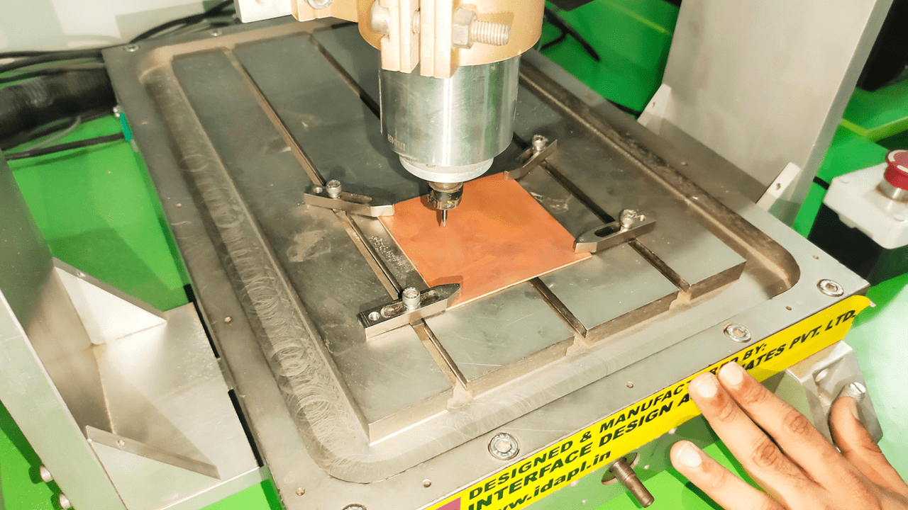
I fixed the sheet using clamps on the workbench, which is a crucial step. Uneven fixing of the material can result in incorrect traces, potentially leading to defects in the PCB.
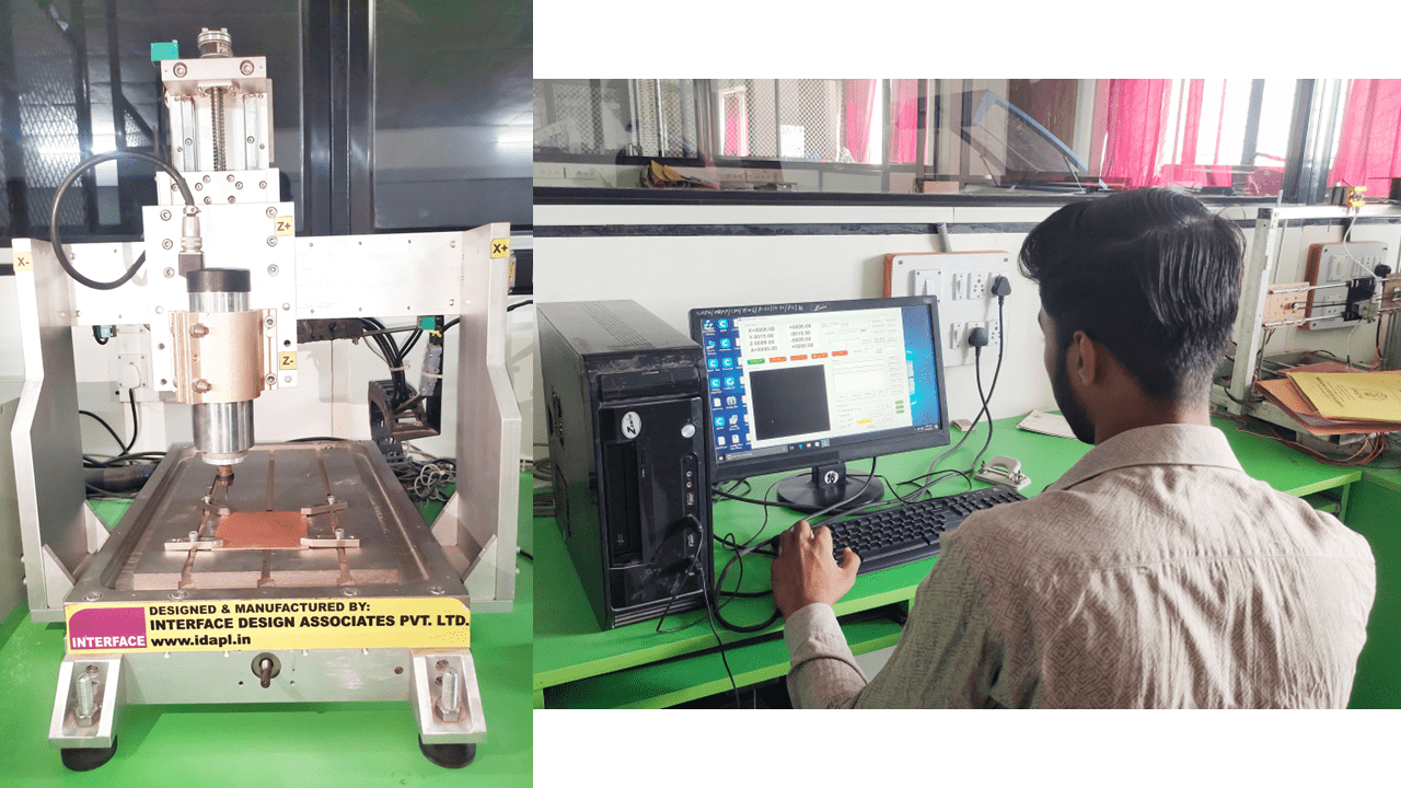
Then, I loaded the program into the software and properly set the X, Y, and Z coordinates.
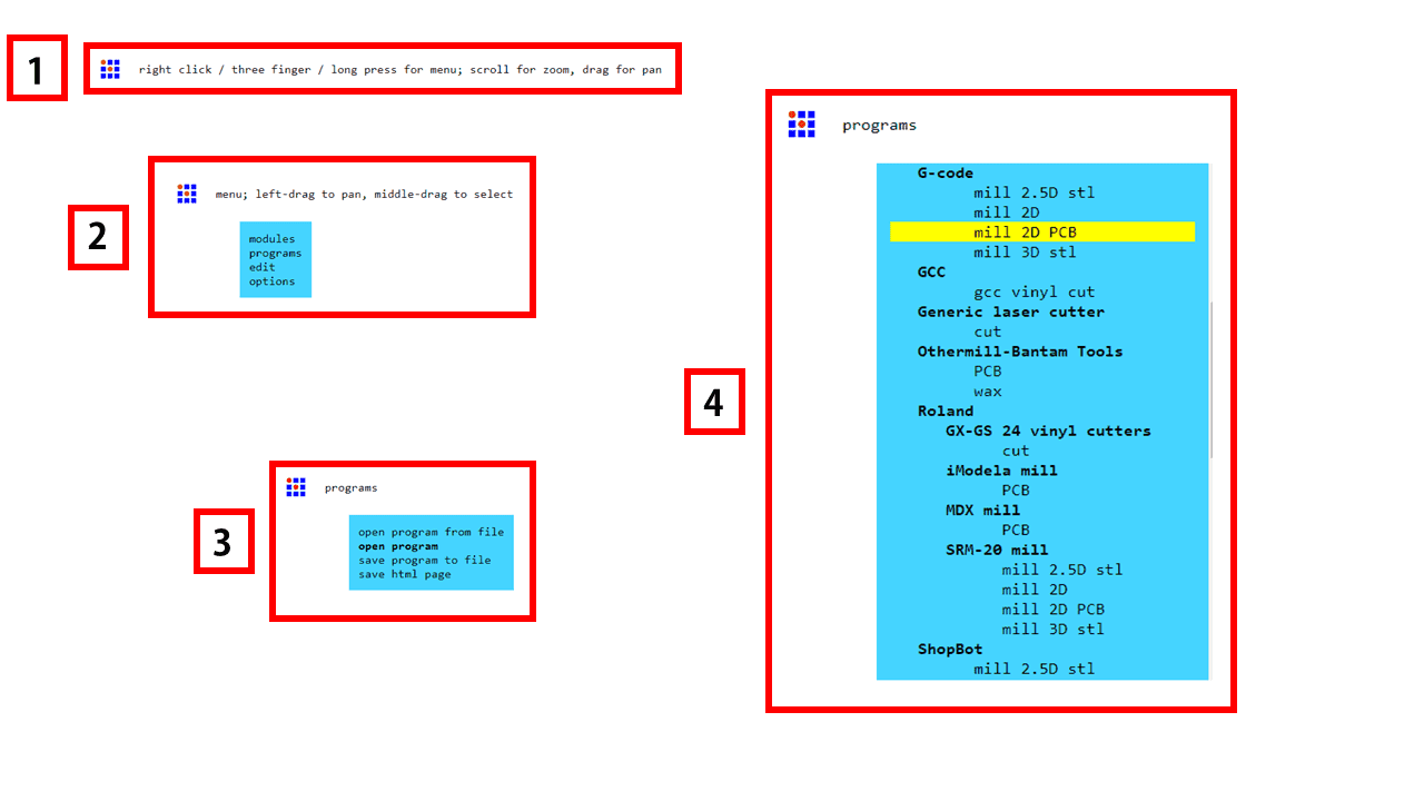
We used the modules for generating the G-code for the machine. For this, I followed the following process: firstly, right-click on the blank page to open the next tab, where we get modules, programs, edit, and options. From there, select the programs option. Then, in the next tab, select the "mill 2D PCB" option, and the program will open.
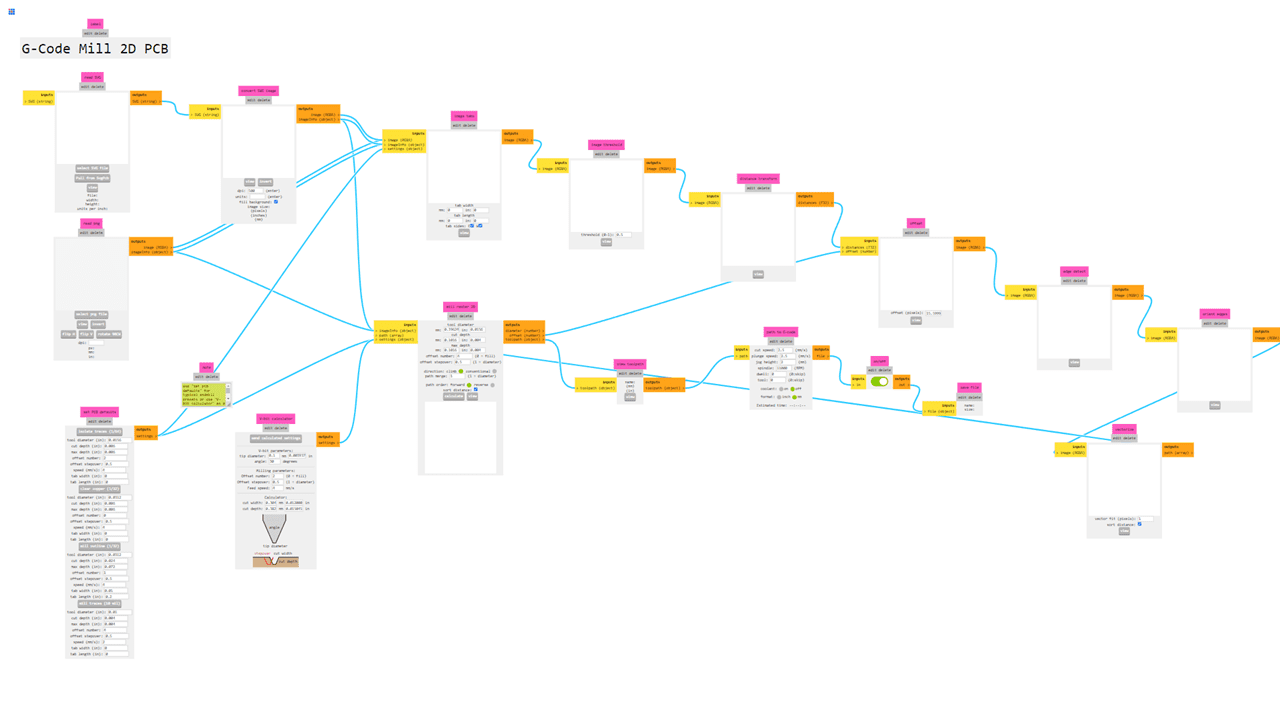
This is the interface of the program, and it is a little bit different from other software, but it is simple to use.
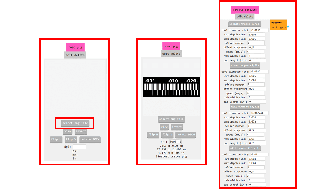
In this program, we can import two types of file formats: .svg and .png. In our case, we will be using the .png file format. After opening the file, go to "Set PCB Defaults" and select the mill outline (1/32).
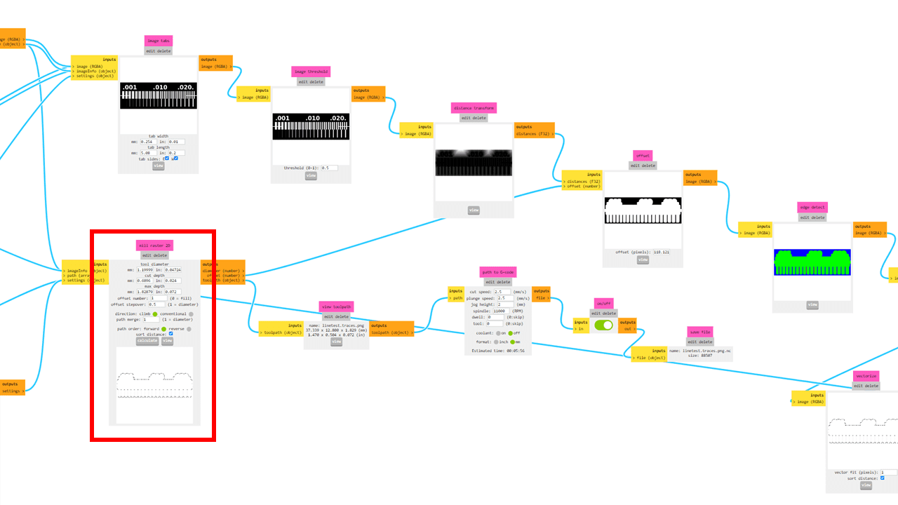
After selecting the mill outline (1/32), proceed to "Mill Raster 2D." Here, we can adjust the tool diameter, cut depth, and the maximum depth of the tool. Then, click on the "Calculate" option. The code file will be downloaded, and we can view the traces by clicking on the "View" button.
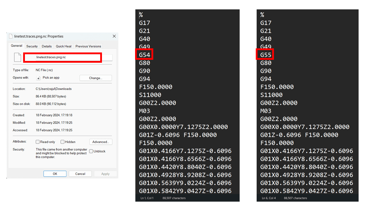
The downloaded file is in the format of .nc. In our case, we have to change the extension of the file from .nc to .gcd for compatibility with our software and the machine. Additionally, we edit the file and make some changes in the G-code, such as changing from G54 to G55.
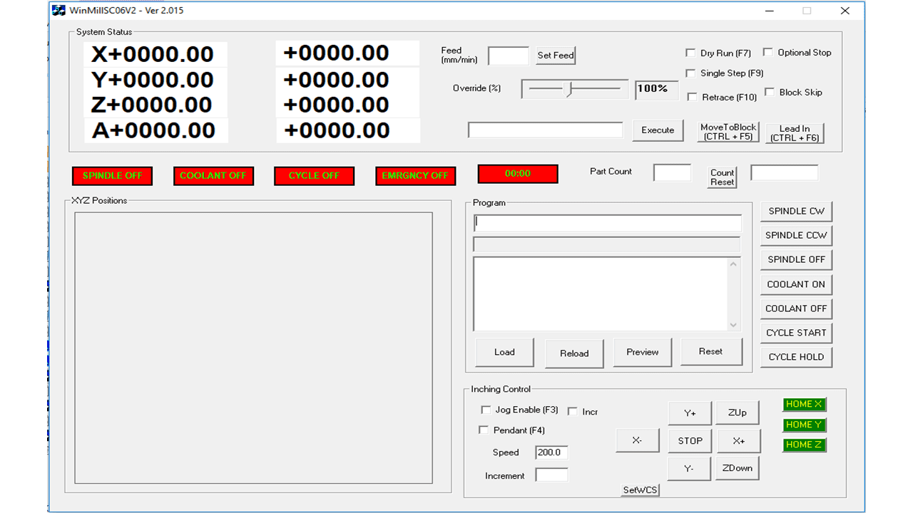
This is the interface of the software used for the PCB milling machine, which is provided by the local manufacturer of our fab lab's PCB milling machine.
The information displayed is:
1. Idle mode of the machine displayed
2. Machine status consisting of the following parameter is displayed:
X, Y, Z and A axis co-ordinates
Feed rate, Override, Dry run, Single step, Retrace, Optional Stop, Block Skip
Spindle ON/OFF and Coolant ON/OFF
Cycle Start and Cycle Hold
Load, Reload, Preview and Reset And Jog control section.
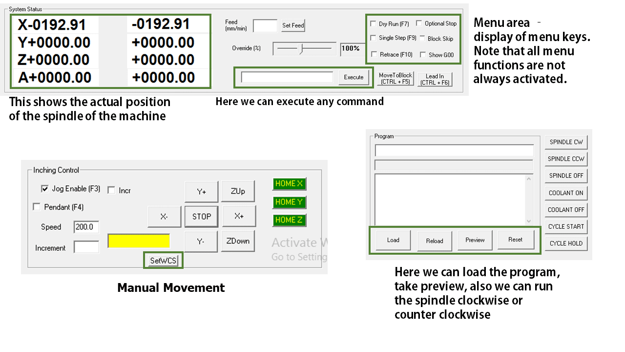
Manual Movement: Manual movement is provided as a sub menu of play menu. Click on Jog Enable on
the play screen to enter into the jog menu.
There are three options for Jogging:
1. Jog Enable: Once Jog Enable is selected, the mechanism moves in the direction specified by
pressing the buttons X+, X-, Y+, Y-, ZUp or ZDown. The movement stops only
when the STOP button is pressed. The speed of movement is the speed specified in
the Speed option in mm/min. The default speed is 200 mm/min.
2. Incremental: When incremental motion is selected, the mechanism will move with the specified
speed only for the distance specified in the Increment option.
SYSTEM STATUS MENU: It displays the current displacements in the X, Y and Z dialog box while running cycle. In another dialog box shows the remaining displacement while running cycle. The another "Feed (mm/min)" dialog box is used to set Feed rate if user call the codes as micro variable, the system will move with set feed rate. The "Override (%)" dialog box is used to set override speed while running cycle, user can select manually the override feed by adjusting control bar. Options for selecting to run cycle as Dry run by selecting Check box "Dry Run(F7)". If user select this option the only X axis and Y axis movement will happen, the Z axis movement will not consider. This dry run option is useful for verification of newly generated g-code. The another check box for "Single Step (F9)" is used to run cycle in single step mode. If user select the Single Step check box and execute, the system will executes current block of G-code by indicating the command block in "Execute" dialog box. Once first command execution get done, it ready to execute next block which will pop up in "Execute" dialog box. The "MoveToBlock(CTRL + F5)" is used to skip g-code block which are ready to execute.
CONTROL MENU: The Control Menu is used to control Inputs & outputs like Spindle ON/OFF, Coolant ON/OFF, Cycle Start, Cycle Hold. User can turn ON the Spindle by using buttons "SPINDLE CW" for clockwise direction and "SPINDLE CCW" for counter clockwise direction, to Turn OFF the Spindle press "SPINDLE OFF" button. Similarly for Coolant ON/OFF press "COOLANT ON"/"COOLANT OFF". For Cycle starts and Cycle hold use "CYCLE START" and "CYCLE HOLD" buttons.
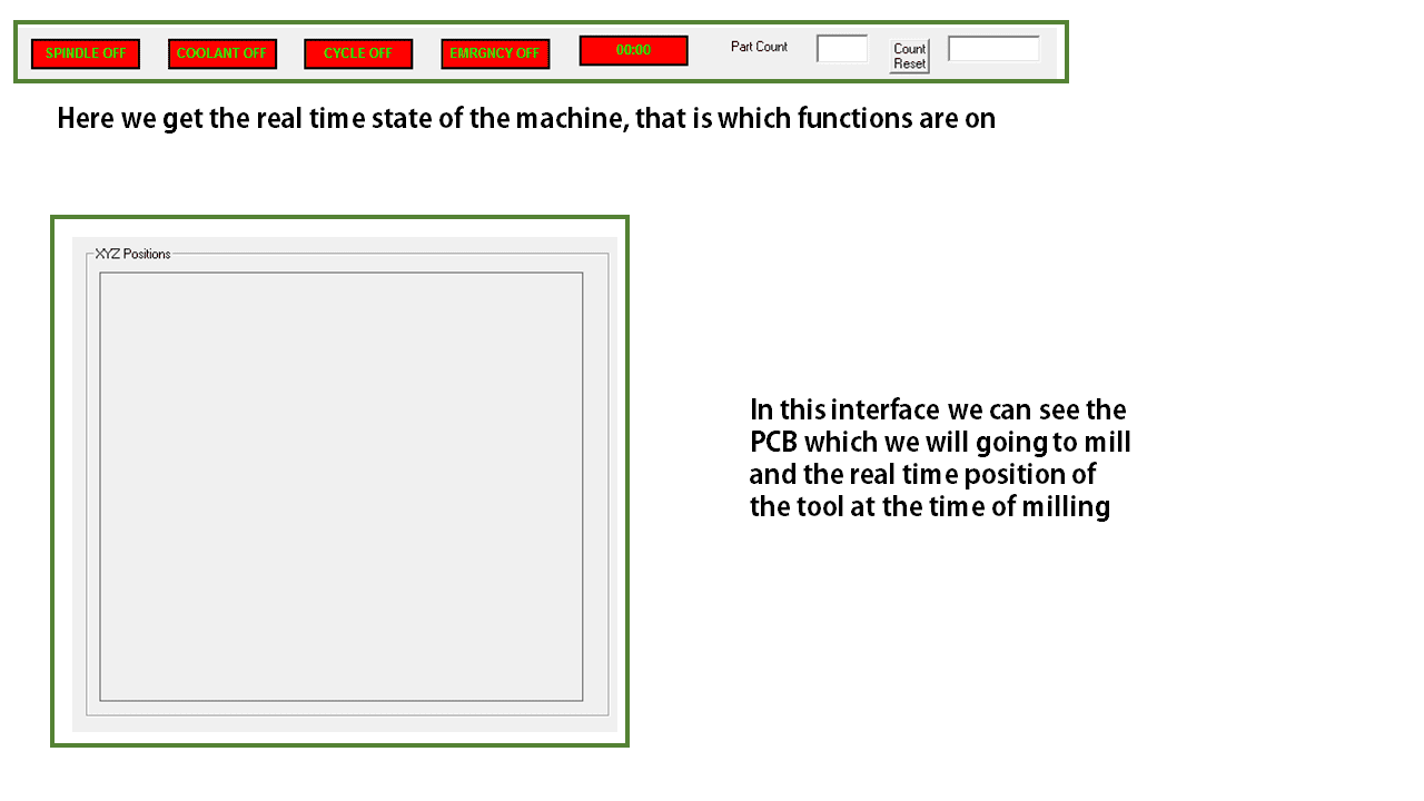
Indication Window: In indication window it will indicates the status of Spindle, Coolant, Cycle ON/OFF, Emergency ON/OFF, Cycle time. For OFF condition it will indicate in Red colour for respective status tab and for ON condition it will indicates in Green colour. In "Part Count" dialog box it will show cycle counts, the count will increment after completing every cycle. To reset part counts use "Count Reset" button.
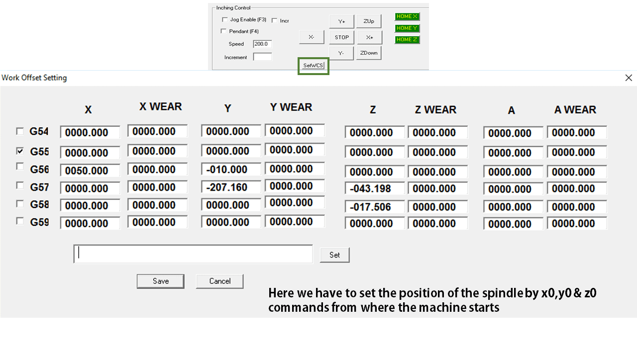
This is Work Offset setting in which we can set the co ordinates of the spindle
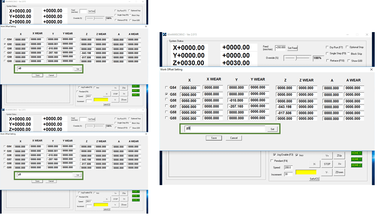
Enter X0 then click set button. Repeat the same for other axes. After setting the values click on save button to save those values.
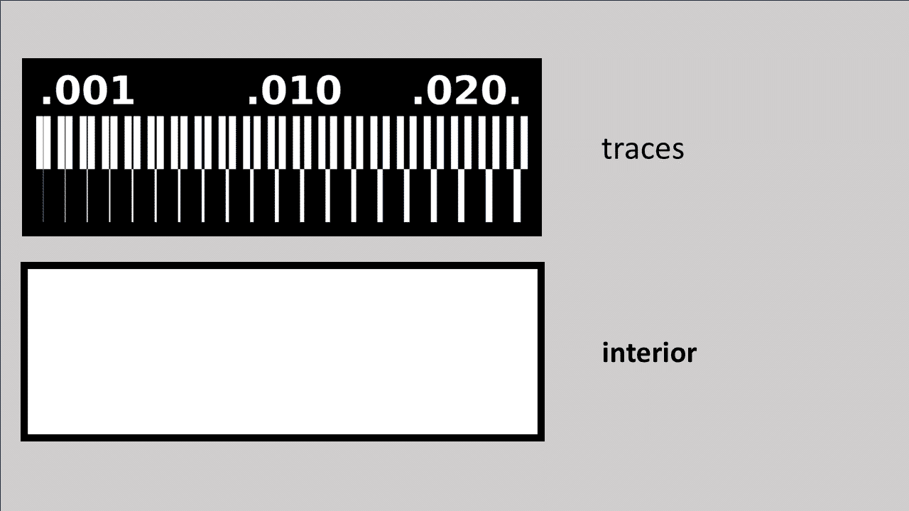
We have downloded these files from the electronic production week page for the Characterization of our PCB milling machine
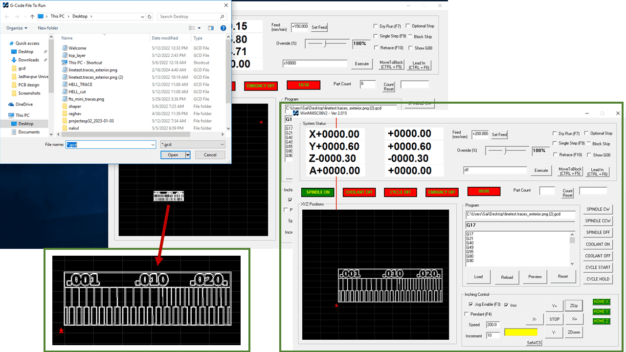
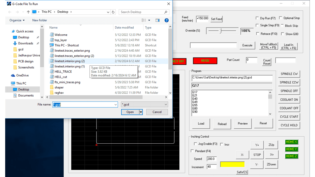
I used the 'load' button to import the file into the software. Then, I conducted a dry run of my PCB to properly understand how much material and space are being utilized for this PCB.
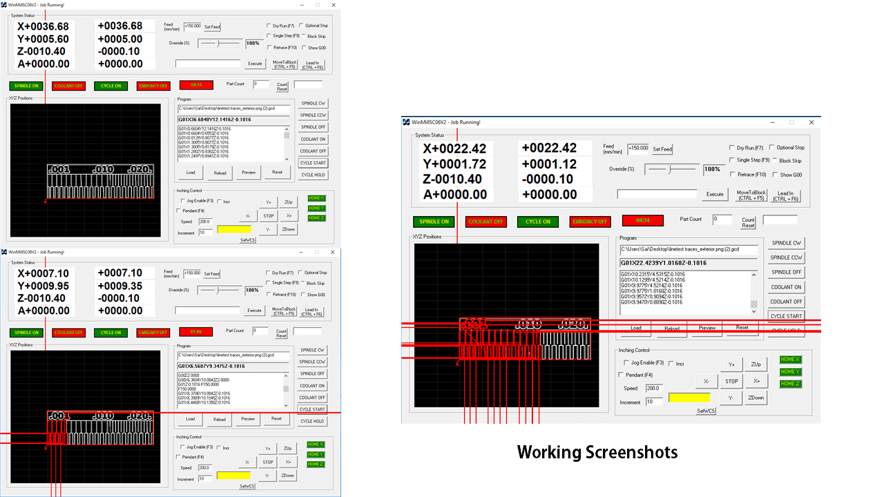
On the display, it will show the toolspath of the real-time operation of the machine. However, there is a software bug causing the path to extend beyond the window.
Then, I changed the tool for cutting the interior of the PCB and clicked the reset button to reset the program. Afterward, I used the load button again to load the program for the interior and cut the outline of the PCB.
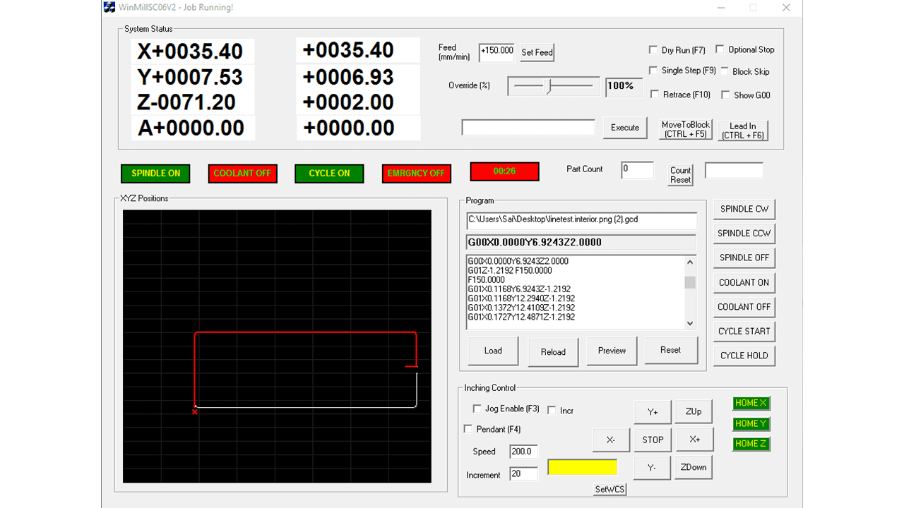
again it will display the toolpath of the spindle of the milling machine.
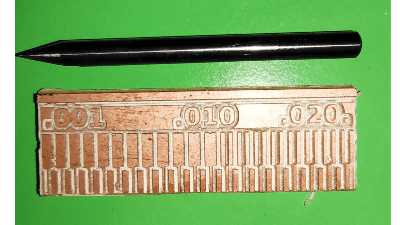
This is the output i got from the milling machine.