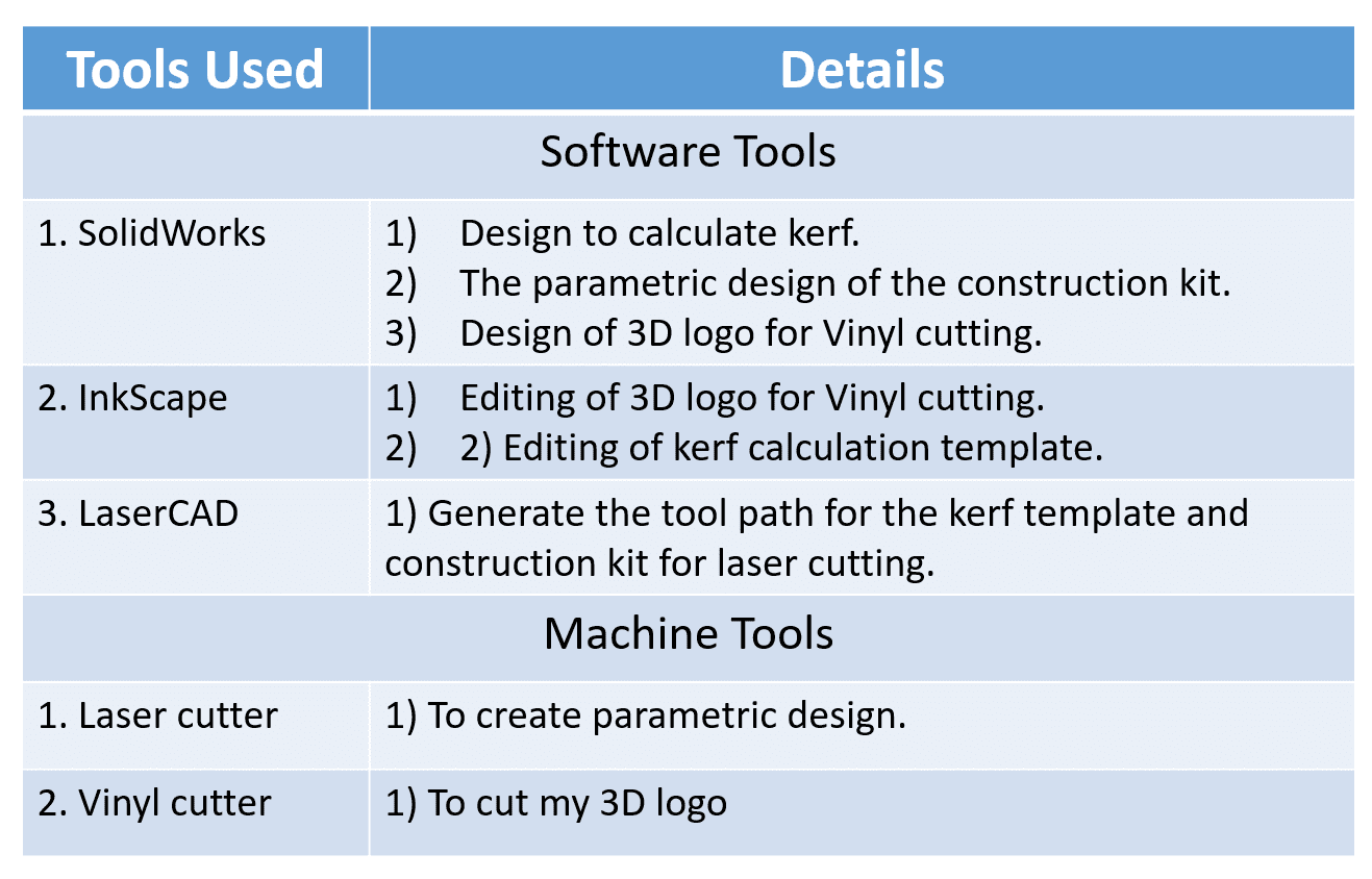
In this week, I am going to work with two very interesting machines: a laser cutting machine and a vinyl cutting machine. During this time, I will be focusing on the characterization of the laser cutter and parametric modeling. Additionally, I plan to cut some materials using the vinyl cutter.
Characterization of Laser Cutter - Power, Speed, Clearance, Kerf, Focus.
You can find group assignment here
1. Using Vinyl Cutter Making cut something
2. Design, laser-cut, and document a parametric construction kit,
taking into consideration the laser cutter kerf, that can be assembled in multiple ways.
In this portion of the assignment, I utilized a Vinyl Cutter Machine (VCM) that operates within a voltage range of 85 to 264 volts and requires a current of 1 ampere to cut specific shapes from vinyl material.
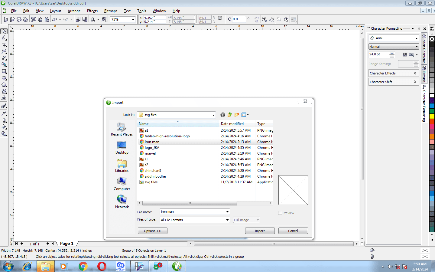
I used the software CorelDRAW to edit the logo, which I downloaded from the internet. I simply imported the image into the software using CTRL + I or by selecting the import option.
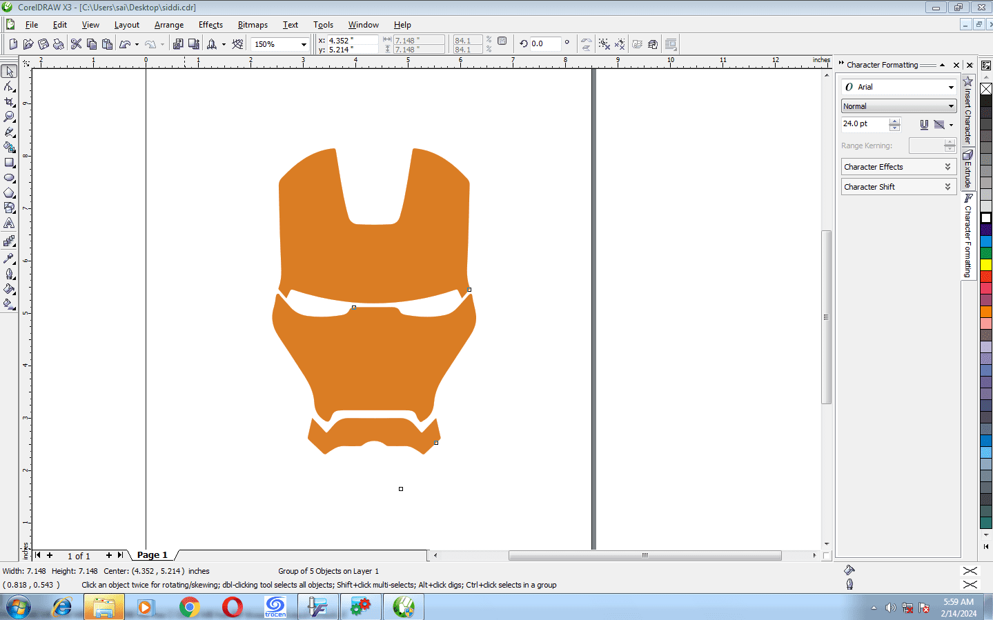
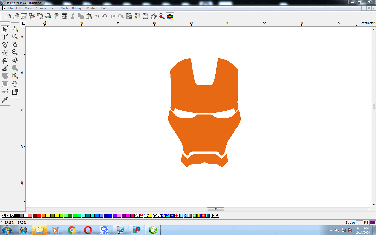
I have imported the image of Iron Man for cutting.
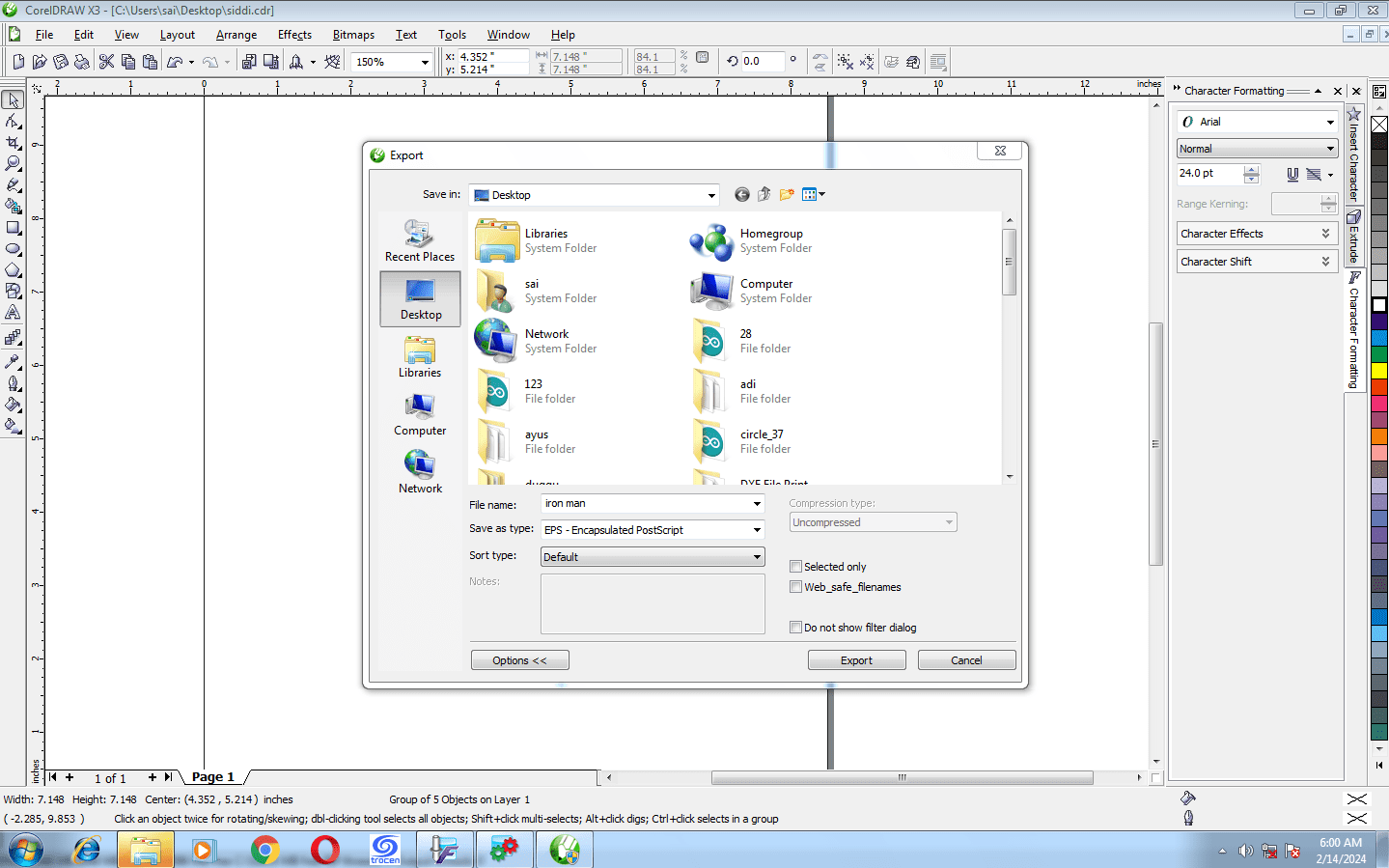
Then I saved that image as EPS (Encapsulated PostScript) format, which is a favorable format for FlexiSign software.
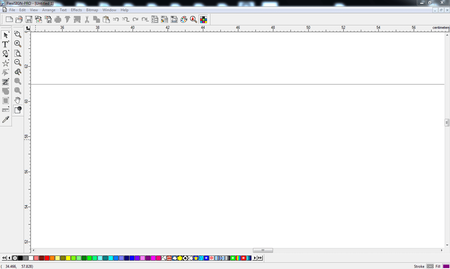
This is the interface of the FlexiSign Software. There are many options available, such as importing images, saving, exporting, cutting, adding text, adjusting colors, and much more.
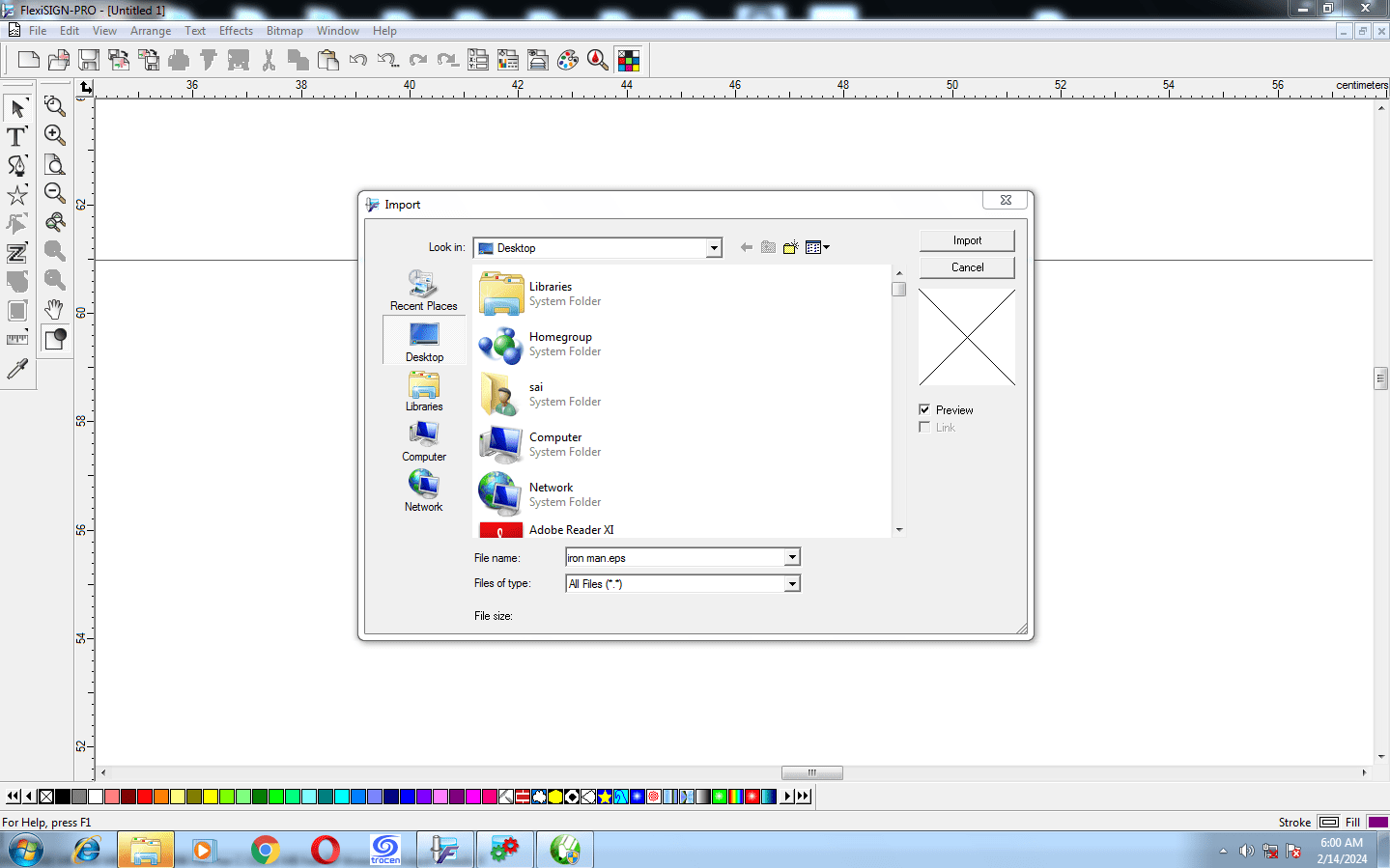
I imported the file of format .eps into FlexiSign Software.
the interface will look like this after the import of the file.
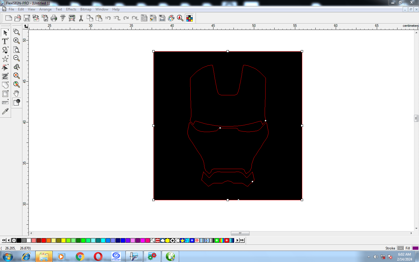
Then I Selected the Image and clicked on Cut/Plot option to cut it on vinyl cutter.
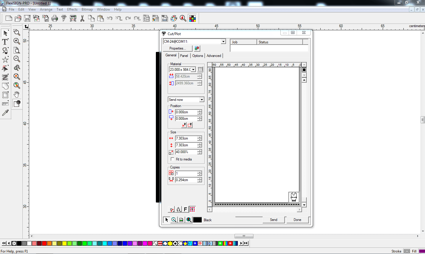
I set the Position as X - 0.00 and Y - 0.00 for cutting it from the corner as shown in image the image is moved to the right bottom corner. also I set the size as Height - 7.303 and Width - 7.303. after that i choosen the copies as 1 and by selecting the com port of the machine I sended the file to the vinyl cutter.
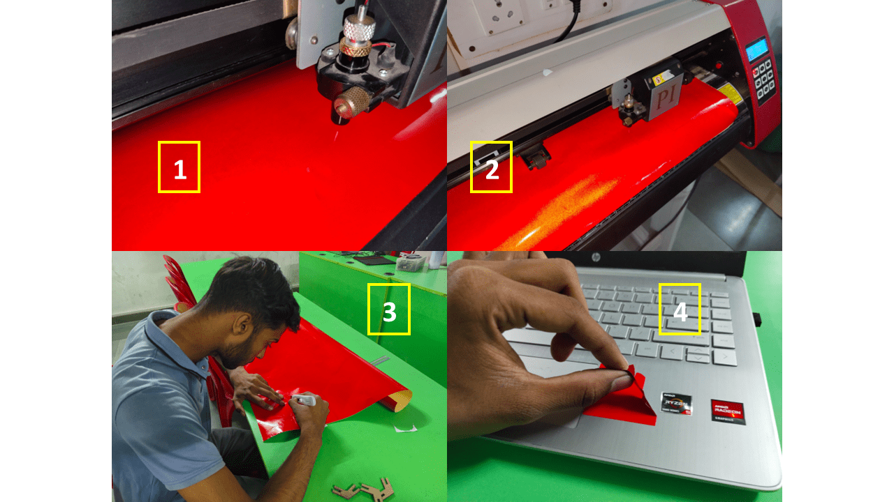
I Set the Origin and weight as 120gm and clicked on cut option to cut the logo.
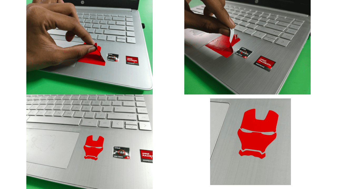
Then i stick the logo of iron man to my laptop, this will looks very nice.
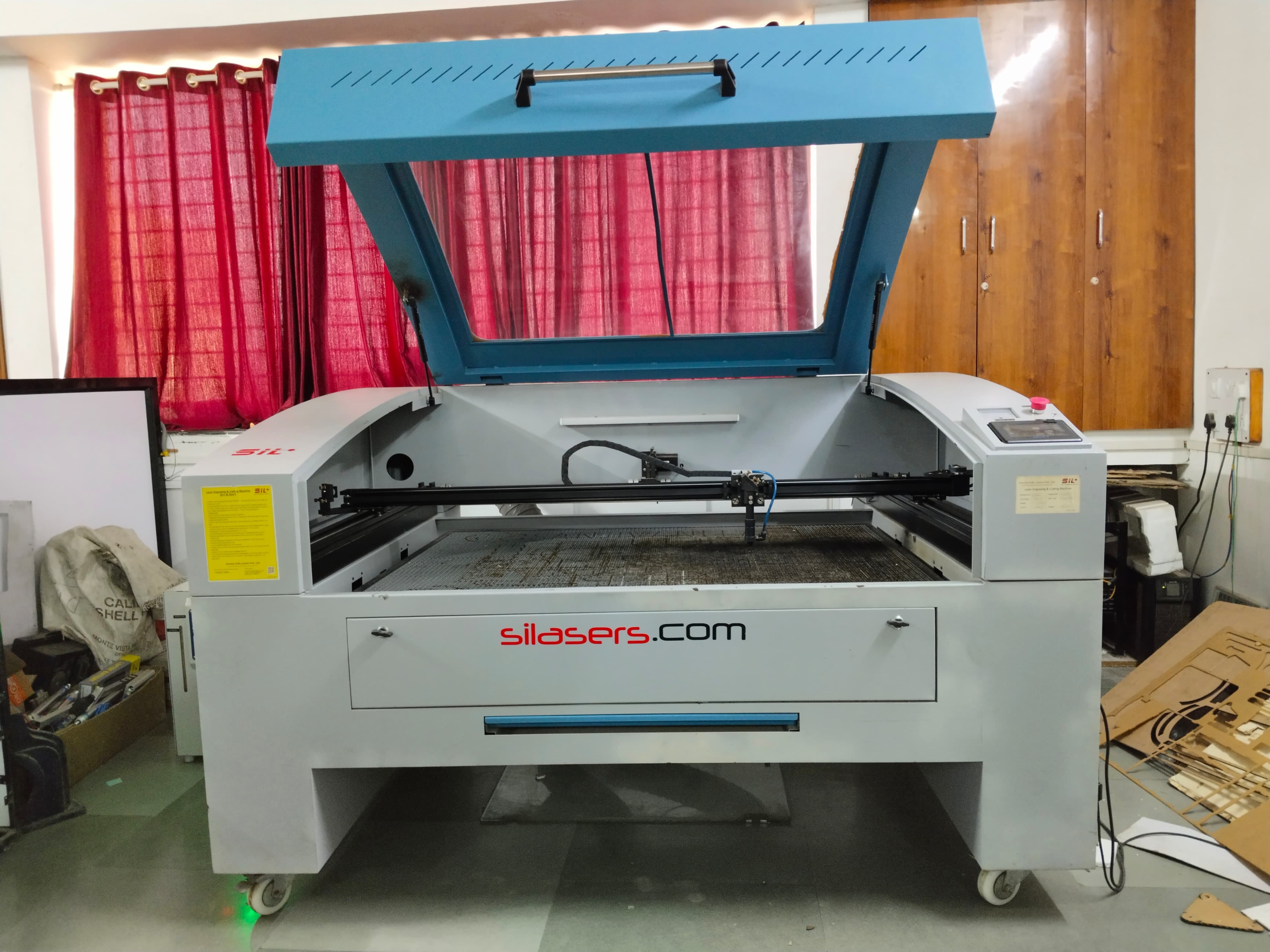
CO2 Laser Cutter is a powerful tool that uses carbon dioxide laser to cut and engrave a variety of materials with precision and accuracy. I works with various material like acrylic, leather, wood, paper, and many more. we can cut the 2D geometry in this Machine. A laser enables precise and efficient cutting of numerous materials in industry. Of the CO2 laser works with a carbon dioxide gas mixture And is one of the most powerful lasers. It was developed in the mid -1960s and convinced at the time with a high efficiency and comparatively low acquisition costs. Technology has been further improved in recent years. This gas laser is available in different designs and enables the setting of different power areas for different areas of application.
The CO2 laser has a wide range of applications, and nowadays, it is an emerging technology. Most of the applications are based on design and decoration.
1. Automotive Parts
2. Textile Industry
3. Prototyping
4. Decorative Parts
In a gas mixture of carbon dioxide, nitrogen and helium, which serves as an active medium, electromagnetic waves in the megahertz area are broadcast. The carbon dioxide molecules are stimulated and brought to a high level of energy. The energy is stored in these molecules as vibration or rotation. A continuously emitting carbon dioxide laser can be stimulated with a high voltage up to 20,000 volts and the resulting glow discharge. The stimulation of the molecules is possible with a high DC voltage or high-frequency change voltage. The carbon dioxide molecules have different forms of vibration with different energy levels. If an infrared photo meets an excited carbon dioxide molecule, energy is released as a photon. This process is called stimulating emission. The number of photons increases exponentially, If there are enough CO2 molecules. To achieve this, the emitted radiation between two mirrors is directed back and forth by the laser medium. A laser beam is created from the large number of photons, which enables precise cutting.
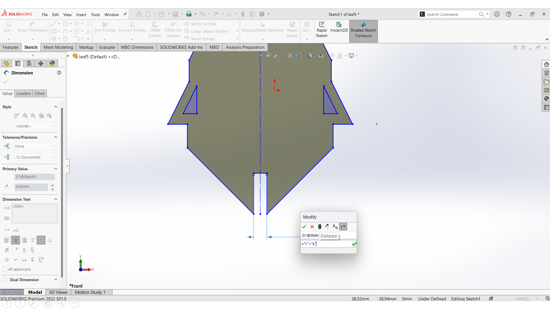
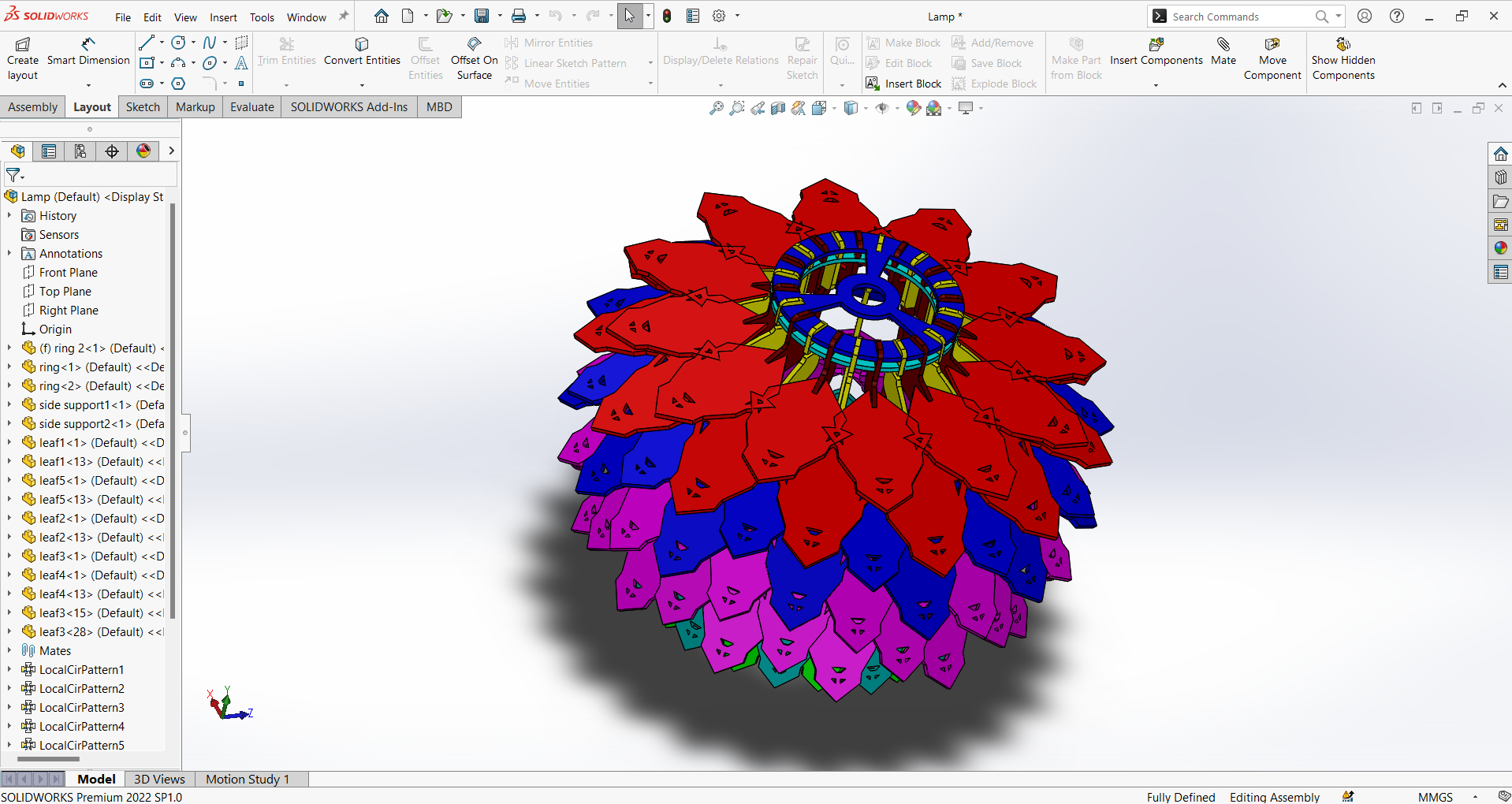
In this week, I decided to create a lamp using laser cutting technology. I began the design process in SolidWorks, where I created the lamp's components in 2D. For the lamp, I opted to use cardboard as the material with a thickness of approximately 4 mm. Consequently, all the slots in the design have been configured with a 5 mm width to accommodate the material.
Parametric Design in Solidworks:
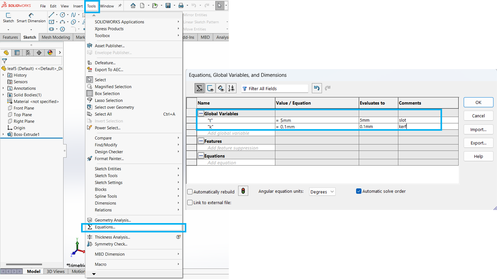
For Parametric Drawing we need to go in Tools --> Equations --> Global variable. here we have to assign variables along with the dimensions that we can change later on from here according to requirement, so i have added the thickness and kerf parameters as 5mm and 0.1mm respectively.
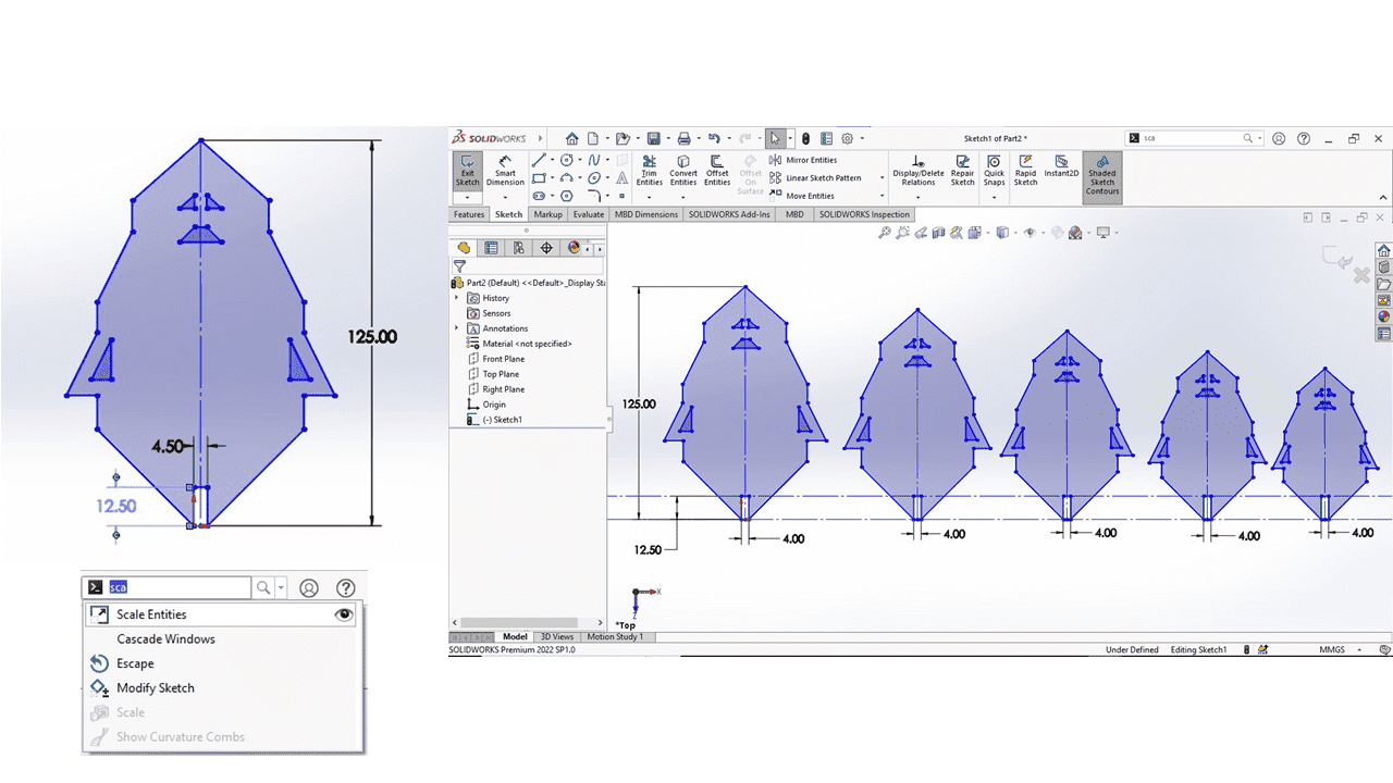
I have crafted the lamp's leaves by initially designing a single leaf. Subsequently, I employed the "scale entities" command to reduce the size of the leaf, and I replicated this process to create a total of five leaves.
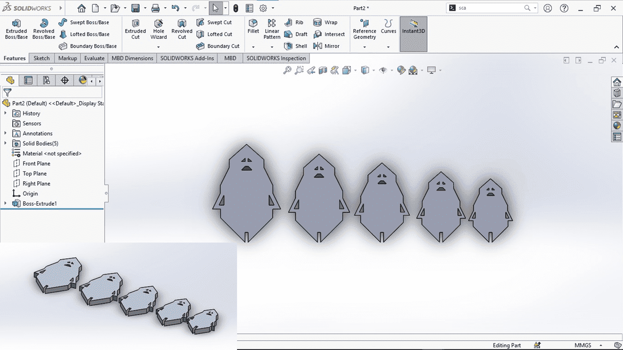
Afterward, I extruded the design to add thickness to the leaves, transforming them into a DXF file suitable for generating a 2D view of the object for laser cutting.
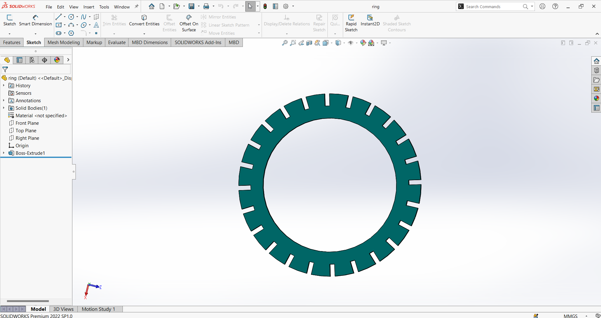
This is the Lower ring.
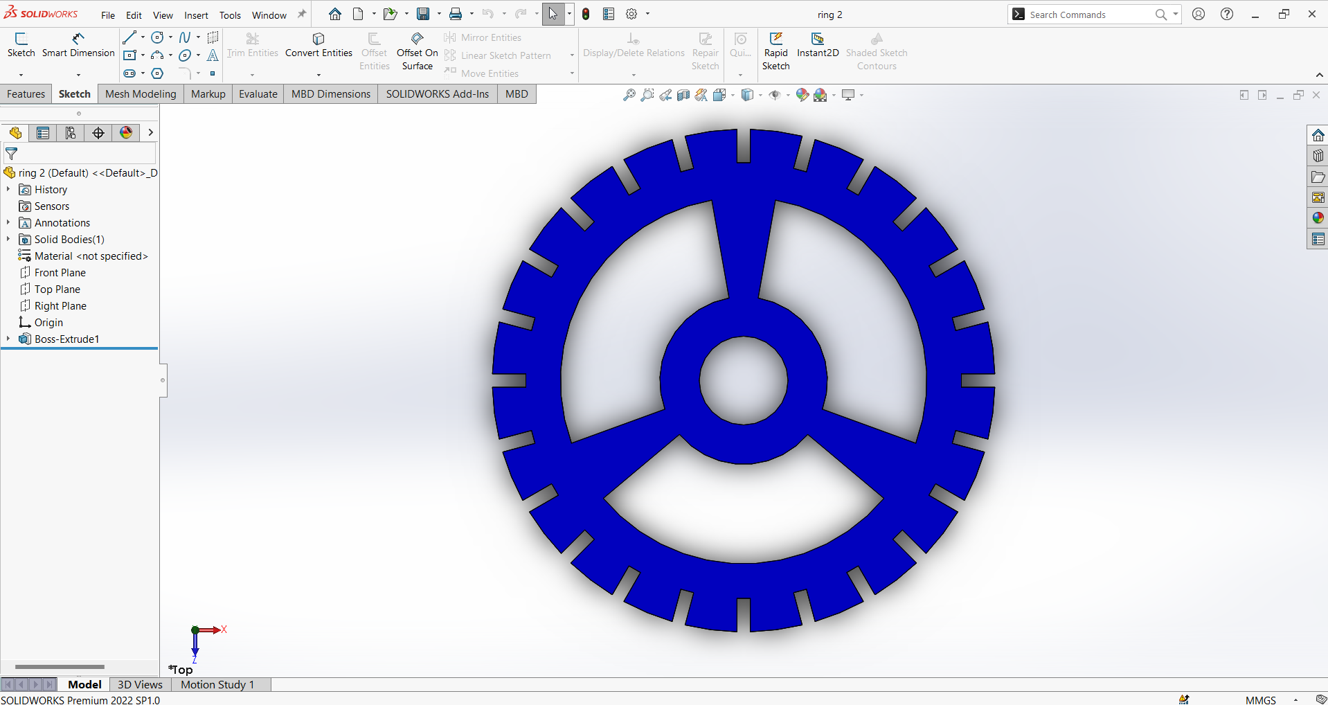
This is the upper ring of the lamp.
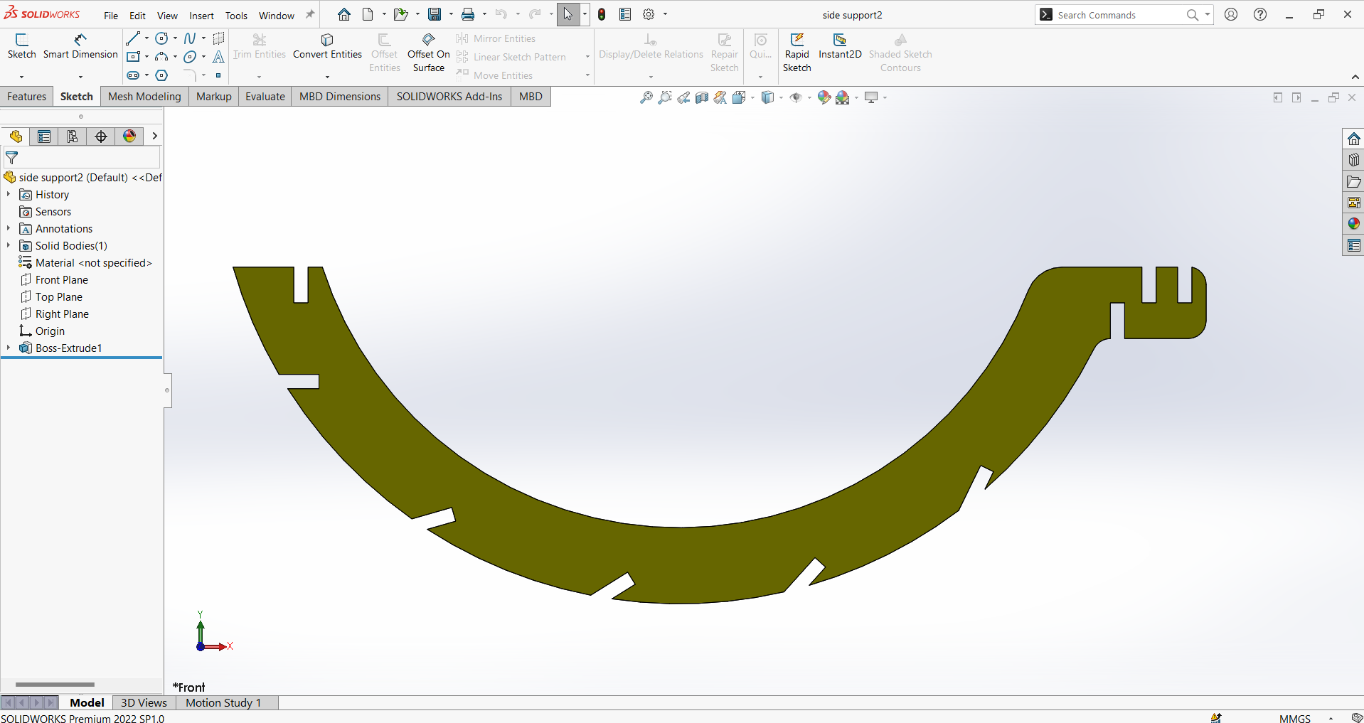
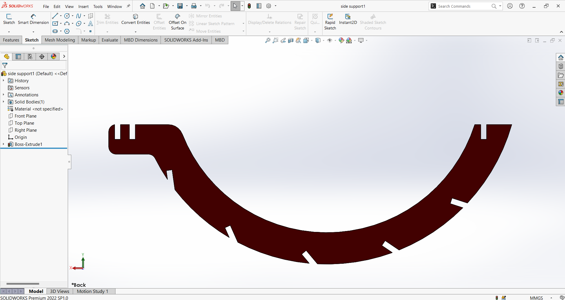
These are two types of side vertical supports.
This is whole assembly of the lamp.
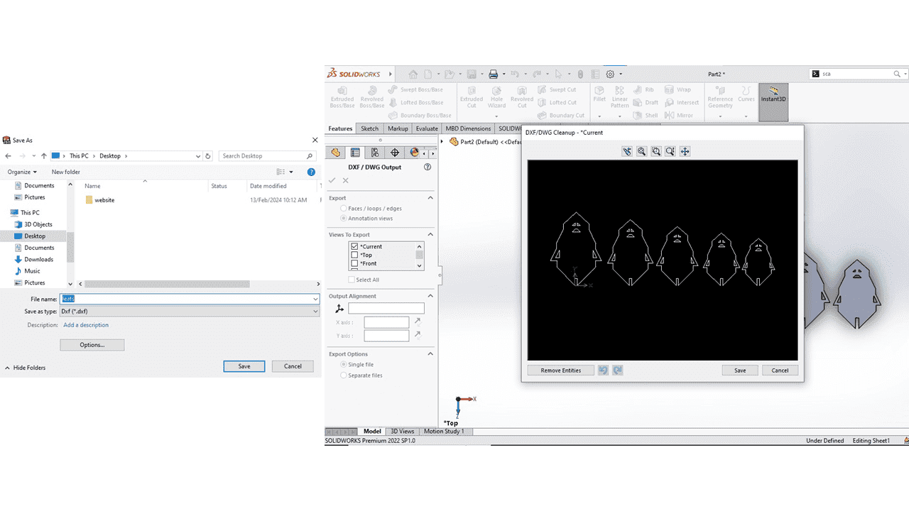
We can choose either the annotation view or the faces that need to be converted into the DXF file.
Laser Cutting Parameters:
Speed : 25
Power : 45
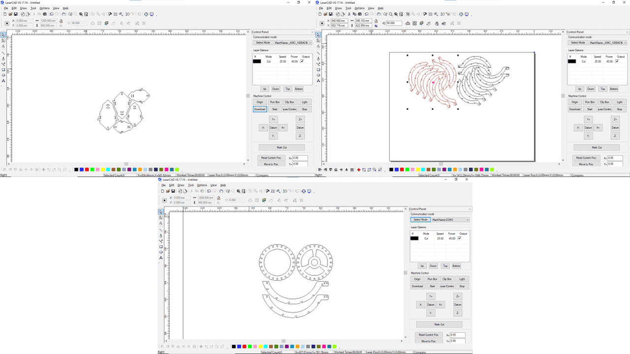
I imported the DXF file into LaserCAD software for laser cutting. You can use either the CTRL + I shortcut or the import option. After importing the file, I arranged the objects or geometries on the workspace. Then, I set the power and speed settings for the laser machine. Finally, I downloaded the file to the machine using a USB drive or a direct wired connection.
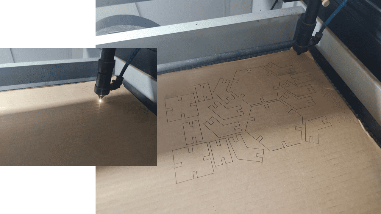
Then I sent the file to the laser cutter machine. I set the origin to the desired location for cutting my drawing. Finally, I clicked the "box" option to check the space required for cutting the drawing.
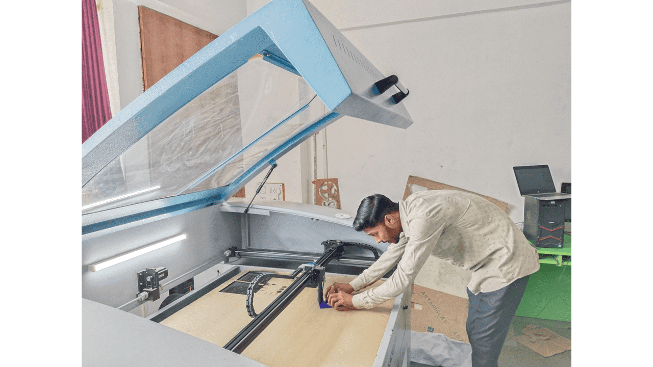
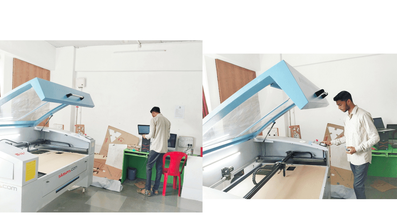
Next, I measured the distance between the nozzle and the material to ensure it was exactly 6mm. This is crucial for proper focus of the laser beam. If the distance is greater or less than 6mm, the beam will converge or diverge, respectively, leading to uneven cutting. Therefore, it's essential to maintain the precise 6mm distance for optimal results.
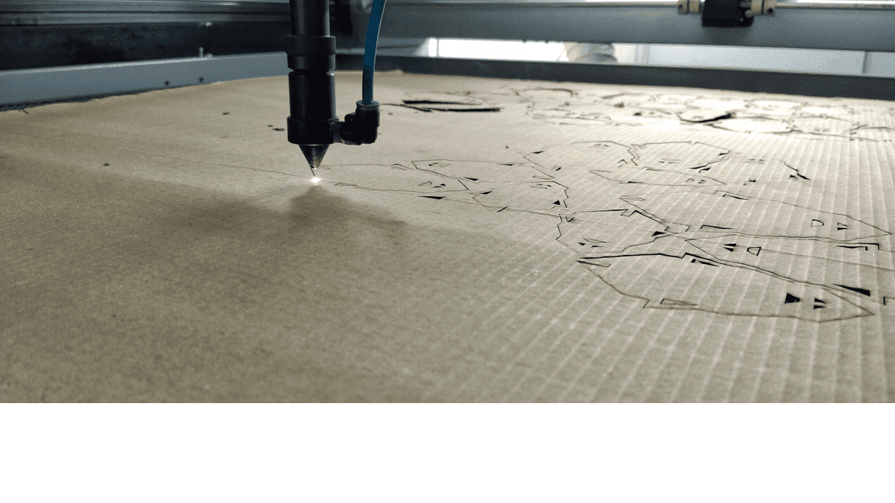
It was time to bring my lamp design to life. I hit the start button and watched the laser cut through the material, crafting the individual pieces.
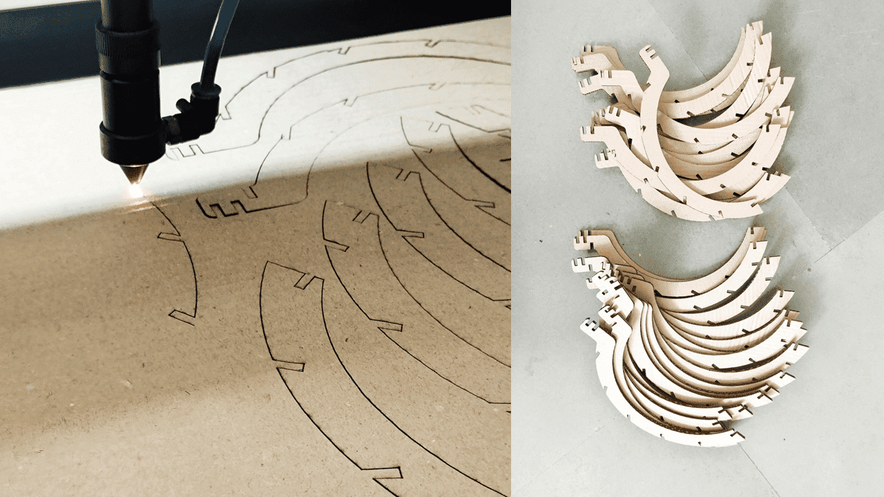
The laser cutter has done its job! Now it's time to assemble these parts into a lamp.
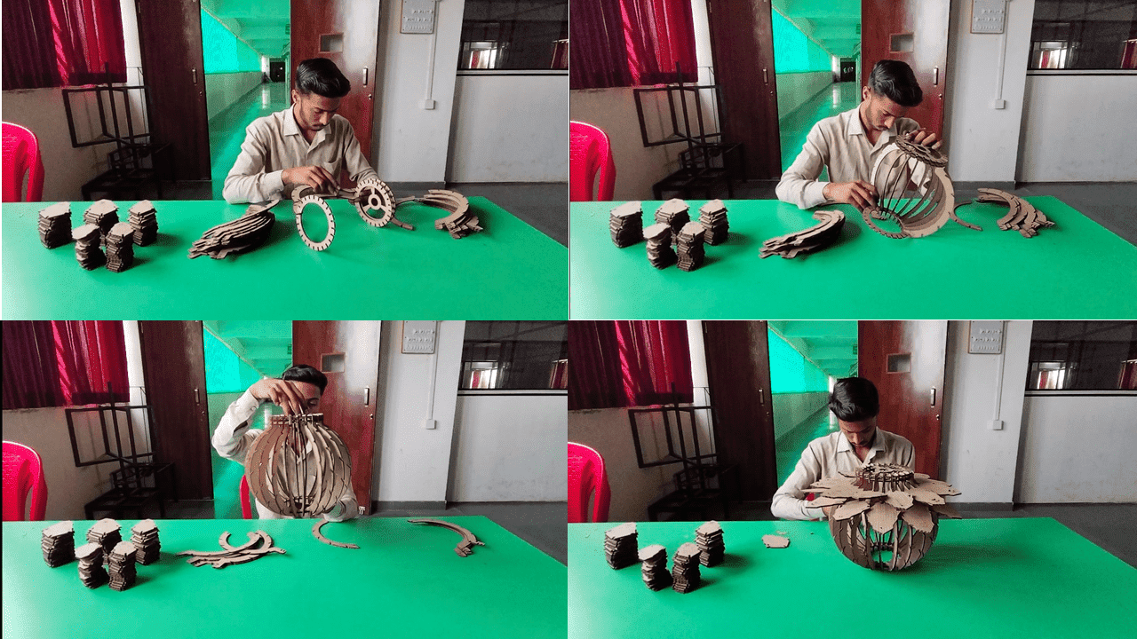
While the assembly process was time-consuming, it was also very enjoyable.
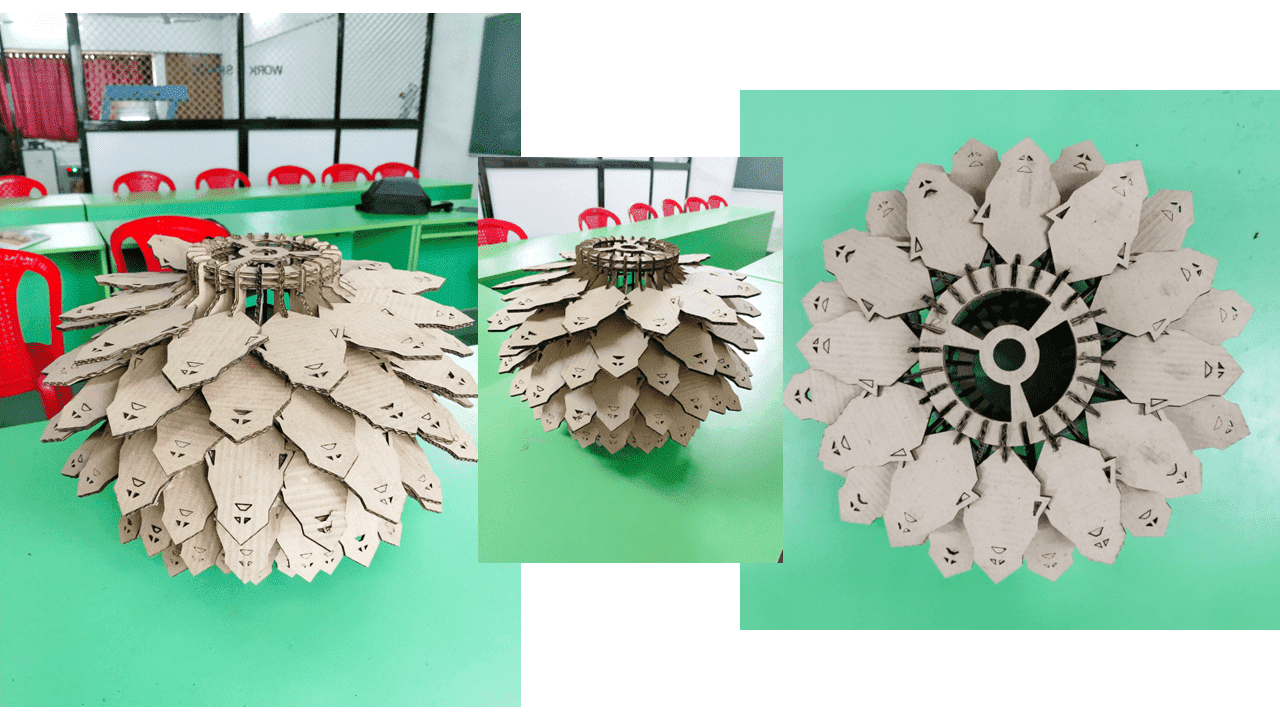
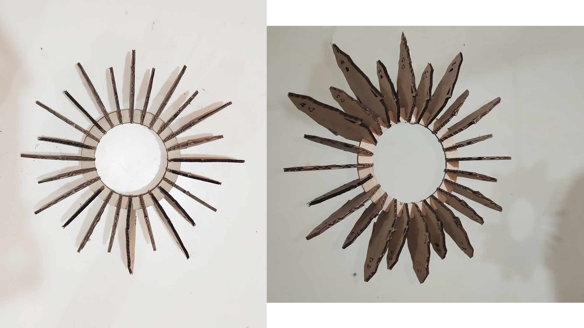
In Below image I have assembled the parts in different manner which are forming a ring.
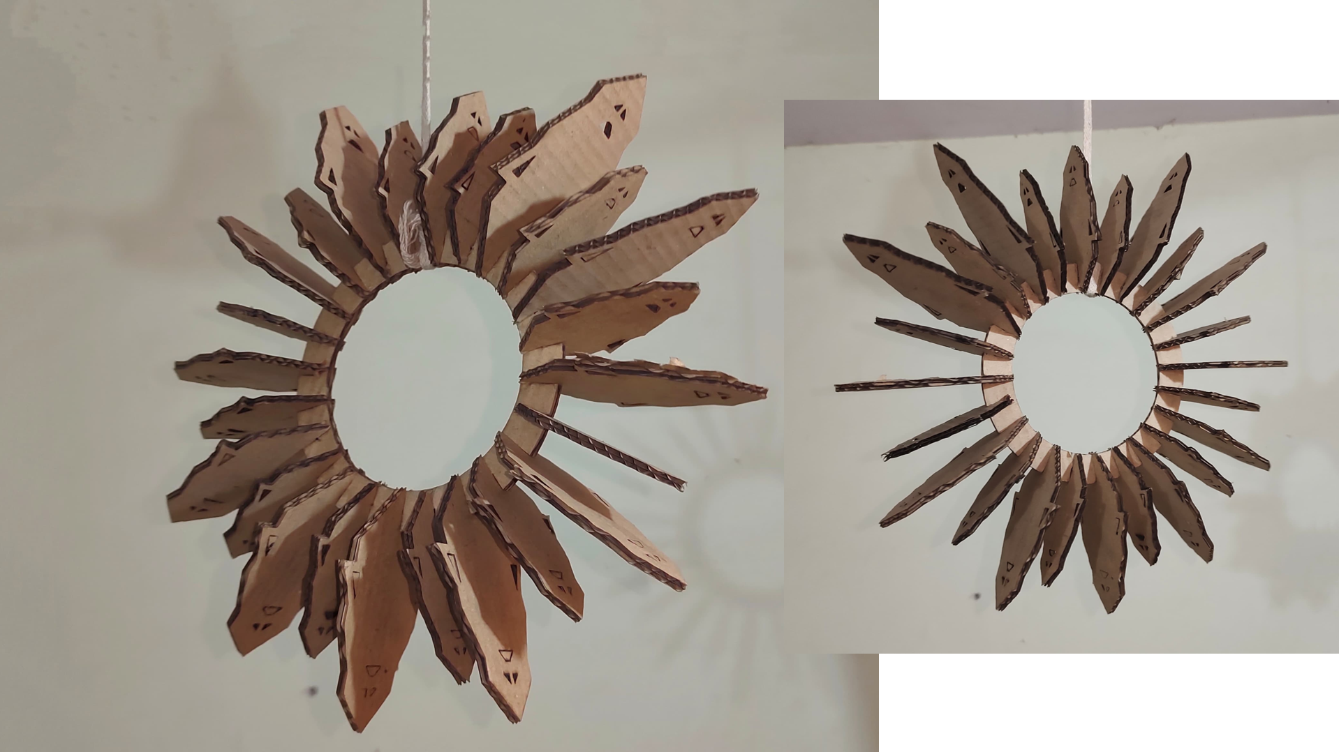
This is the final product, created using laser cutting technology! The cuts are incredibly fine and accurate, demonstrating the capability of creating complex 2D structures with this remarkable technology.
Also, I calculated kerf of material that I have used, The original thickness of cardboard is 4mm and after cutting it becomes 3.87mm. So, I got the kerf of cardboard is 0.13mm.
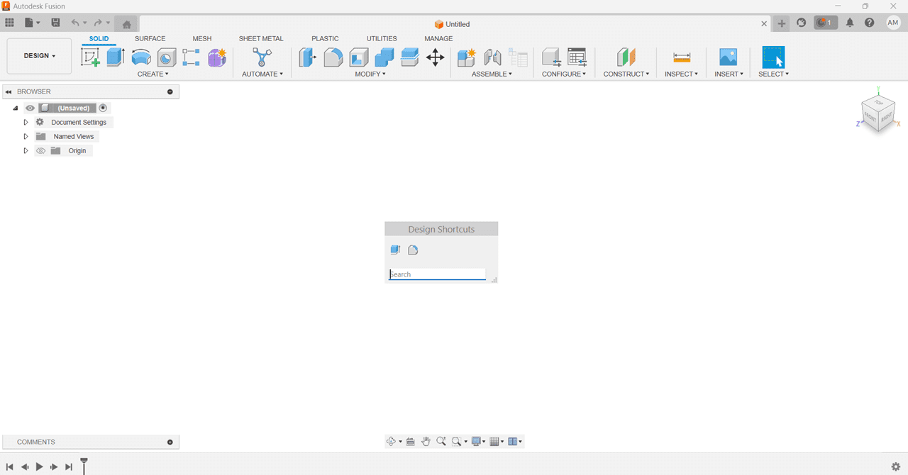
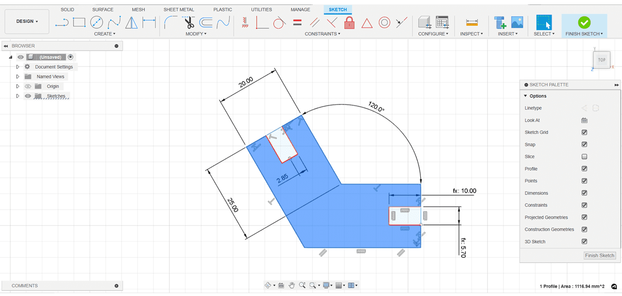
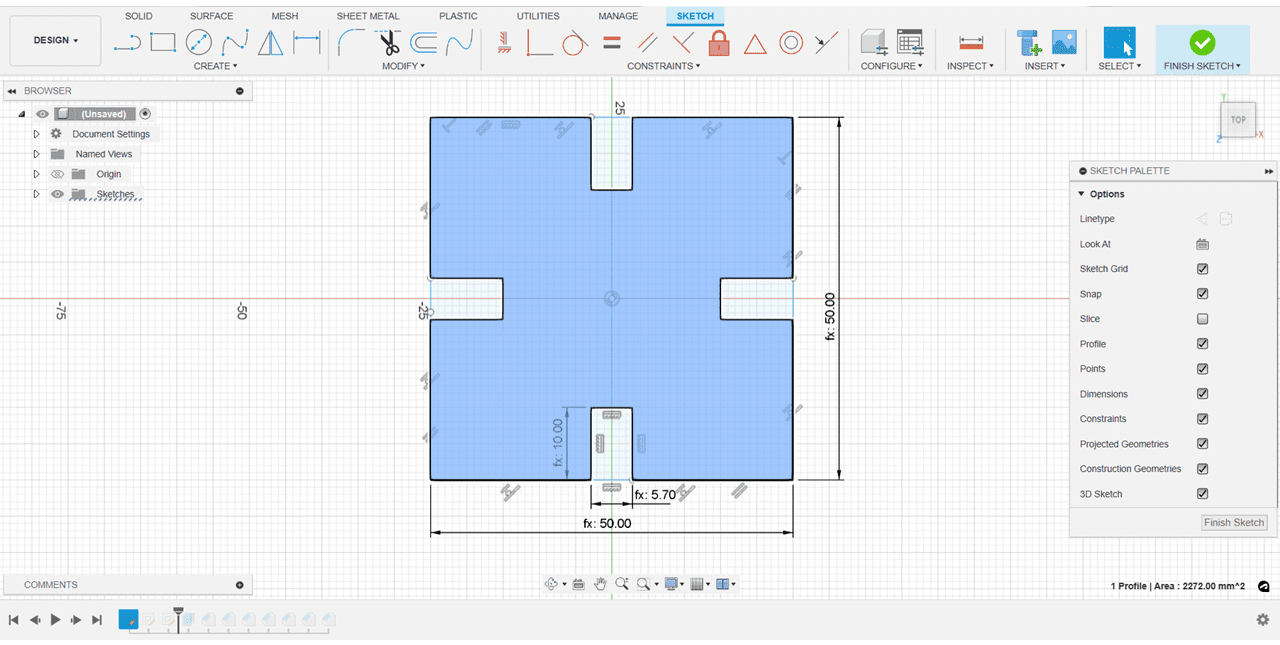
For the parametric design I uesd the fusion 360, in this I tried to design the shapes which can be assembled in multiple ways.
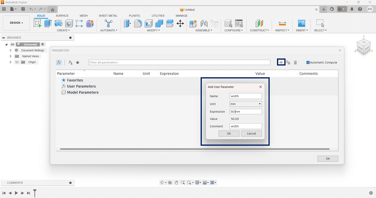
Firstly I opend the Fusion 360 and used the shortcut Key - "S" for search anything, in that I search for the Parametric Design.
After that clicked on the Plus sign for creating new variables, entered the values such as Name, Expression and Comment.
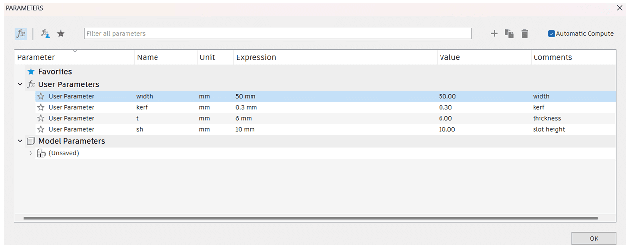
These are the variable that I have created in Parameters window.
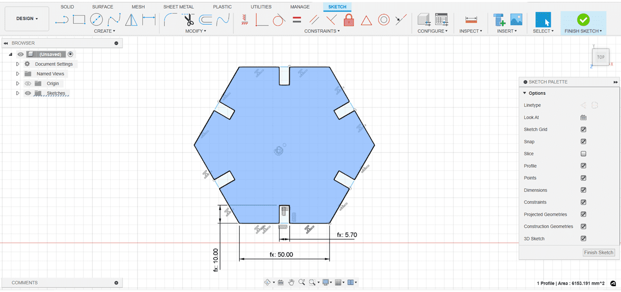
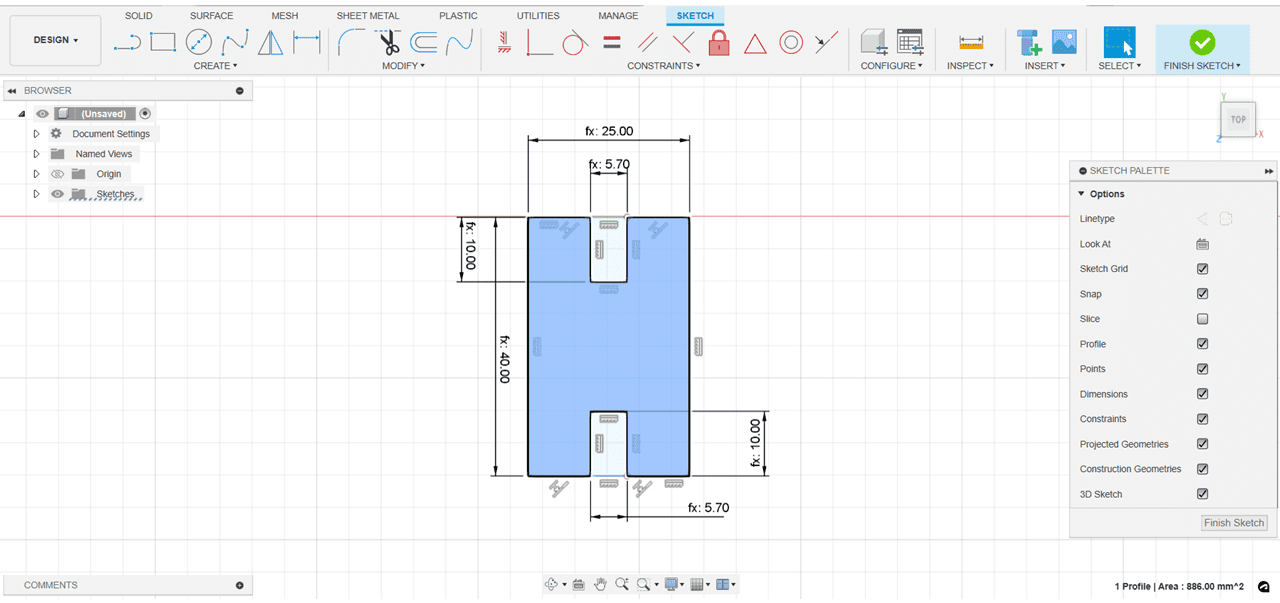
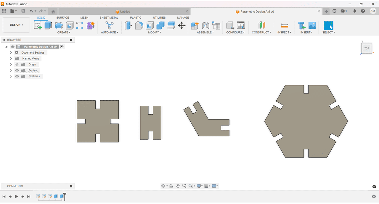
I designed a Hexagon and created the slots on its all sides.
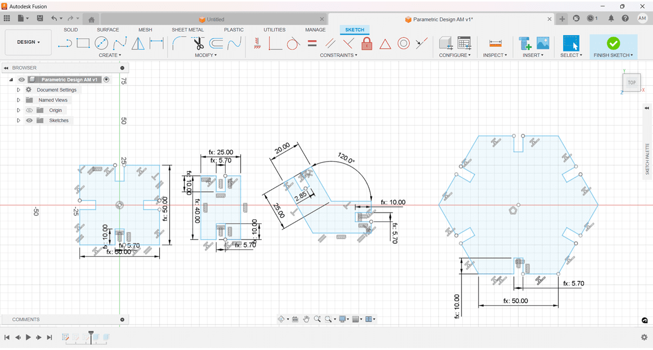
Then I Extruded all the above parts by some Thickness.
I Exported the files in DXF format for laser cutting.
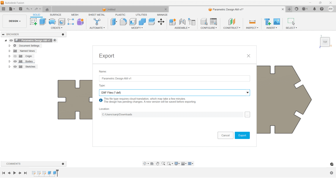
I used the Laser CAD software for laser cutting, Imported the DXF File using Import option or CTRL + I shortcut.
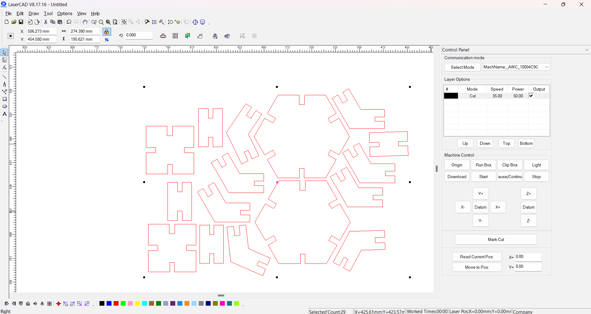
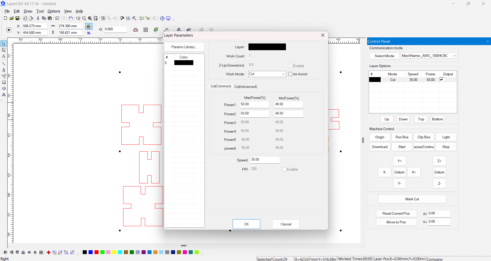
Laser Cutting Parameters:
Power :
Max - 50%
Min - 40%
Speed : 35
I used cardboard of 5mm thickness for the cutting.
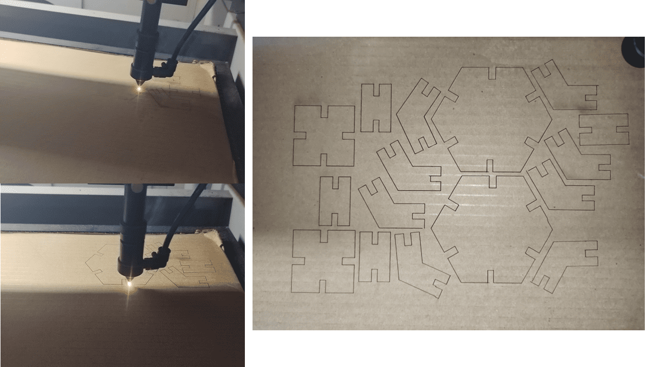
After Completion of cutting i removed all the parts from cardboard.
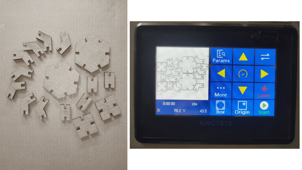
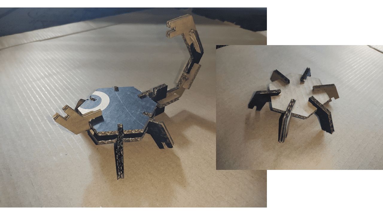
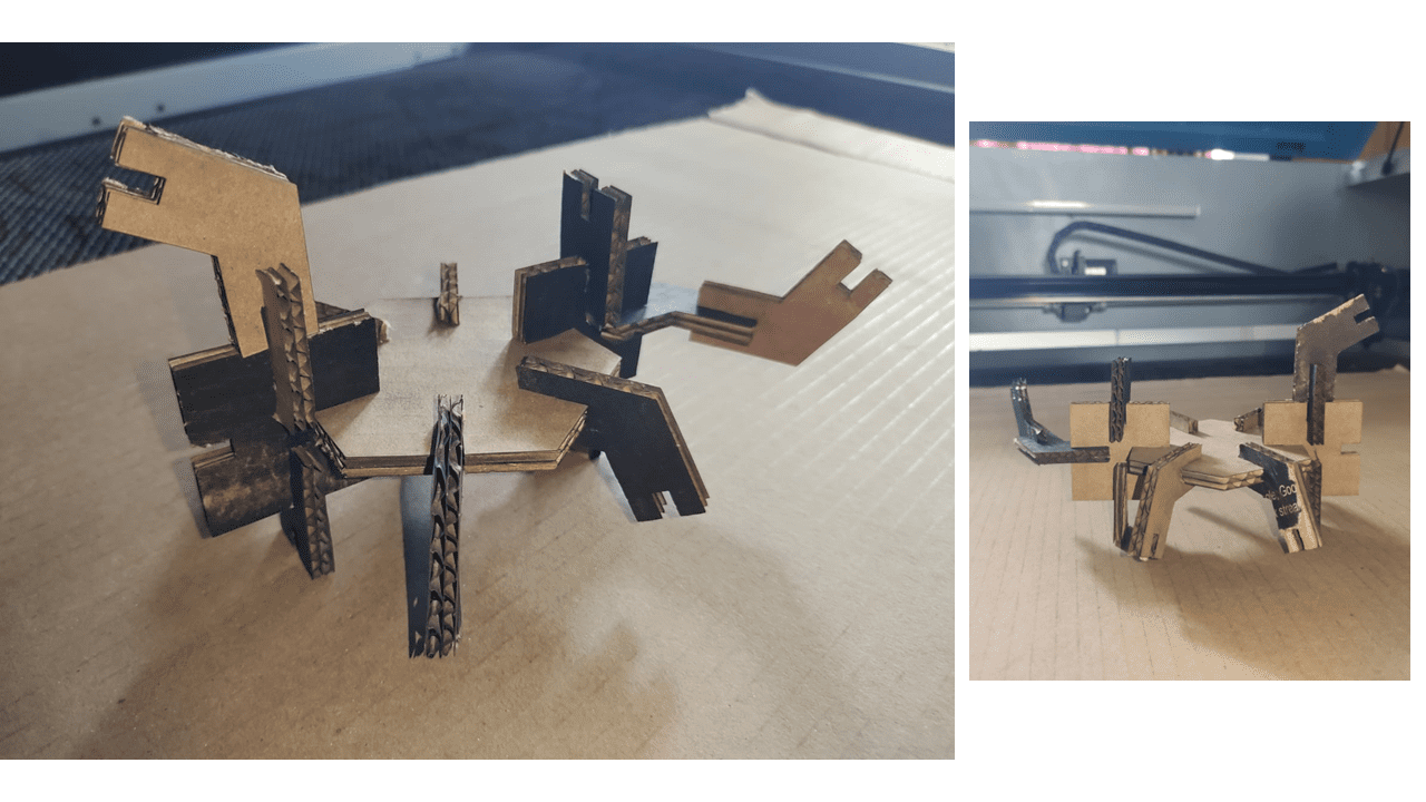
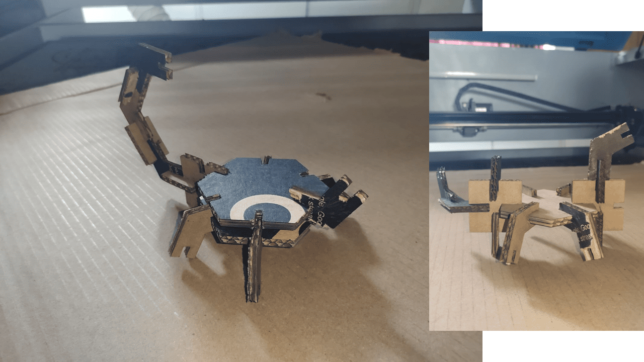
These are the different shapes that I have tried the shapes are looks like Spider, Scorpion, etc.
LaserCad
SOLIDWORKS to Sketchfab Plugin
SolidWorks - Lamp assembly.
DXF File - Lamp.
DXF File - Parametric Design in Fusion 360..