Mechanical Design and Machine Design
The entire thing is documented on Siddarth's page.
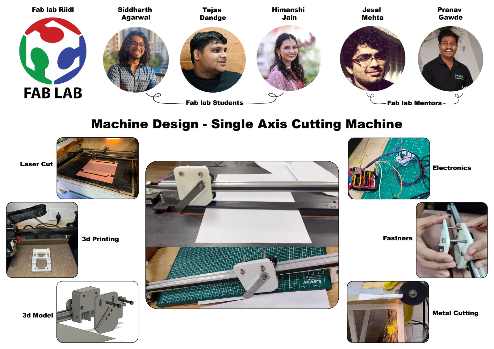
Poster
Final Video
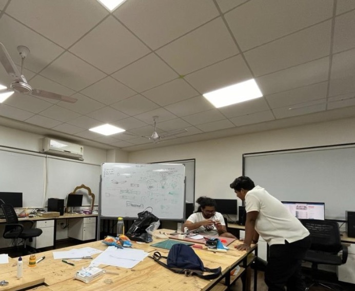
Planning
We started with ideation first where we 3 along with our mentors sat and discussed the idea which we initially had.
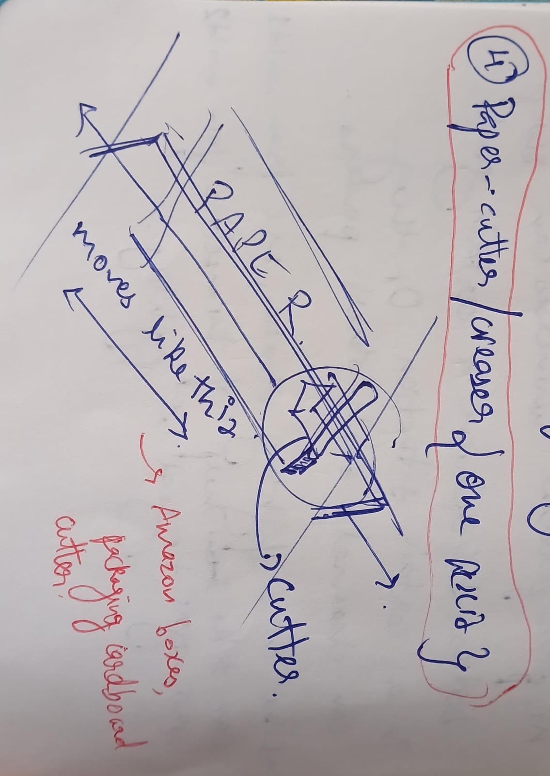
Initial ideas:
1. Clay 3d printer
2. A pen plotter on wheels
3. A conveyor belt robot
After that we finalized 1 idea on which we ideated more and came to a conclusion that we are making a linear actuator which will cut paper.
Why did we select this idea?
Well, as designers, we work a lot with paper for making prototypes. Paper is like our starting point for bringing ideas to life. But sometimes, the old-fashioned way of cutting can be slow and tricky. So, we're building this machine to make our lives easier. It's all about making our design process smoother, quicker, and more precise. With this machine, we can turn our wildest ideas into reality faster than ever before!.
This is how our classroom looks!! It’s papers everywhere.
Inspiration
To create this product, we delved into the documentation of Quentin’s Beehive along with the Tea Dipping machine from last year which our instructors told us about. By studying the making and funcitoning of these existing machines, we understood better the requirements and for our own machine.
List of Materials:
After that we looked at different materials available, what materials we have, what we do not have. And we made a list of thigns we will be needing. This list eventually translated into our checklist when we went shopping. A lot of this was based on Quentin’s Beehive documentation as our primary goal was to replicate the basic Beehive to learn machine-building, and change the carriage to serve our purpose of cutting. Based on recommendation from Jesal sir, our machine also swapped out the Kevlar String and Capstan of the Beehive with Pulleys and a Timing belt.
HARDWARE:
- 5x 40mm M5 socket head
- 15x 10mm M5 socket head
- 8x 8mm M3 button head
- 5x M5 nuts
- 2x M3 nuts
- 4x Derlin V-wheel
- 1mt T-slot Aluminium extrusion 20x20mm
- Pulley 20 teeth
- 1.5 mt, 6mm wide timing belt
- Grub screws for the pulleys
- Mild Steel sheet
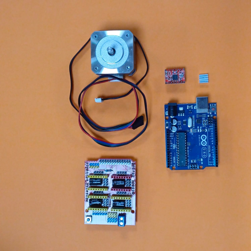
ELECTRONICS:
- 1x Stepper motor Nema 17
- 1x Arduino uno CNC shield with drivers
- 1x Stepper motor driver for Arduino UNO
Procuring Materials
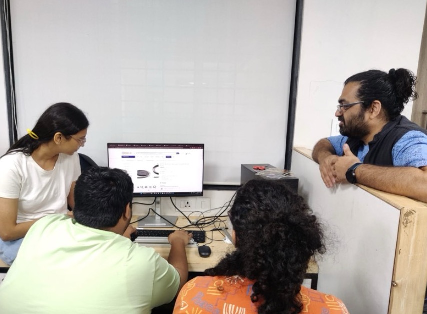
We browsed through Robu.in to explore available components and their prices. This helped us choose the appropriate stepper motors, drivers, and other necessary parts for the project. We did not place any order on Robu as the delivery day was way ahead.
After that, we brought in electronic components from Lamington Road, Mumbai and for hardware, we went to Nagdevi street, Mumbai. There we learned a lot about different materials available, and their usage.
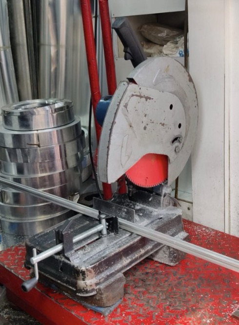
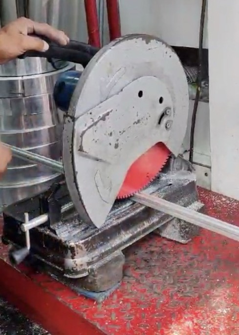
At Nagdevi street, we wanted 50 cm of aluminium extrusions but the entire extrusion was 3.6 meters and it was a new learning for us to see the cutting processof the Al-Ex.
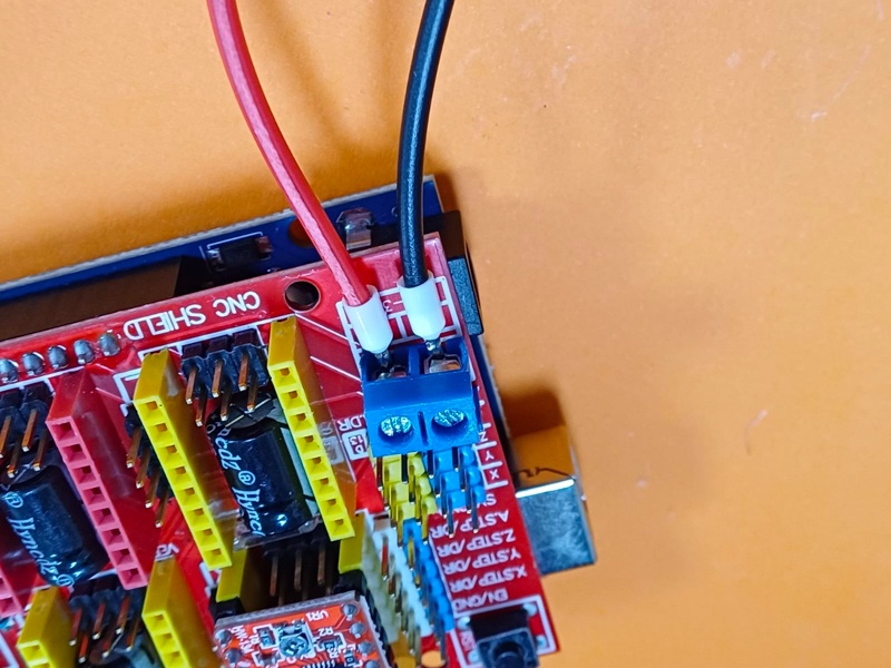
Electronics
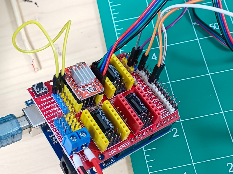
In the time we got all of our hardware, we used our mentor Jesal sir’s stepper motor and driver, along with CNC shield, to learn the connections of all three.
Next, we began learning about the coding of the motor as per our design. While Tejas and Himanshi went to the Nagdevi market, Siddharth stayed back and completed the remaining coding and electronics.
The coding of the electronics was done on the Arduino IDE.
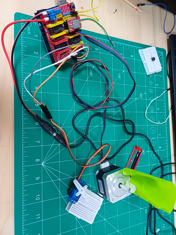
We first made just the motor rotate:
Then we added the servo:
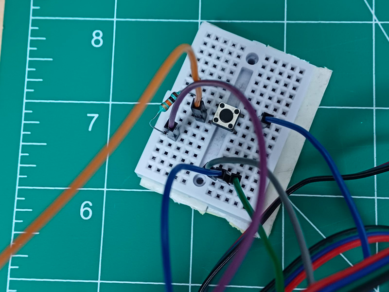
Finally, we added a button on a breadboard to trigger the motors.
We programmed it such that first the servo would go from 0 to 180 degrees to lower the Z-axis and the blade. Next, the stepper would run enabling the blade to slice through the paper. Finally, the servo would go from 180 to 0 degrees lifting the Z-axis and then the stepper would rotate in the opposite direction so that the blade returns to the starting point.
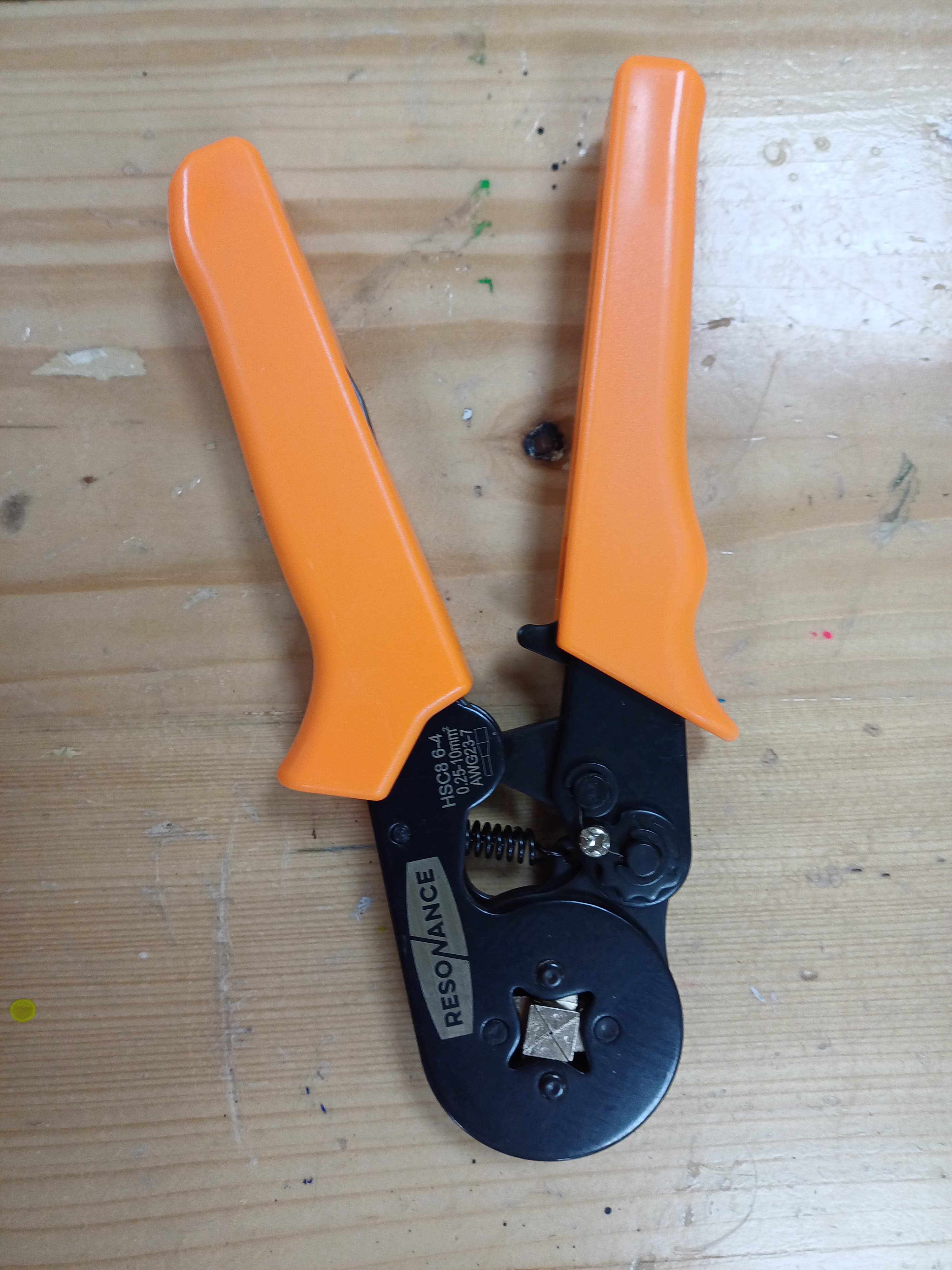
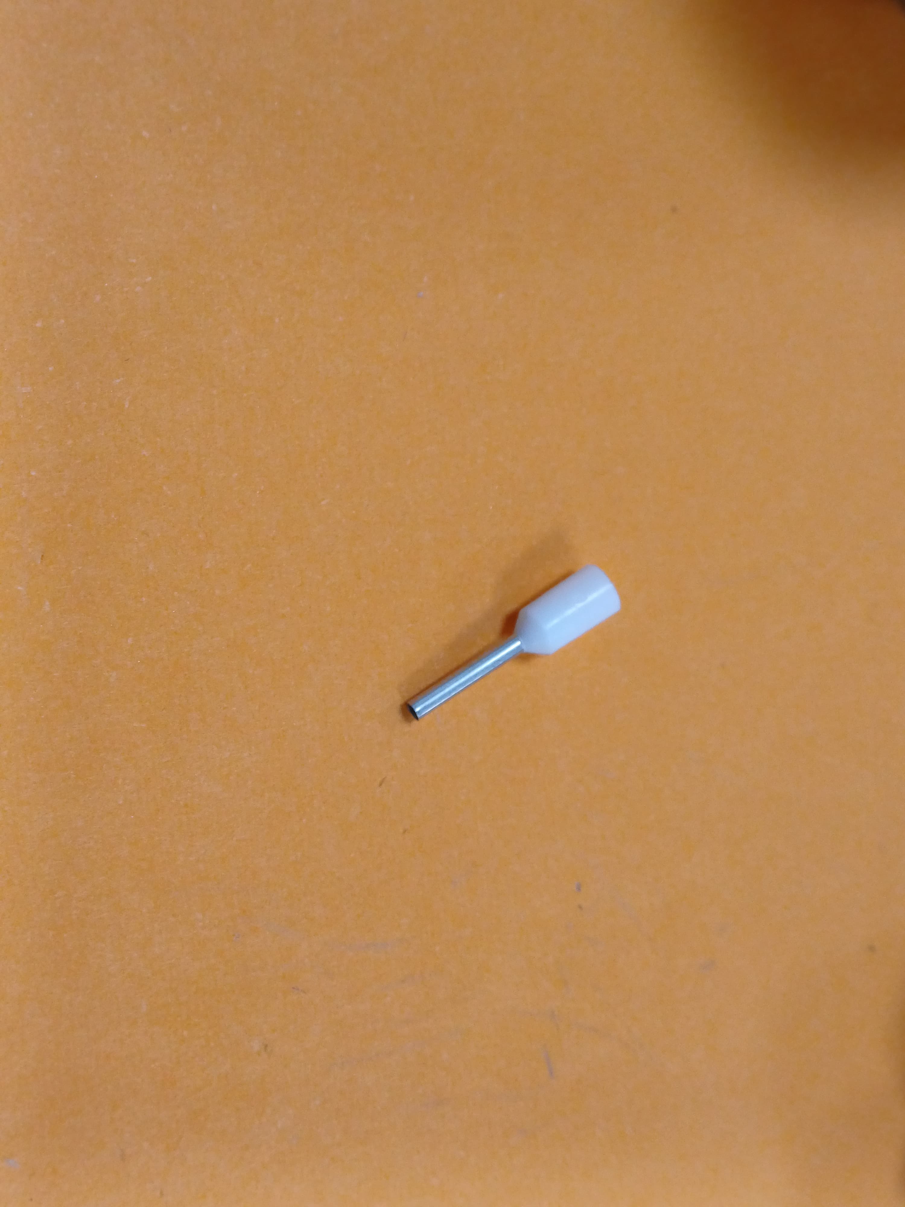
Eventually, we learnt how to crimp the wires using a crimper tool.
3d Modelling
There were three major parts that made the linear axis machine: - Endcap with Motor - Endcap with Pulley - The Carriage
We once again referred to Quentin’s Beehive machines’ 3D files to model our own parts.
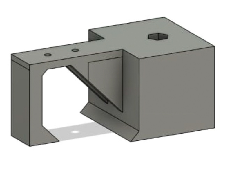
Endcap design was the part which i did, detailed documentation is there on siddharth's page.
For the end caps, we made the design and after taking the guidance of our Mentors, we understood that our endcaps will not take the weight of aluminium extrusion as it was not stable in the design, also we made a 5mm rod on one side of the end cap for the pulley to rotate but our mentors suggested that it will break.
We had to scrape these endcaps.
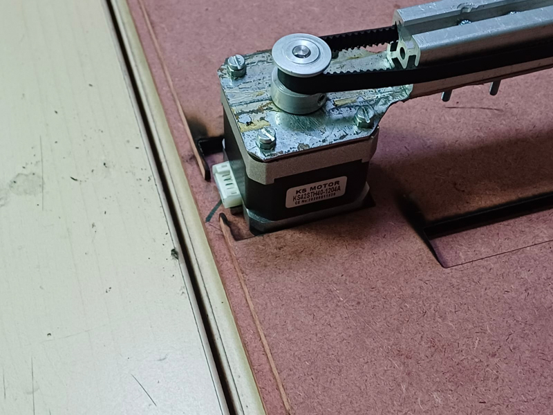
Instead, we decided to use a metal sheet at the motor end of the machine. This was suggested to us by our instructor Pranav Sir. We would attach a metal sheet to the stepper motor while the motor faced up. This way the motor itself would act as a base. Metal working was again totally new for us, so it was scary and exciting to learn. (Metalworking will be covered in a later section)
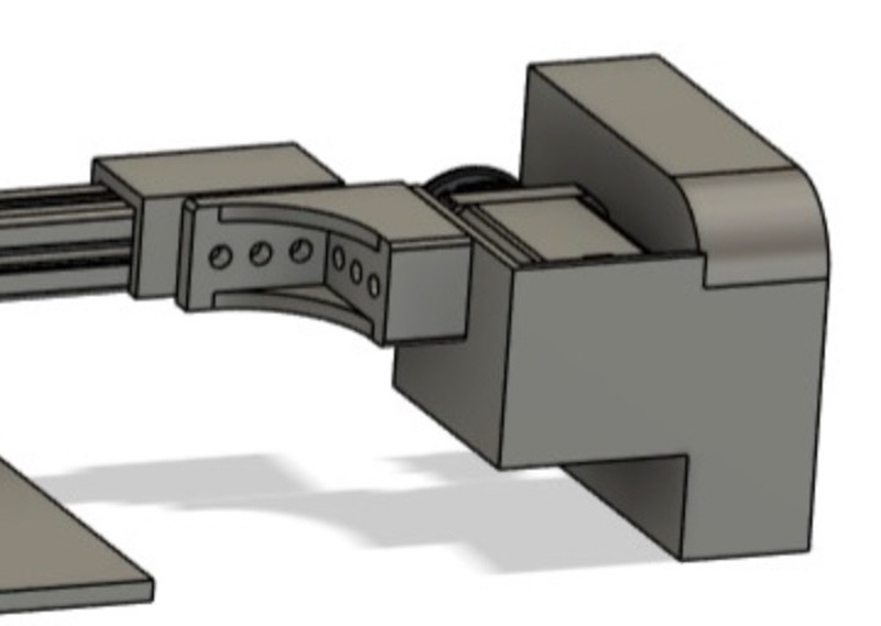
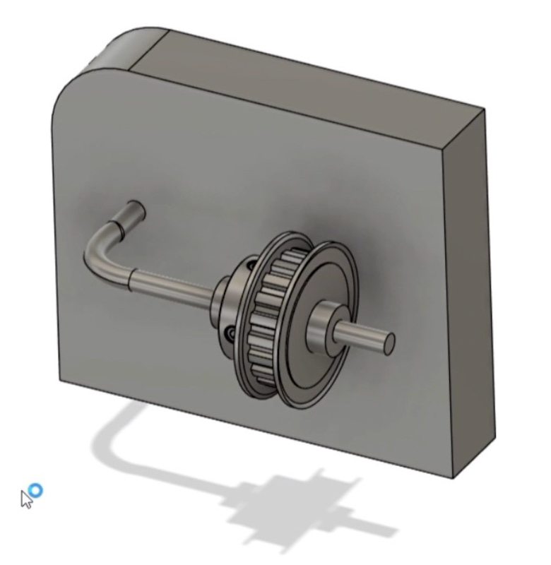
We redesigned the pulley end cap and finally had our 3D models ready for printing:
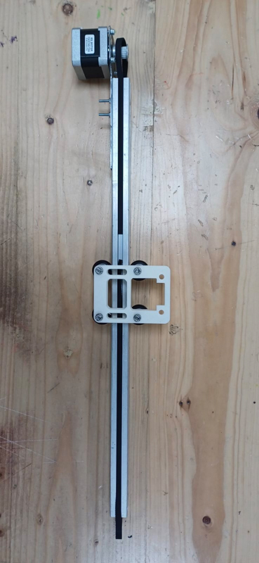
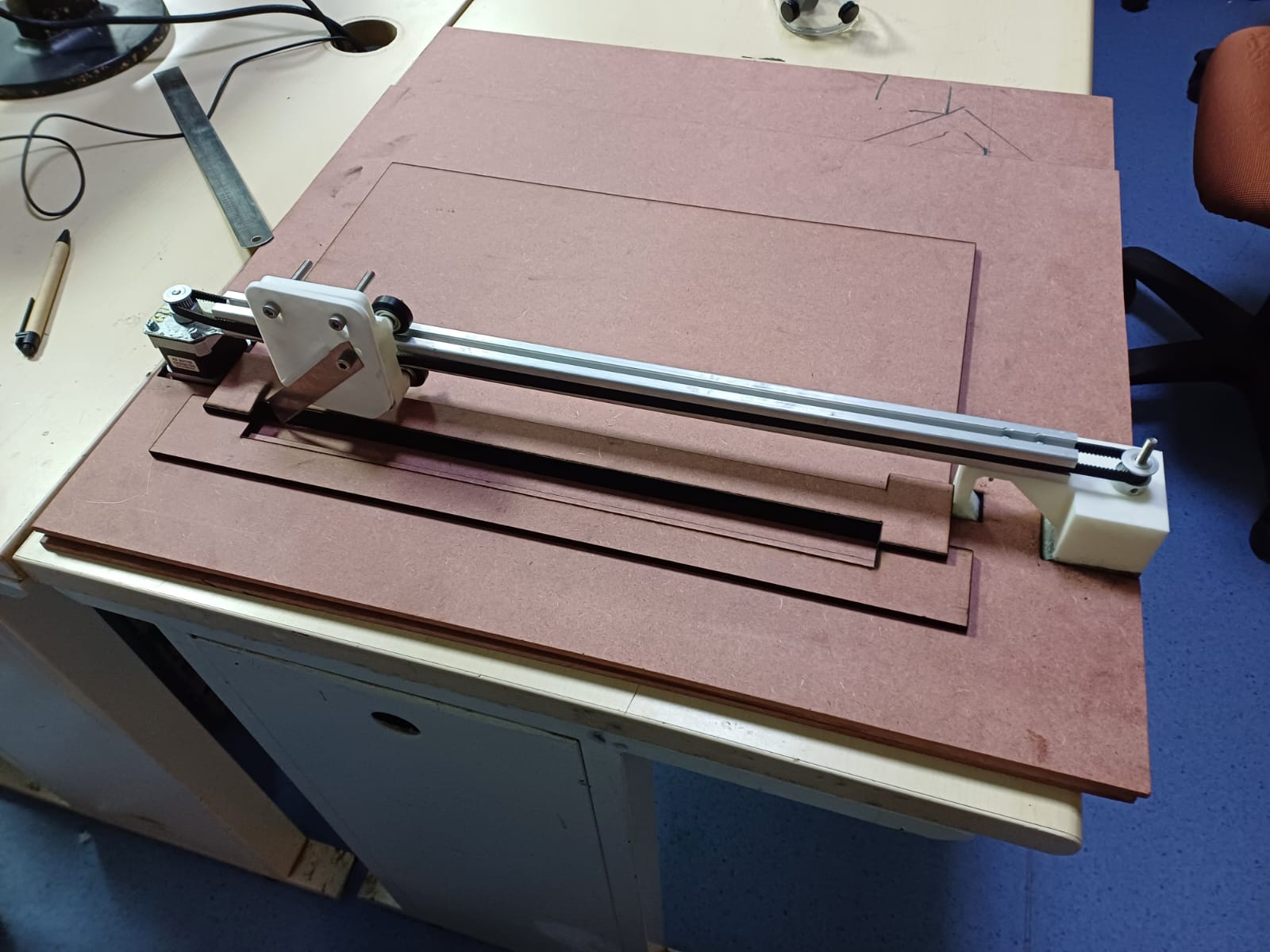
Assembly
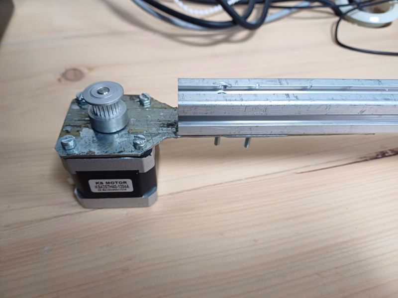
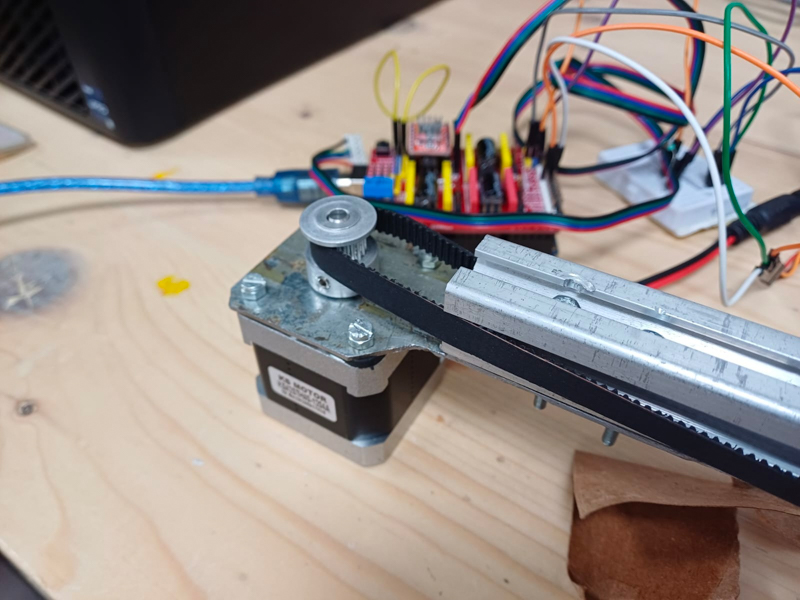
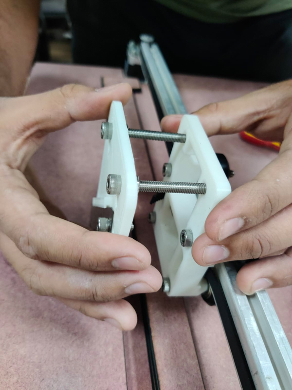
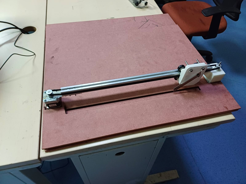
After this, we attached the metal piece with aluminium extrusion with the help of fasteners (nuts and bolts), and then we attached a pulley to the shaft of the stepper motor and connected it to the timing belt. To make sure the pulley and the shaft of the stepper motor were tightly locked, we used a grub screw. This made sure that the rotation of the motor would make the pulley rotate along with it without slippage.
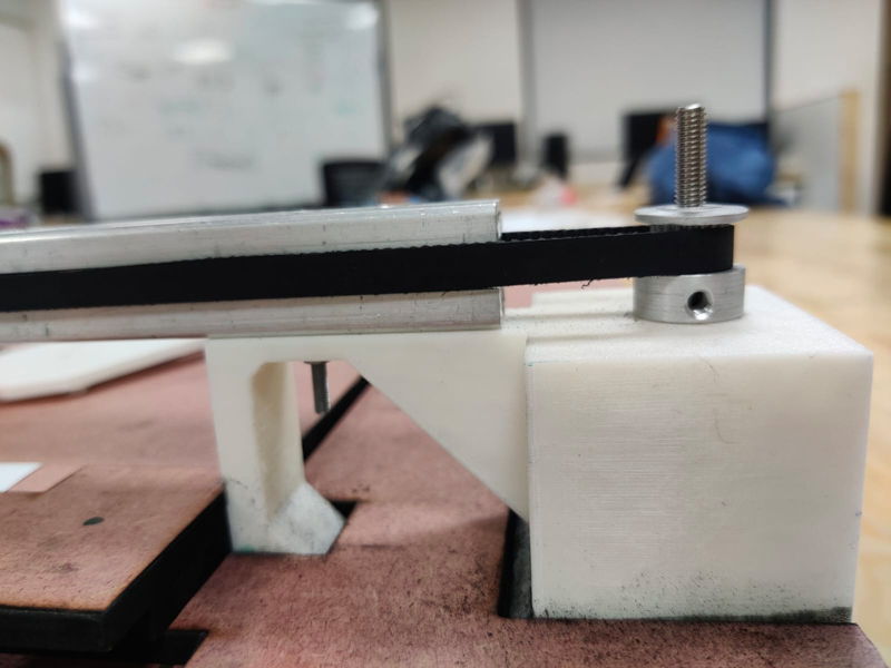
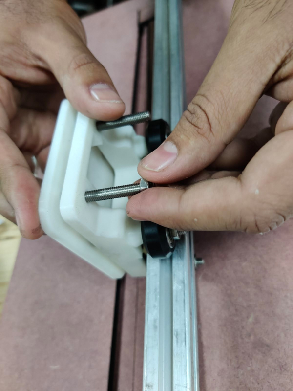
Next, we attached the other end cap with the free to rotate pulley:
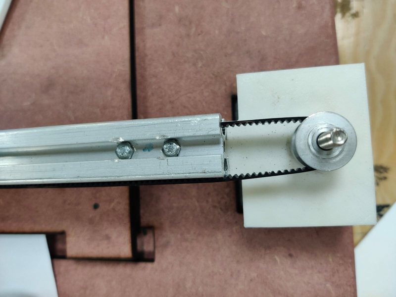
We used an M5 bolt and nut to make the shift/axis for the pulley to rotate around.
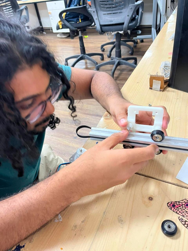
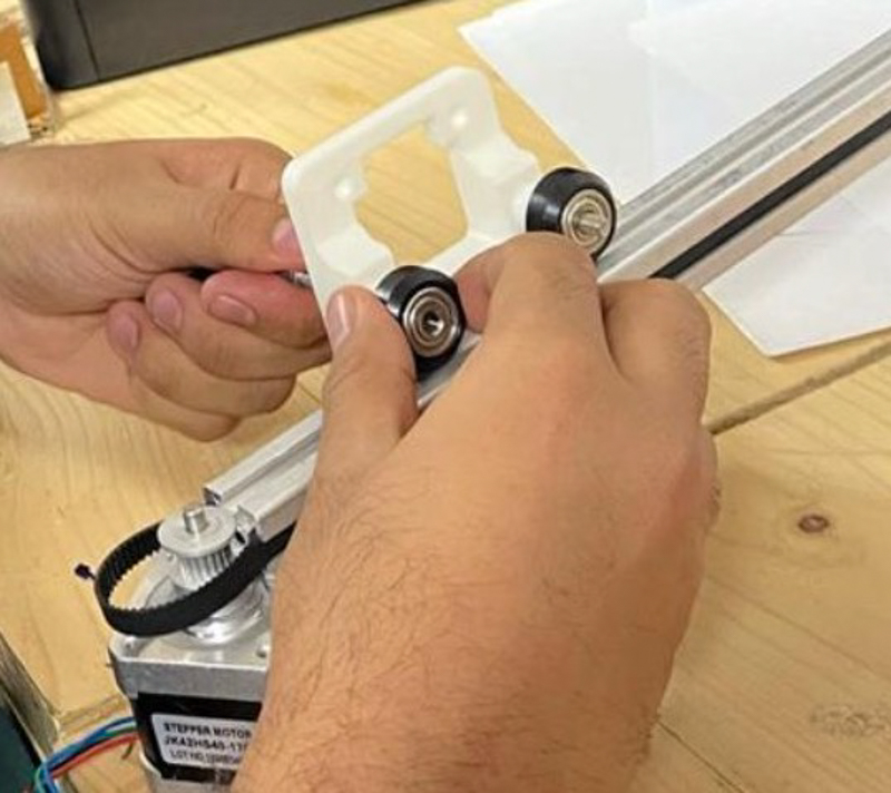
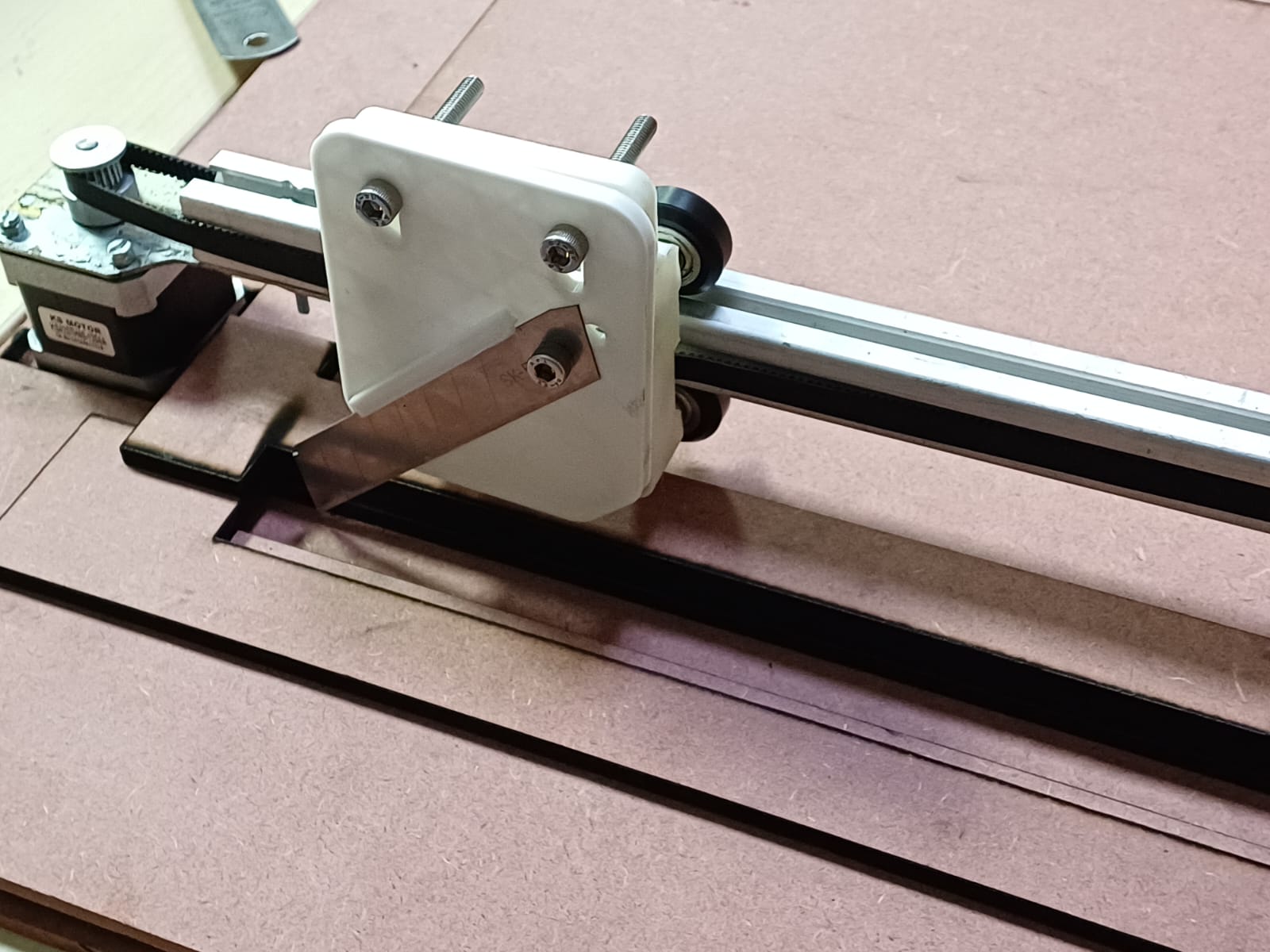
Attaching the delrin wheels
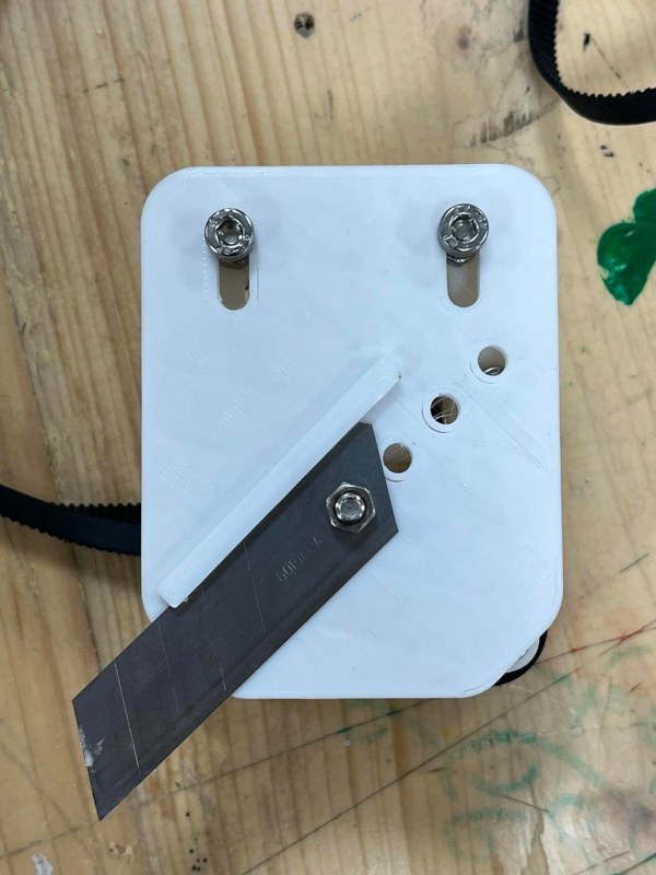
For attaching the shield:
First attach the blade on the slot given in the shield and attach the entire shield with the carriage with the help of m5 nuts and bolts.
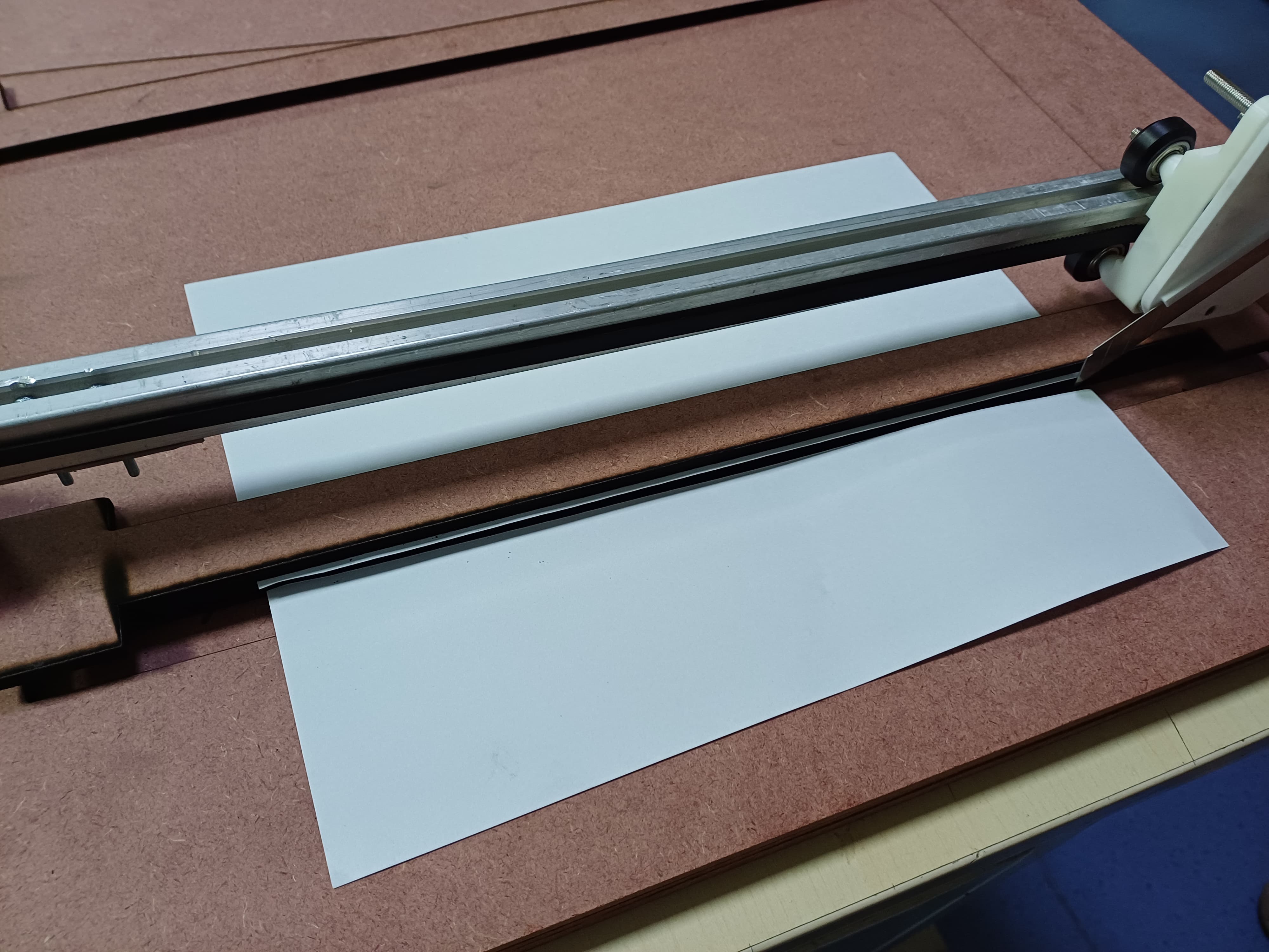
After assembling everything, we began testing the cutting process manually, without connecting the electronics. We moved the carriage by hand during these trials.
We took care to not keep our hand in the way of the blade. Since we were moving it manually, we could coordinate and take care of not cutting into each others fingers!
Problems we were facing:
We required something to hold and align the paper.
We had 2-3 different sizes of blades, so we chose one sharp blade and adjusted its height accordingly. We provided multiple holes to fix the blade at different heights, depending on our requirements.
We needed some downward force for the cutter to make clean cuts without pulling the paper along with it.
We got back to the drawing board to ideate on how the to-be-cut paper could be held in place.
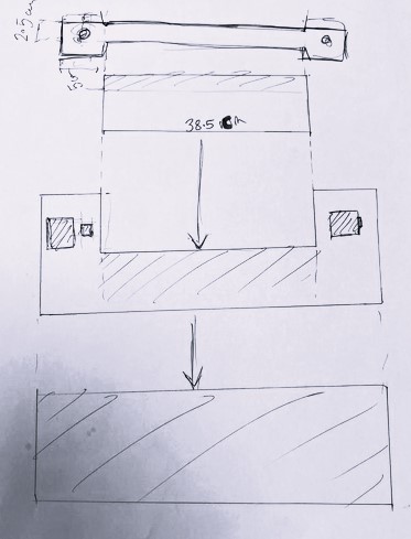
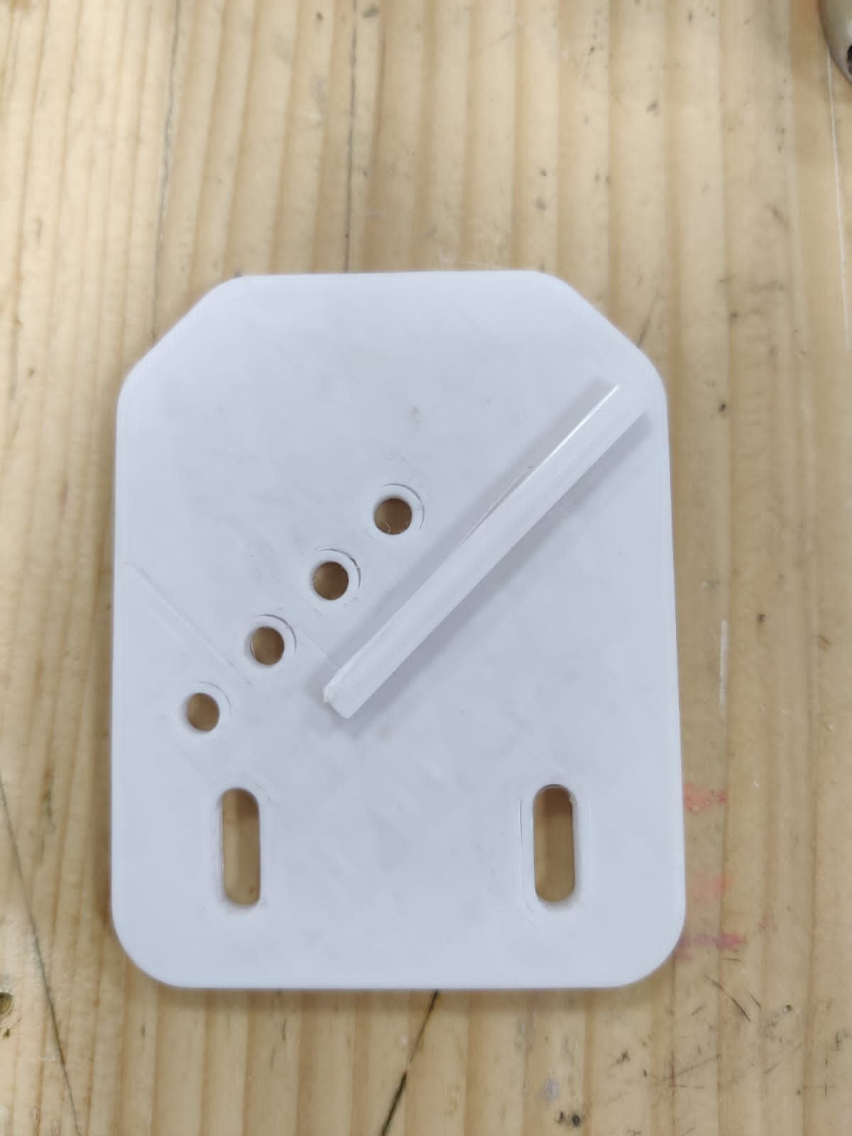
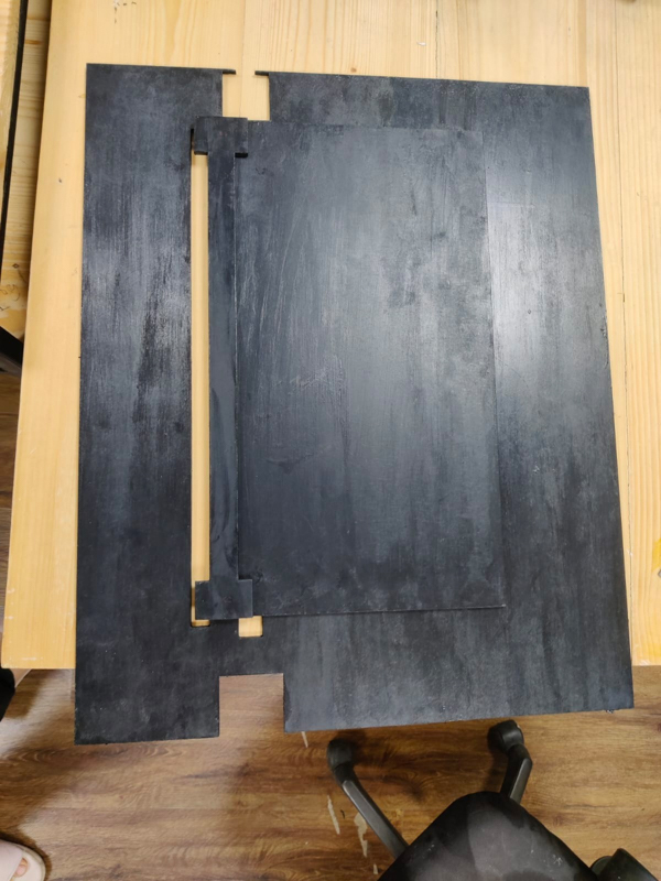
We were initially trying to cut the paper from the tip of the blade but that was not helping as it would just drag the paper along due to no downward force. So, we made a base which had a GROOVE and then we lowered the blade height so now the tip is not cuttin but the center part of the blade is. We also added weight on the paper which held the paper in place.
This base with groove was laser cut:
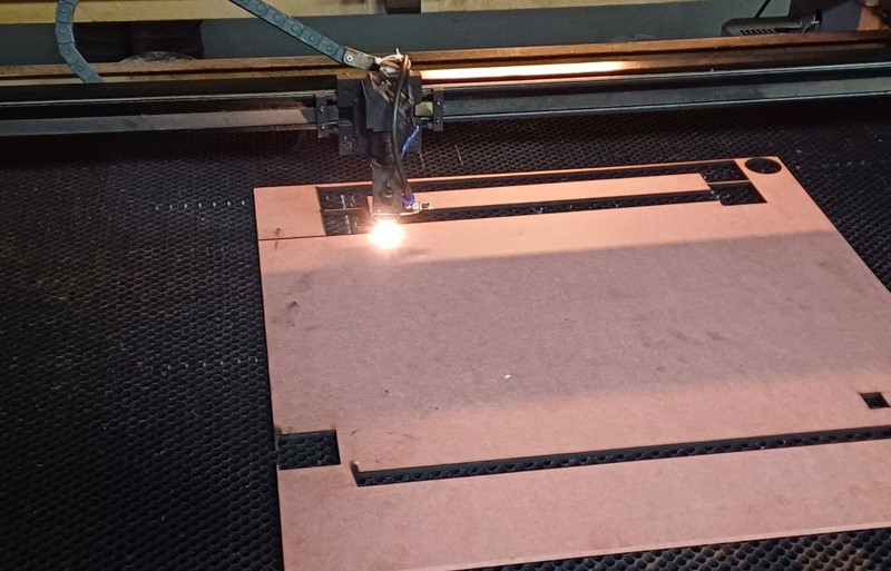
Here you can see the groove
We even gave the endcaps a depression so that the machine did not move around relative to the base.
After this we painted the base.
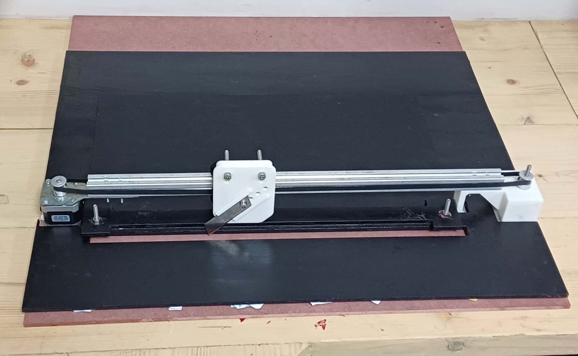
Final
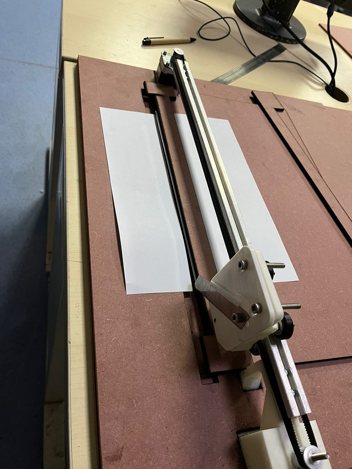
In the baove video we manually held the mdf strip to add weight. The plan was to use screws and tighten the mdf strip on the paper. This way the paper would not move.
Individual Contribution and Learnings
During this project, I played a significant role in procuring the necessary materials. I visited local markets and suppliers, which allowed me to gain a detailed understanding of different materials and their specific applications in machine building. This hands-on experience helped me learn about the variety of materials available and how to select the appropriate ones for our project. It was an invaluable opportunity to see firsthand the practical aspects of material procurement and handling, which greatly enriched my knowledge in this area.
In the realm of 3D modeling, I was responsible for creating one of the parts for our machine. Collaborating with my team, we divided the modeling tasks to ensure efficiency and accuracy. This task honed my skills in 3D modeling software and taught me how to design parts that are not only functional but also manufacturable. Additionally, I participated in the 3D printing process, where I helped set up and monitor the printers, ensuring that the printed parts were of high quality and fit for assembly.
The assembly phase of the project was a collaborative effort where I worked closely with my teammates. Together, we tackled the assembly of the machine parts, troubleshooting issues that arose and ensuring that the machine was put together correctly. This experience significantly improved my teamwork and collaboration skills, highlighting the importance of effective communication and task division in a team setting.
Another key area where I contributed was in creating laser cutting files for the base of the cutter. I ensured that the designs were precise and optimized for a clean and efficient cut. This task provided me with a deeper understanding of the laser cutting process, from file preparation to the actual cutting, ensuring precision and accuracy in the final product.
Throughout the project, I developed strong problem-solving skills. The iterative process of design, testing, and modification taught me the importance of resilience and adaptability. I learned how to troubleshoot and find solutions to unexpected challenges, which is crucial in any engineering or design project. Overall, this project was a comprehensive learning experience that enhanced my technical skills in material selection, 3D modeling, printing, and laser cutting, while also improving my ability to work effectively within a team.