Output Devices
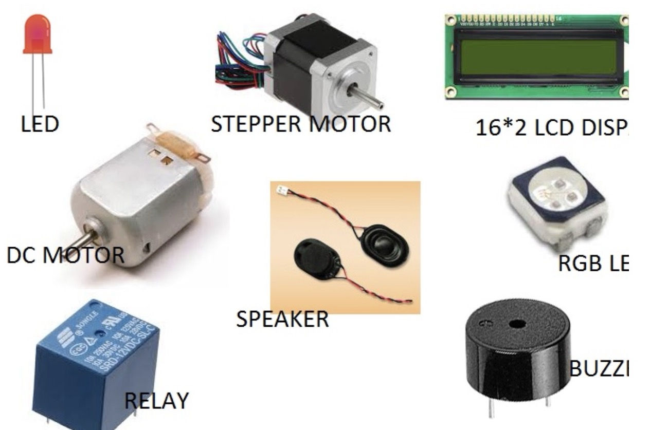
Output devices are components that convert electrical signals into various forms of output, such as visual displays, sound, or physical movement. Examples include LEDs (Light Emitting Diodes), speakers, motors, and displays like LCDs (Liquid Crystal Displays) or OLEDs (Organic Light Emitting Diodes).
In this week';s assignment is is to add an output device to a microcontroller board and program it to do something and the group assignment is to measure the power consumption of an output device.
I started with understanding output devices first. Output devices can be broadly categorized into several types, including visual output devices, audio output devices, physical output devices, Display Devices, Motion Devices and Projection Devices. Let's explore each category a bit in detail first.
Visual Output Devices:
a. LED Matrix Displays
b. E-paper Displays
c. Laser Light Shows
Audio Devices:
a. Speakers
b. Headphones
c. Buzzers
Physical Output Devices:
a. Actuators (such as solenoids and pneumatic cylinders)
b. Mechanical switches or relays (for physical interaction)
Display Devices:
a. LED (Light Emitting Diode) Displays
b. LCD (Liquid Crystal Display) Screens
c. OLED (Organic Light Emitting Diode) Screens
d. CRT (Cathode Ray Tube) Monitors (less common now)
Motion Devices:
a. Motors
b. Servo Motors
c. Stepper Motors
Projection Devices:
a. Projectors (DLP, LCD, LCoS)
b. Holographic Displays
Working with Servo motor as an output device
I had made a smart cut for that there was ultrasonic sensor as an imput and servomotor vas an output so I continued with that project and used servo motor as my output.
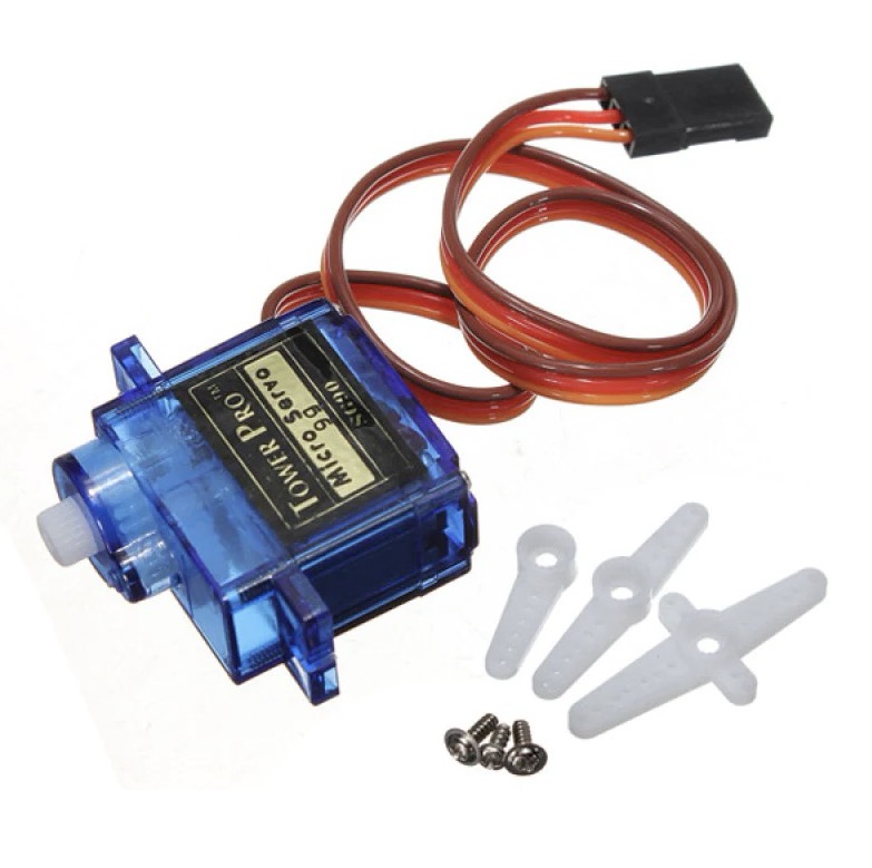
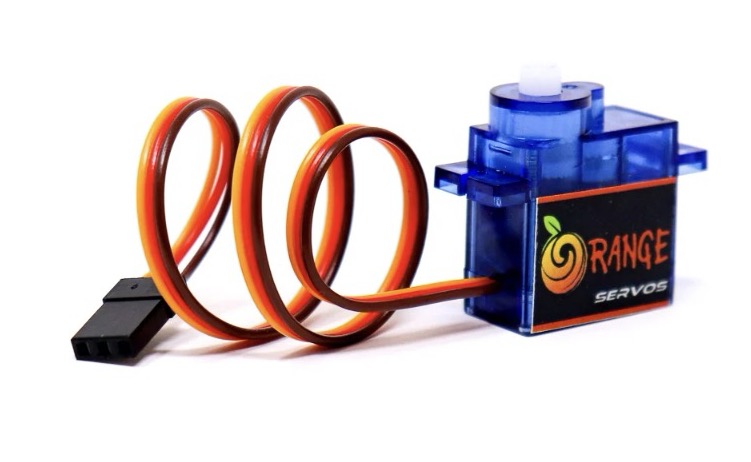
What is a Servo Motor?
A servo motor is a type of rotary actuator that allows for precise control of angular position. It consists of a motor, a control circuit, and a feedback mechanism. Servo motors are commonly used in applications requiring controlled motion, such as robotics, RC vehicles, and automation systems. They can rotate to a specific angle based on the input signal they receive, making them ideal for tasks requiring accurate positioning.
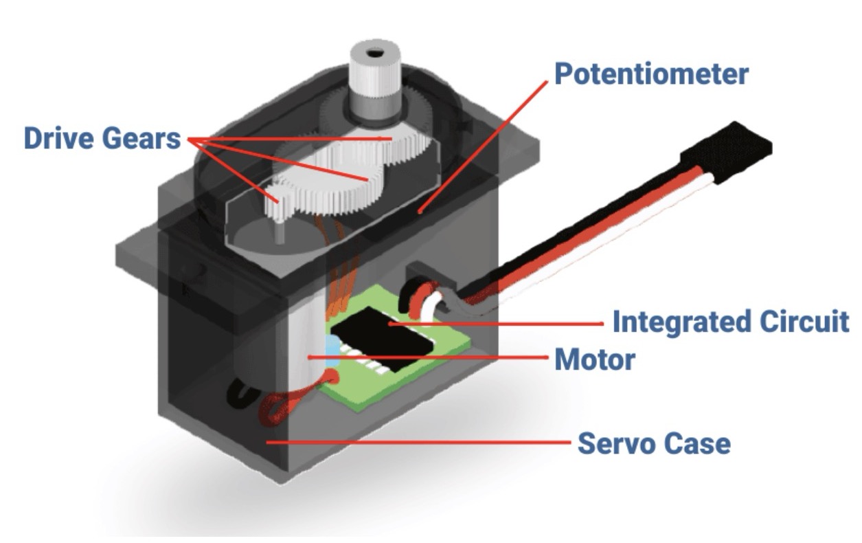
What are the mechanisms of servo motor?
Motor:
The motor inside a servo motor is usually a DC motor, which generates rotational motion.
Gears:
Servo motors often contain a gear mechanism to reduce the rotational speed of the motor while increasing torque. This gearing system allows for precise control of the motor's output shaft.
Feedback Mechanism:
Most servo motors include a feedback mechanism, such as a potentiometer or an encoder, which provides information about the current position of the motor shaft. This feedback allows the motor controller to accurately adjust the motor's position to match the desired position.
Control Circuit:
A control circuit processes input signals, typically in the form of pulse-width modulation (PWM) signals, to determine the desired position of the servo motor. It then adjusts the motor's speed and direction to move the output shaft to the desired position.
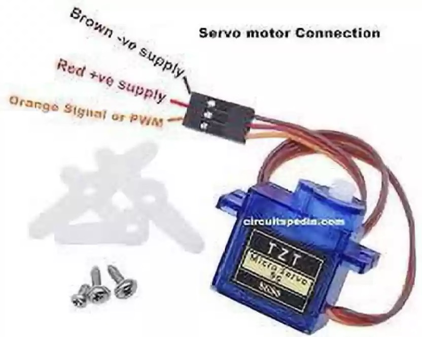
Connections in Servo Motor
1. Power (VCC):
This wire provides the servo motor with the necessary power. It is usually connected to a power source with a voltage appropriate for the servo motor (commonly 5V for hobby servos).
2. Ground (GND):
This wire connects the servo motor to the ground of the power source, completing the electrical circuit.
3. Signal (Control):
This wire carries the control signal to the servo motor. The control signal, often in the form of pulse-width modulation (PWM), determines the position or angle of the servo motor shaft.
Types of Servo Motors
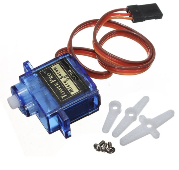
1. Analog Servo Motors:
Basic servo motors controlled by pulse-width modulation (PWM) signals, commonly used in hobbyist projects.
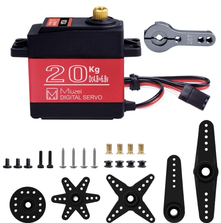
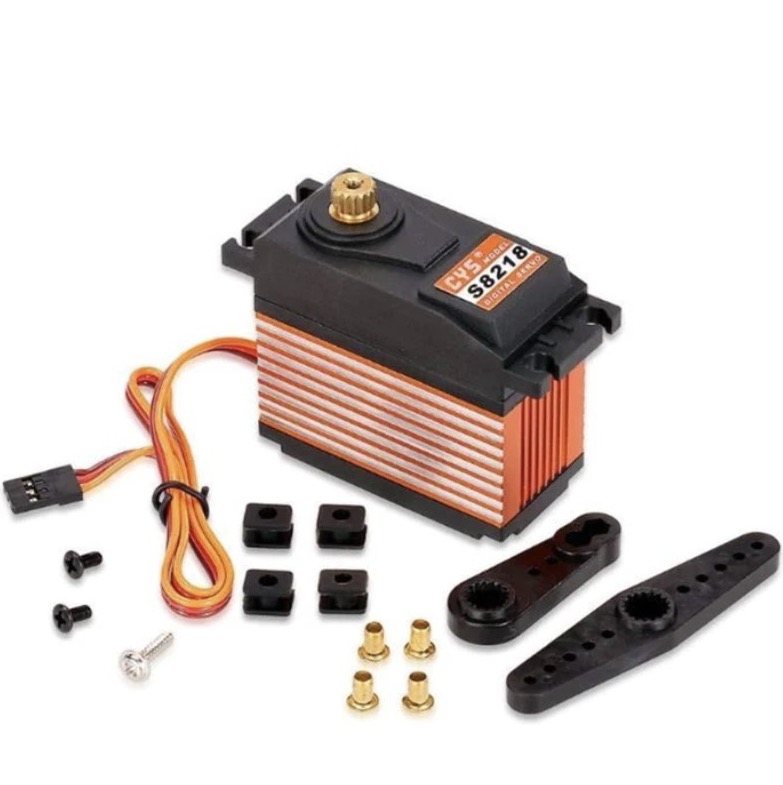
2. Digital Servo Motors:
Advanced servo motors with digital control, offering higher precision and performance.
3. Continuous Rotation Servo Motors:
Servo motors capable of rotating continuously in both directions, often used for continuous motion control.
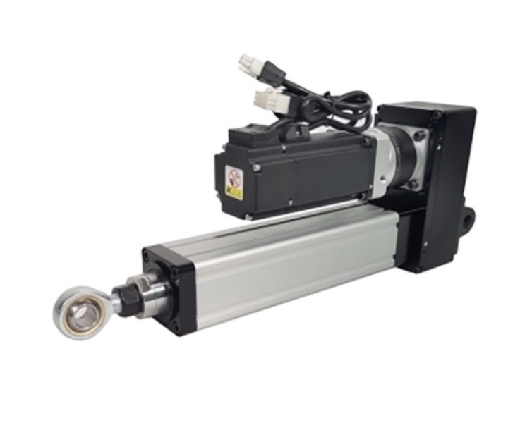
4. Linear Servo Motors:
Convert rotary motion into linear motion, suitable for applications requiring linear actuation.
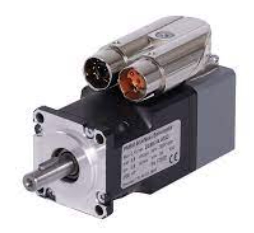
5. Brushless Servo Motors:
Utilize brushless DC motor technology, providing higher efficiency and reliability compared to brushed motors.
6. High-Torque Servo Motors:
Designed to deliver greater torque output, ideal for applications with heavy loads or high force requirements.
The documentation of designing the development board and milling it is done in Week 8.
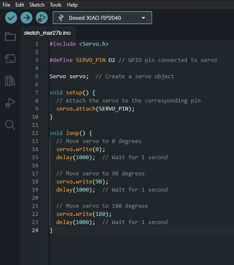
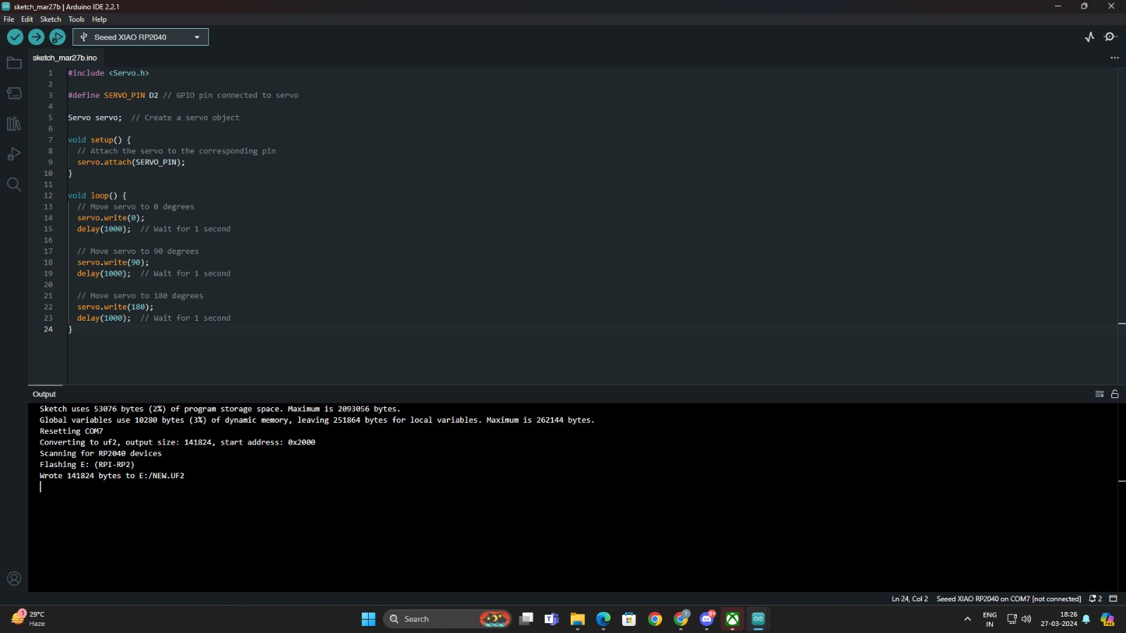
Code sample
    #include

      // Define the servo object
      Servo myServo;

      // Define the pin for the servo signal
      const int servoPin = 2;  // Change to the PWM-capable pin you are using

      void setup() {
        // Attach the servo to the defined pin
        myServo.attach(servoPin);
      }

      void loop() {
        // Rotate the servo to 0 degrees
        myServo.write(0);
        delay(1000);  // Wait for 1 second

        // Rotate the servo to 90 degrees
        myServo.write(90);
        delay(1000);  // Wait for 1 second

        // Rotate the servo to 180 degrees
        myServo.write(180);
        delay(1000);  // Wait for 1 second
      }
Breadboard Testing
For testing the code I did it first on breadboard.
To see the video of the braedboard testing, click below:
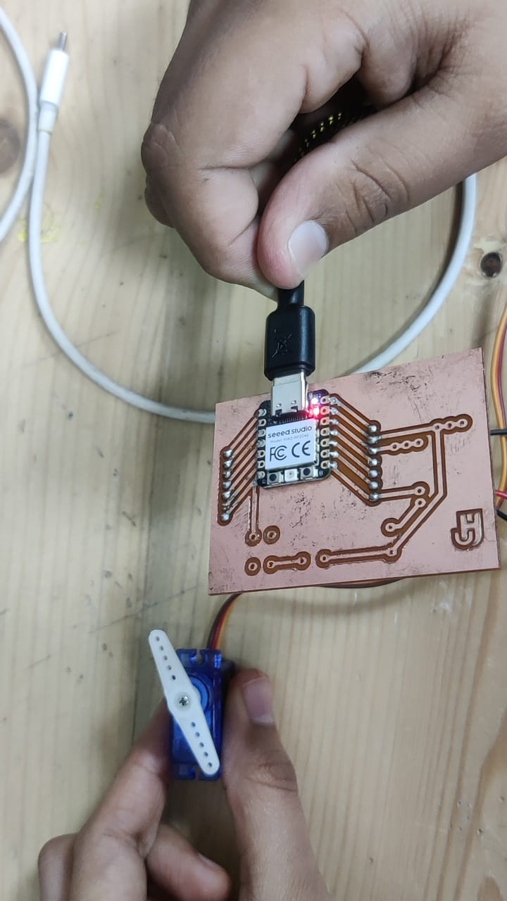
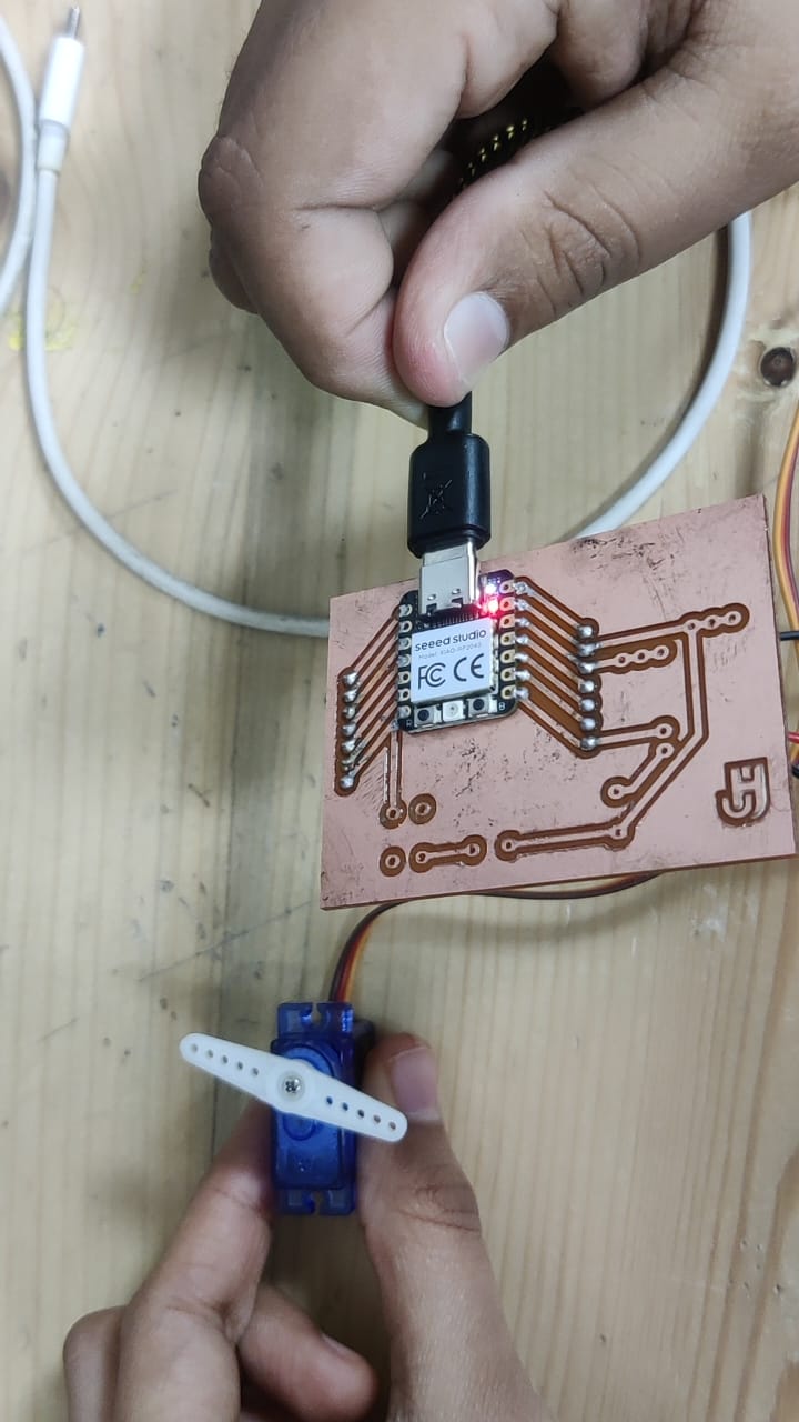
Final Output
To see the video of the servo moving, click below:
Final project pcb
In this week I have also done my final project pcb, imput/ output device both, here is in detail documentation visit my Final Project Page.
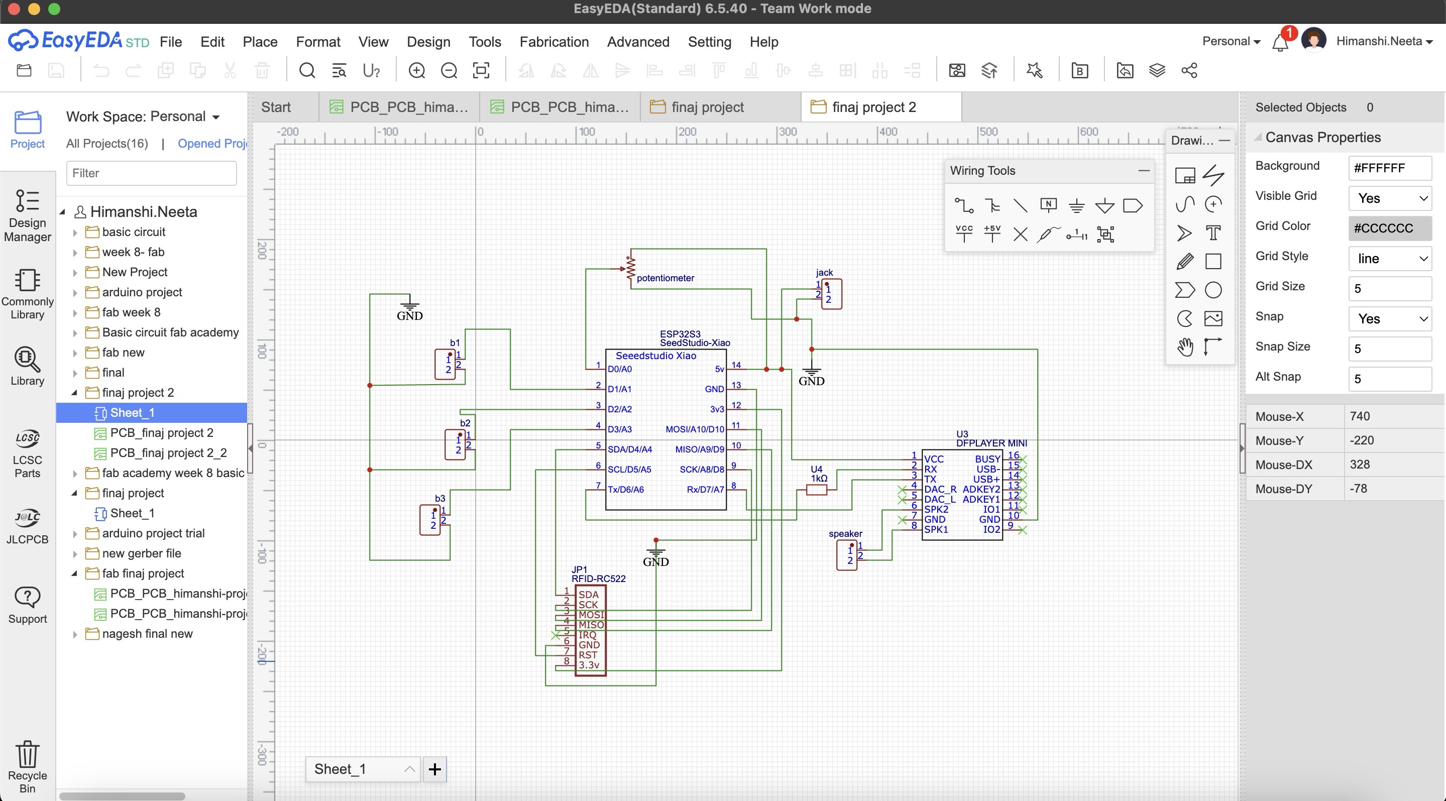
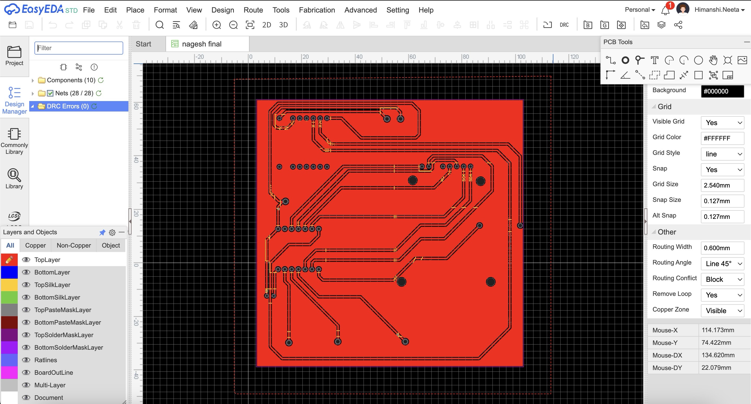
PCB design
After the placement of components were fixed I started with the pcb design. I did the pcb design on easyeda software to know how to use the software go on Week 8- Electronic Design..
Output Components:
The below mentioned components were my output components which I used in my final project pcb.
DF Mini Player:
Function: I used to df mini player to play audio files. It outputs audio signals when triggered by inputs.
Amplifier Speaker:
Function: It amplifies the audio signal from the DF Mini Player and outputs sound.
Steps for making pcb
So step 1 was to make a schematic of the connections by taking components from library and making the connections after that is done save the file and go to convert schematic to pcb in design option which is on the top nav bar.
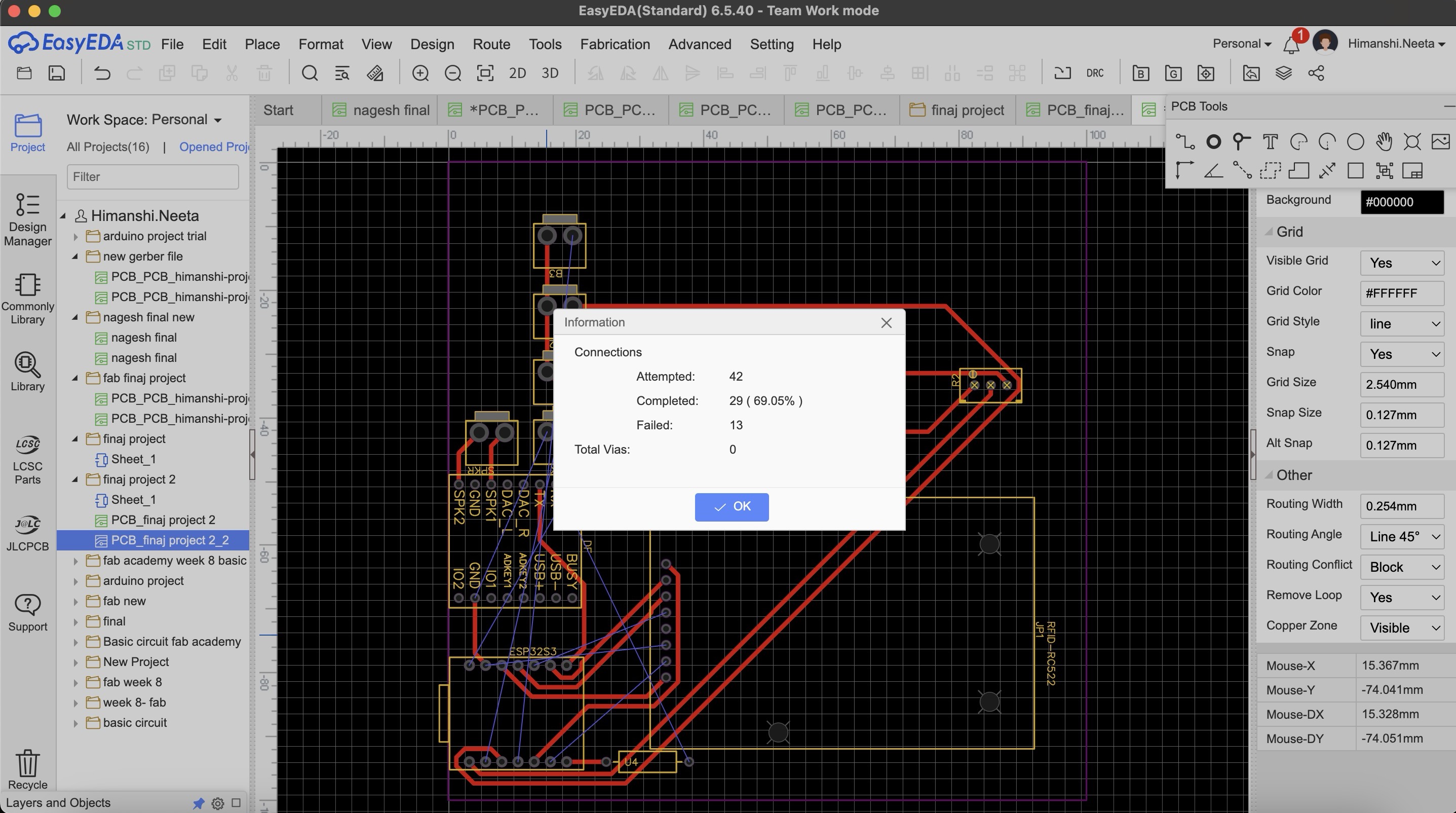
Then I selected the rectangle of 10 by 10cm as we wanted and placed the component how I needed for it to be fit on the case as shown in placing the components parts. I wanted to make a single sided pcb as that is more convinient and easy to use but when I saved my file and did auto routing there were many errors as shown in the image below, the connections were too complicated.
Then I designed double sided pcb and there were no errors.
After designing double sided pcb I realised we don't have the relivent tool for doing double sided pcb so it was not possible for the tools to come as the wait time was long.
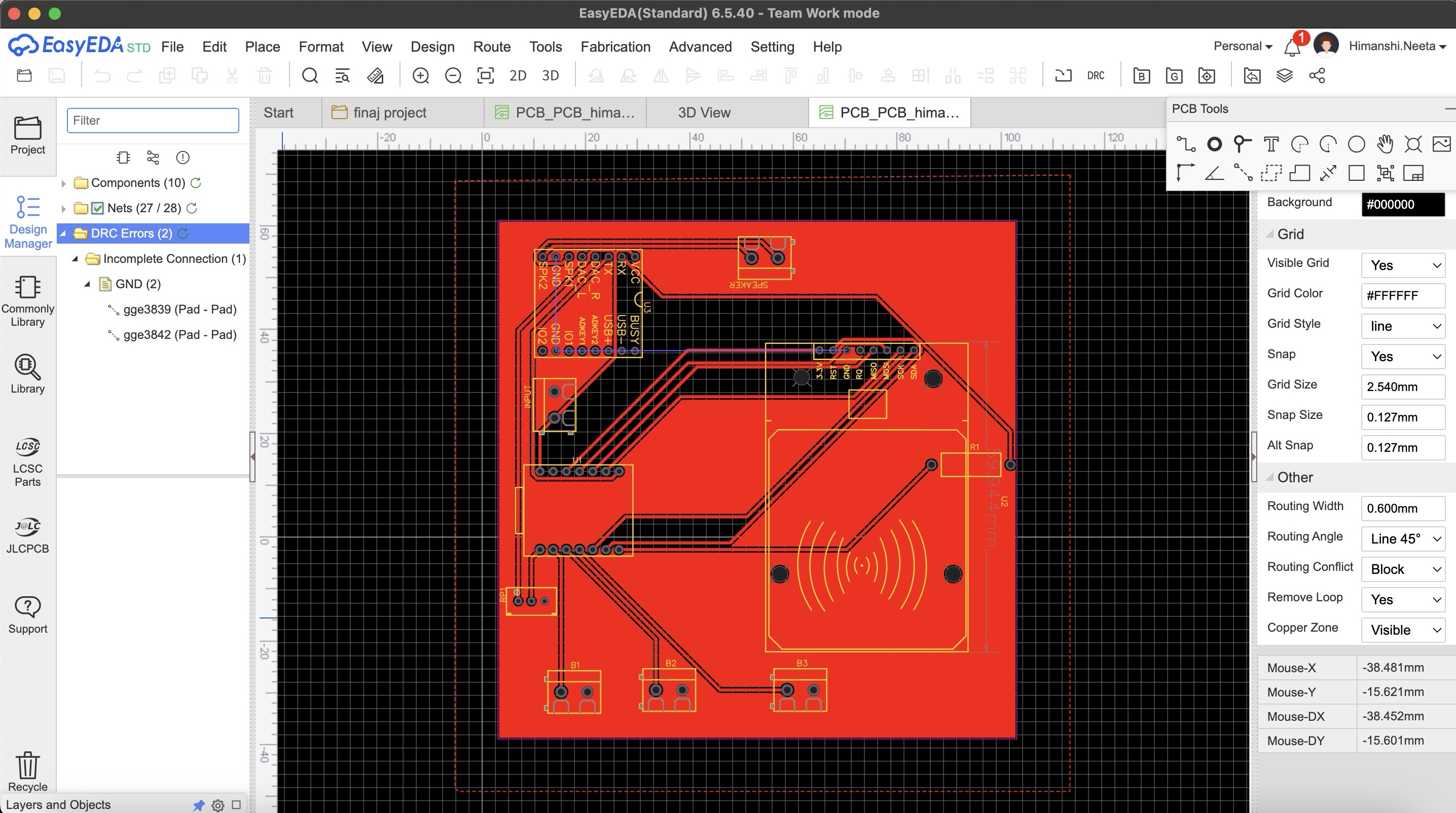
So after this again I did maultiple try and error for single sided pcb and this time I did routing manually as auto routing was failing and then in DRC check there were only 2 errors.
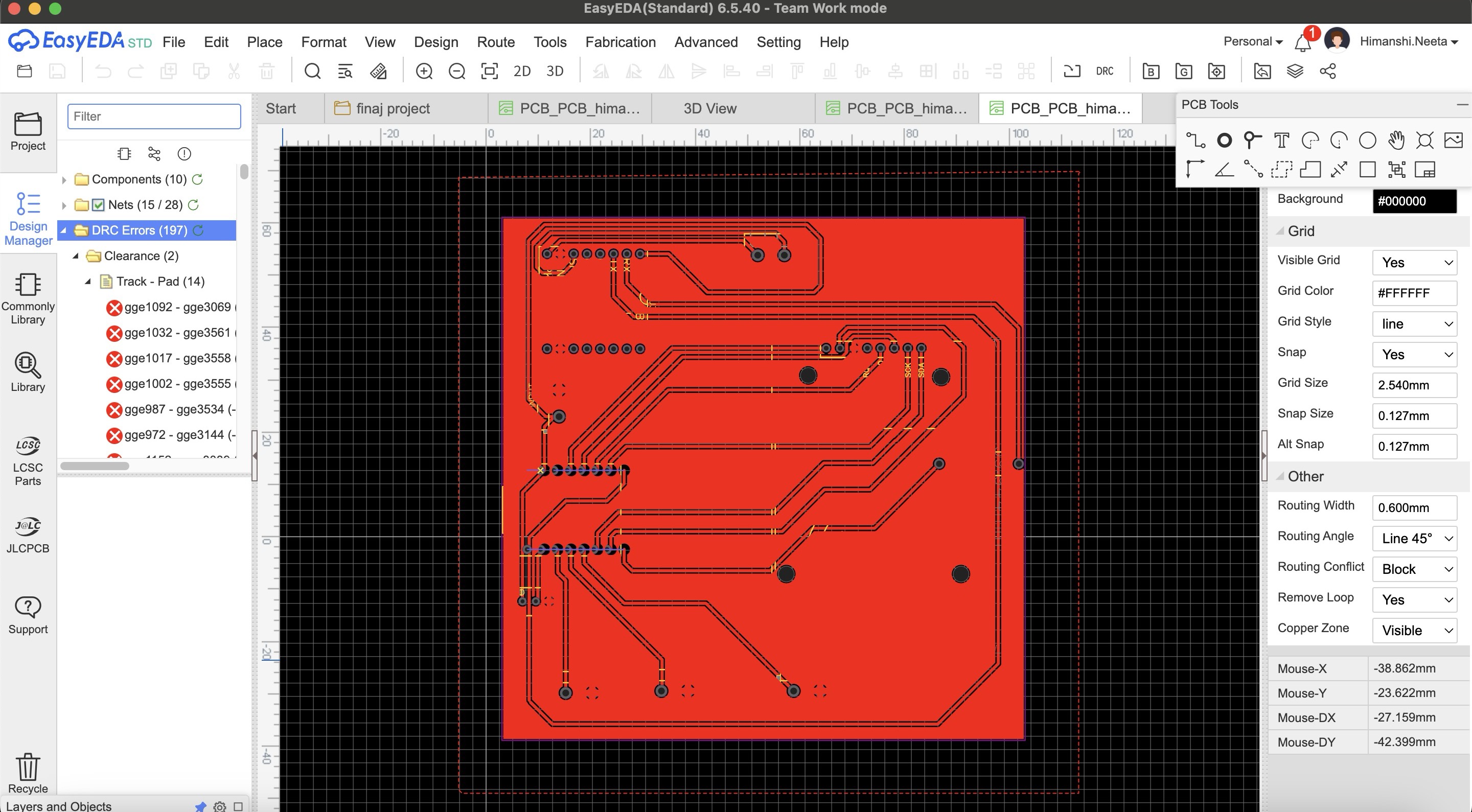
After multiple try and error I got an idea that I'll make common gnd o the entire copper plate, so I designed it accordingly and in the single sided pcb this time again multiple errors as I did auto routing.
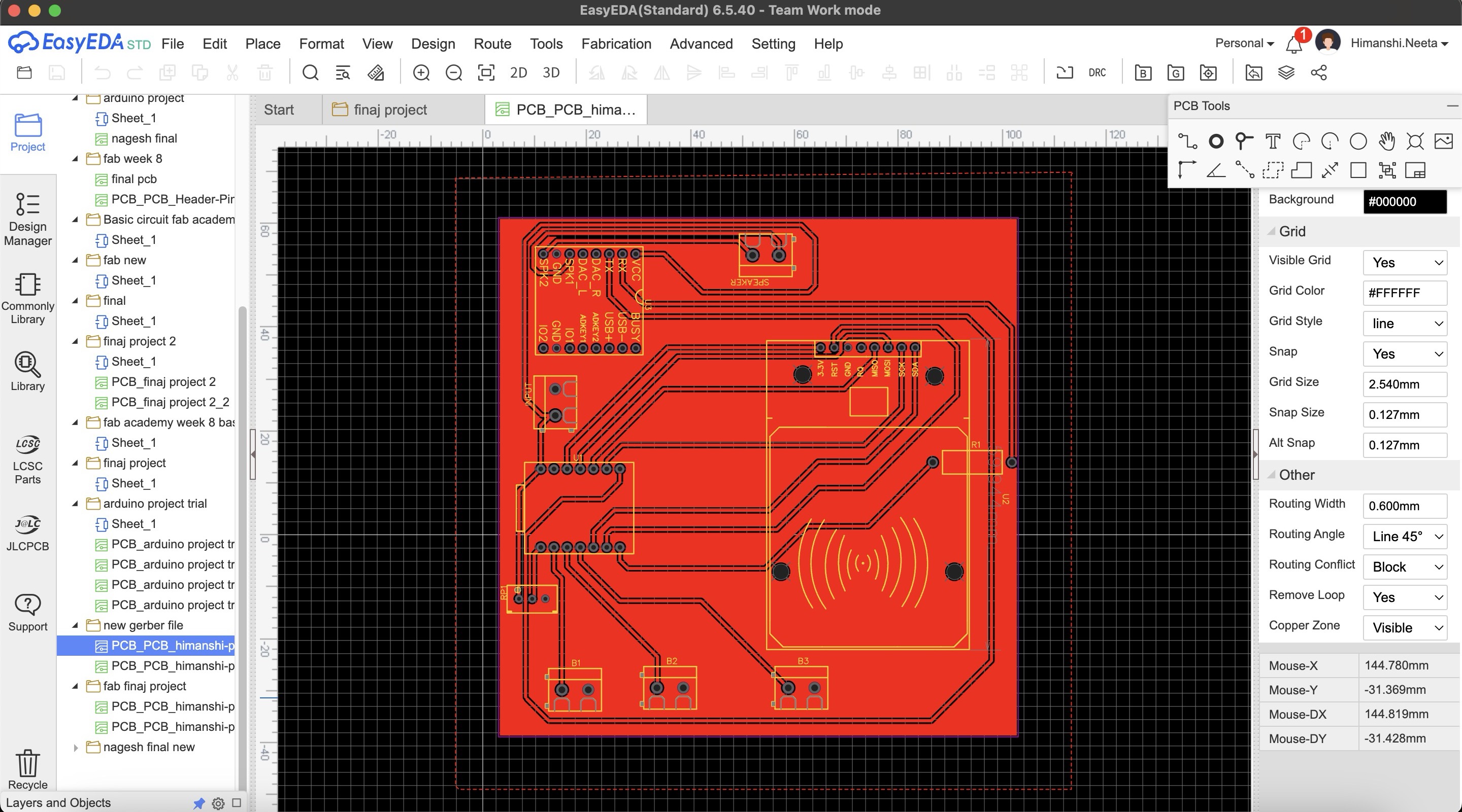
Then I again did the routing manually and finally there were no errors and it is looking perfect now.
PCB Milling
After that I started milling this file, I used SRM20 machine and coppercam software. All the steps of how to use machine and software is mentioned in Week 8- Electronic Production.
Hero Shot
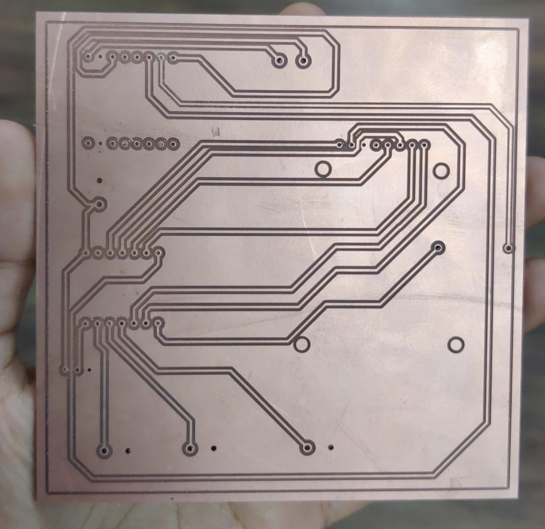
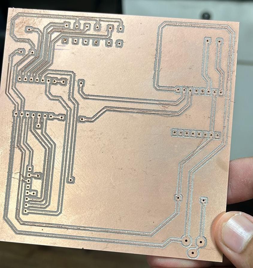
After milling I realised that I should have mirrored the file in copper cam because now the components will be difficult to solder from top, the components should be soldered from below and not from up.
Then I milled a new pcb and in that I mirrored the file
Multimeter testing
After soldering and before soldering too, I tested the connections with the help of multimeter.
Code
What does this code do?
This Arduino code integrates an RFID reader and a DFPlayer Mini MP3 player to create an interactive audio playback system. It uses the MFRC522 RFID module to detect RFID cards and the DFRobotDFPlayerMini library to control the MP3 player. The code initializes the RFID reader and sets up pins for three buttons: start, stop, and pause. When an RFID card is detected, its UID is compared against predefined UIDs stored in an array. If a match is found, the corresponding audio file is played from the MP3 player. The code also reads a potentiometer value to dynamically adjust the volume. Additionally, pressing the start button plays a default audio file, the stop button stops the playback, and the pause button pauses the playback. Debug messages are printed to the serial monitor for monitoring the system's status.
    #include
      #include
      #include

      // RFID RC522 pins
      #define SS_PIN 6
      #define RST_PIN 5

      // Button pins
      #define START_BUTTON_PIN 2
      #define STOP_BUTTON_PIN 3
      #define PAUSE_BUTTON_PIN 4

      MFRC522 mfrc522(SS_PIN, RST_PIN);
      DFRobotDFPlayerMini myDFPlayer;

      // Map RFID card UIDs to sound file numbers
      const byte cardUIDs[10][4] = {
        { 0xE0, 0x14, 0xC6, 0x3B },
        { 0x50, 0x5A, 0x77, 0x59 },
        { 0x43, 0x85, 0x12, 0x50 },
        { 0x93, 0xDB, 0x02, 0xE4 },
        { 0x24, 0xAE, 0xD0, 0x09 },
        { 0xD3, 0xA0, 0x67, 0x1A },
        { 0xD3, 0xA0, 0x67, 0x1A },
        { 0xE3, 0x2B, 0xA2, 0xE4 },
        { 0x43, 0x75, 0xAD, 0xE4 },
        { 0xC3, 0x80, 0x50, 0x1D }
      };

      void setup() {
        Serial.begin(9600);  // Initialize hardware serial for DFPlayer Mini at 9600 baud
        Serial1.begin(9600, SERIAL_8N1, 44, 43);
        SPI.begin();         // Init SPI bus
        mfrc522.PCD_Init();  // Init MFRC522

        pinMode(START_BUTTON_PIN, INPUT_PULLUP);
        pinMode(STOP_BUTTON_PIN, INPUT_PULLUP);
        pinMode(PAUSE_BUTTON_PIN, INPUT_PULLUP);
        pinMode(1,INPUT_PULLUP);
        if (!myDFPlayer.begin(Serial1)) {
          Serial.println(F("Unable to begin:"));
          Serial.println(F("1.Please recheck the connection!"));
          Serial.println(F("2.Please insert the SD card!"));
          while (true)
            ;
        }
        myDFPlayer.volume(30);  // Set volume value (0~30).

        Serial.println(F("Place your RFID card near the reader..."));
      }

      void loop() {
        int potValue = analogRead(1);

        int vol = map(potValue, 0, 4096, 0, 30);
        vol = constrain(vol,0,30);
        myDFPlayer.volume(vol);
        Serial.println("Volume: "+String(vol));
        Serial.println("Button Start: " + String(digitalRead(START_BUTTON_PIN)));
        Serial.println("Button Stop: " + String(digitalRead(STOP_BUTTON_PIN)));
        Serial.println("Button Pause: " + String(digitalRead(PAUSE_BUTTON_PIN)));
        // Check for button presses
        if (digitalRead(START_BUTTON_PIN) == LOW) {
          myDFPlayer.play(1);  // Play a default audio file (e.g., 0001.mp3)
          Serial.println("Start button pressed, playing default audio.");
          delay(300);  // Debounce delay
        }

        if (digitalRead(STOP_BUTTON_PIN) == LOW) {
          myDFPlayer.stop();
          Serial.println("Stop button pressed, stopping audio.");
          delay(300);  // Debounce delay
        }

        if (digitalRead(PAUSE_BUTTON_PIN) == LOW) {
          myDFPlayer.pause();
          Serial.println("Pause button pressed, pausing audio.");
          delay(300);  // Debounce delay
        }

        // RFID code
        if (mfrc522.PICC_IsNewCardPresent() && mfrc522.PICC_ReadCardSerial()) {
          // Print Card UID in the desired format
          Serial.print("{");
          for (byte i = 0; i < mfrc522.uid.size; i++) {
            Serial.print("0x");
            Serial.print(mfrc522.uid.uidByte[i], HEX);
            if (i < mfrc522.uid.size - 1) {
              Serial.print(", ");
            }
          }
          Serial.println("}");

          // Compare the read UID with the predefined UIDs
          for (int i = 0; i < 10; i++) {
            if (memcmp(mfrc522.uid.uidByte, cardUIDs[i], 4) == 0) {
              Serial.print("Playing sound for card ");
              Serial.println(i + 1);
              myDFPlayer.play(i + 1);  // Play the corresponding MP3 file (files should be named 0001.mp3, 0002.mp3, etc.)
              break;
            }
          }

          delay(1000);
        }
        delay(100);
      }
HeroShot of PCB
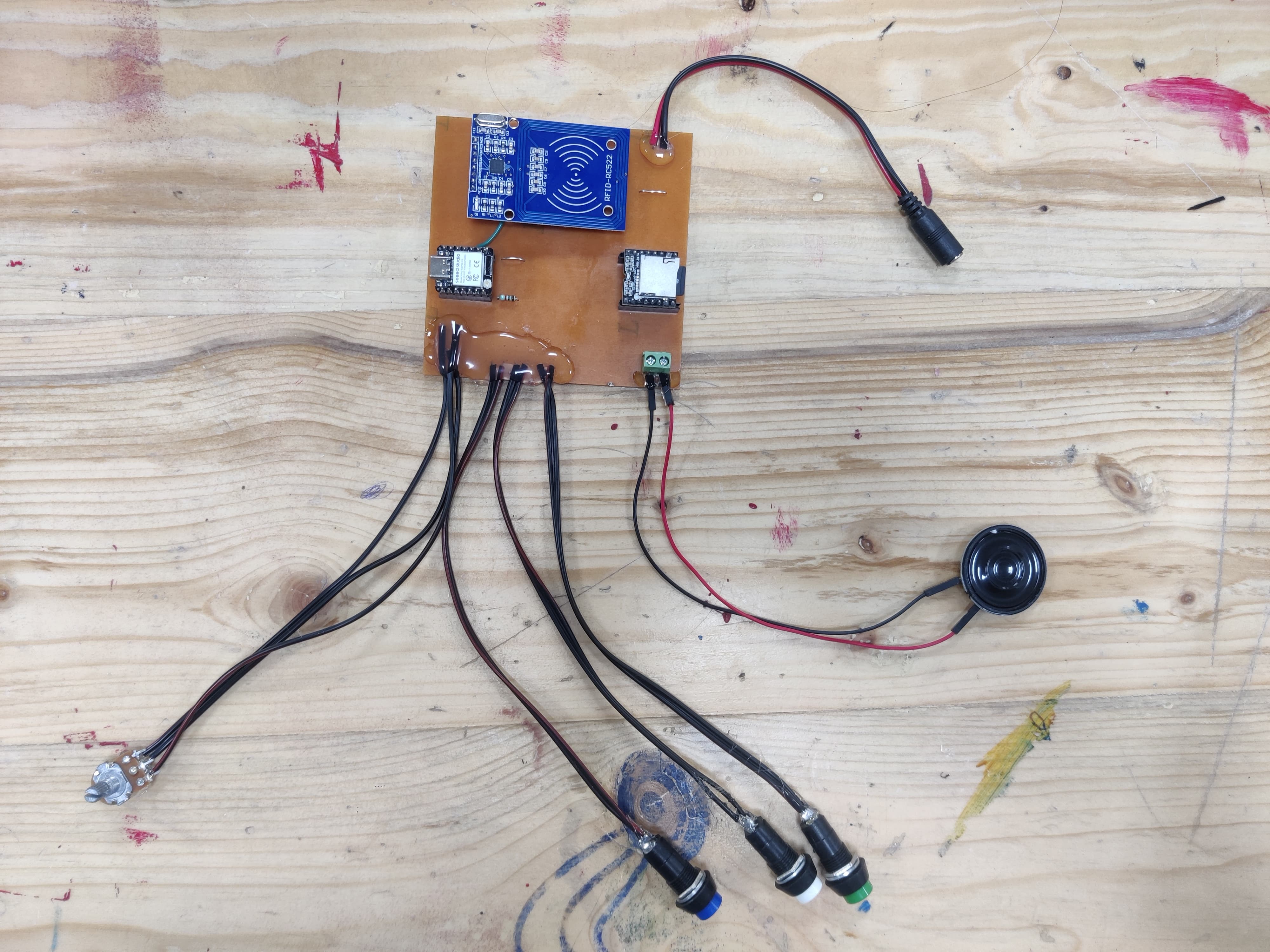
WOrking of PCB
After that I made the design for pcb and milled it and tried out the circuit on that.
Conclusion from this week
During Output Devices Week, the assignments focused on integrating and measuring output devices with microcontroller boards. Individually, I added a servo motor to a microcontroller board using the RP2040 Seed Studio Xiao chip. I successfully programmed it to rotate upon running the code. As a group, we measured the power consumption of the output device. This week provided practical experience in enhancing microcontroller functionality with output devices and understanding their power requirements.
Design Files
Image Credits
All images of cover page are credited below:
https://images.app.goo.gl/RpsW279obzc9qcq66
https://images.app.goo.gl/LW3qLSMu5sjD2m7TA
https://images.app.goo.gl/ajX5e4P2g8V81oUv7
https://images.app.goo.gl/mq2usFoJ7rezPbdz7
https://images.app.goo.gl/Fmjkmf27f6ta1VKK8
https://images.app.goo.gl/rHhhNb9XJYB9okKE7
https://images.app.goo.gl/qdqj7QpURTZfiETg7
https://images.app.goo.gl/wkVfs6jJfYpjM2Do7
https://images.app.goo.gl/aH2TMFxyg5Y22rnL8
https://images.app.goo.gl/cbddio8wea3mdHvY7
https://images.app.goo.gl/aBEQazreUXMHpEDA8