Computer Controlled Machining
Computer-controlled machining, often referred to as CNC (Computer Numerical Control) machining, is a manufacturing process where computer software controls the movement and operation of machine tools and equipment. This process enables precise and automated fabrication of parts and components from various materials such as metal, plastic, wood, and composites. CNC machines use programmed instructions to dictate the movement of cutting tools along multiple axes, allowing for intricate and complex shapes to be produced with high accuracy and repeatability. Common CNC machining operations include milling, turning, drilling, and grinding, and it finds applications across industries such as automotive, aerospace, electronics, and prototyping.
This week's assignment is to make something big (~meter-scale) and (design+mill+assemble) it.
What is CNC Machine?
A CNC (Computer Numerical Control) machine is a computer-controlled manufacturing device that operates machine tools and equipment with precision and automation. CNC machines use programmed instructions to control the movement of cutting tools and workpieces, allowing for the accurate fabrication of parts and components.
Types of CNC Machine
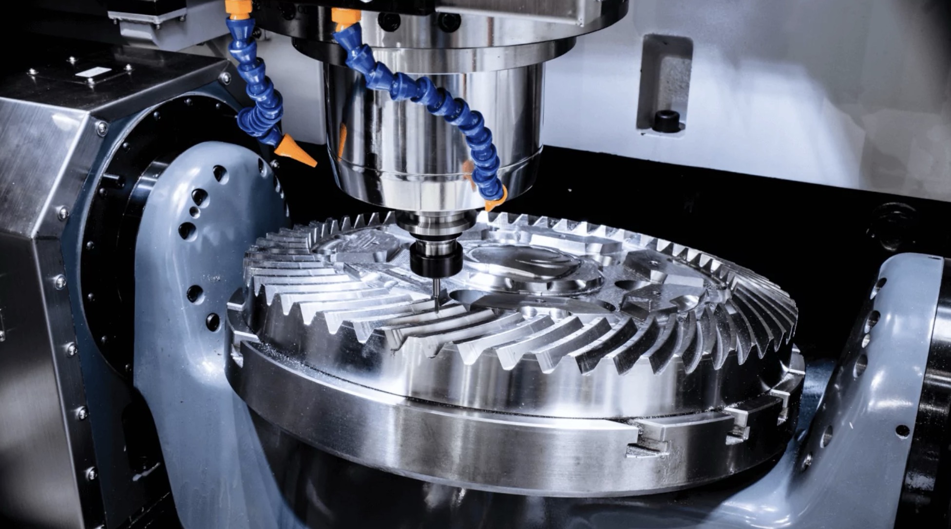
1. CNC Milling Machine:
These machines use rotary cutting tools to remove material from a workpiece, producing complex shapes and features. They can perform operations such as drilling, tapping, and contouring in multiple axes.
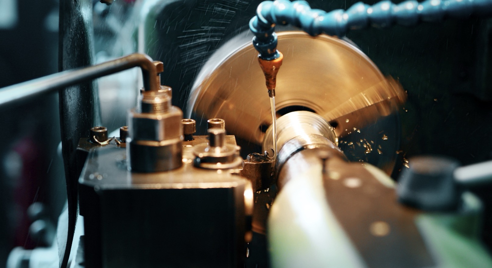
2. CNC Lathe Machine:
Also known as CNC turning machines, these devices rotate the workpiece while stationary cutting tools shape it into cylindrical or conical shapes. CNC lathes are commonly used for producing shafts, bolts, and other rotating parts.
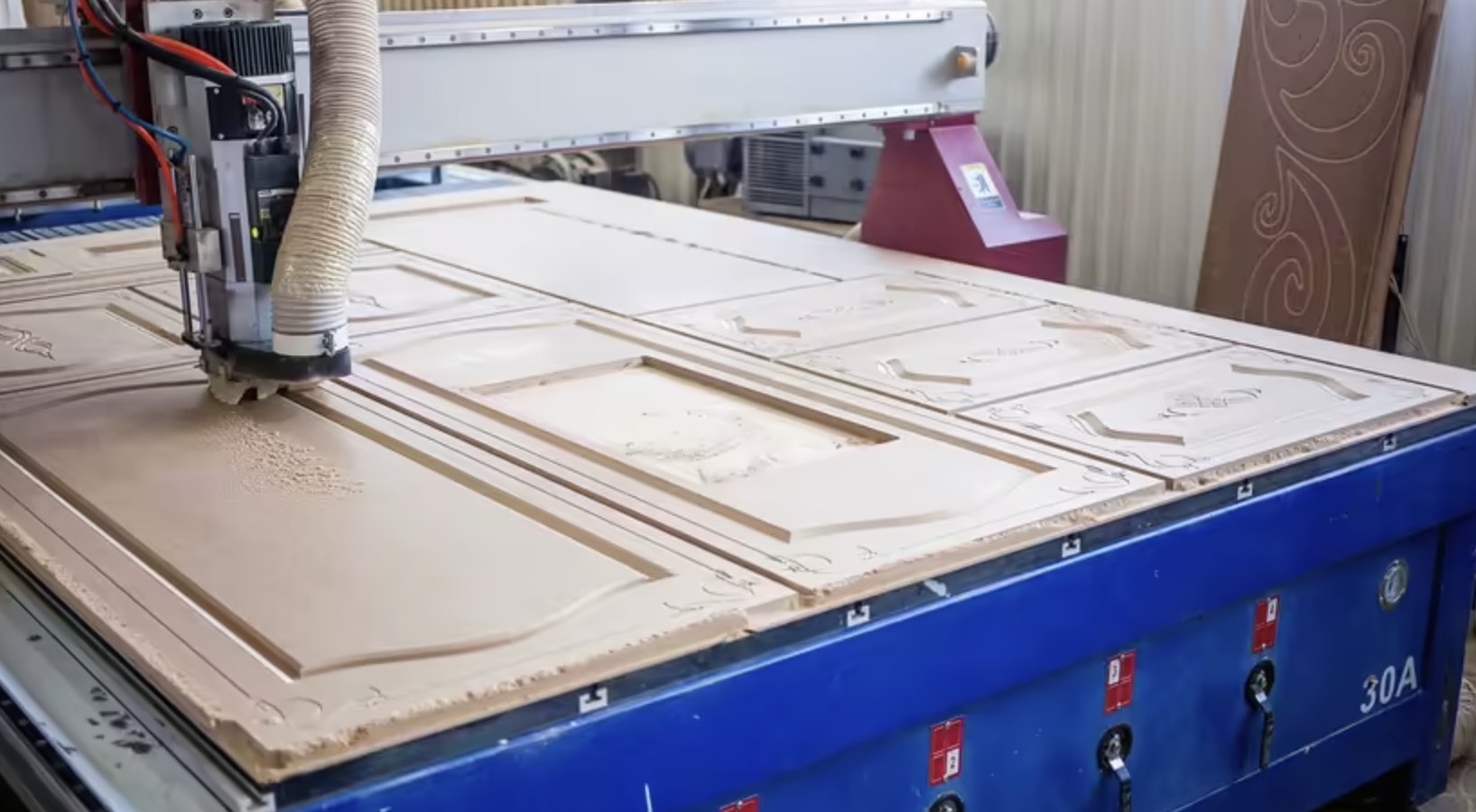
3. CNC Router:
Similar to milling machines, CNC routers use rotating cutting tools to carve and shape materials such as wood, plastic, and foam. They are popular in woodworking, signage, and prototyping industries.
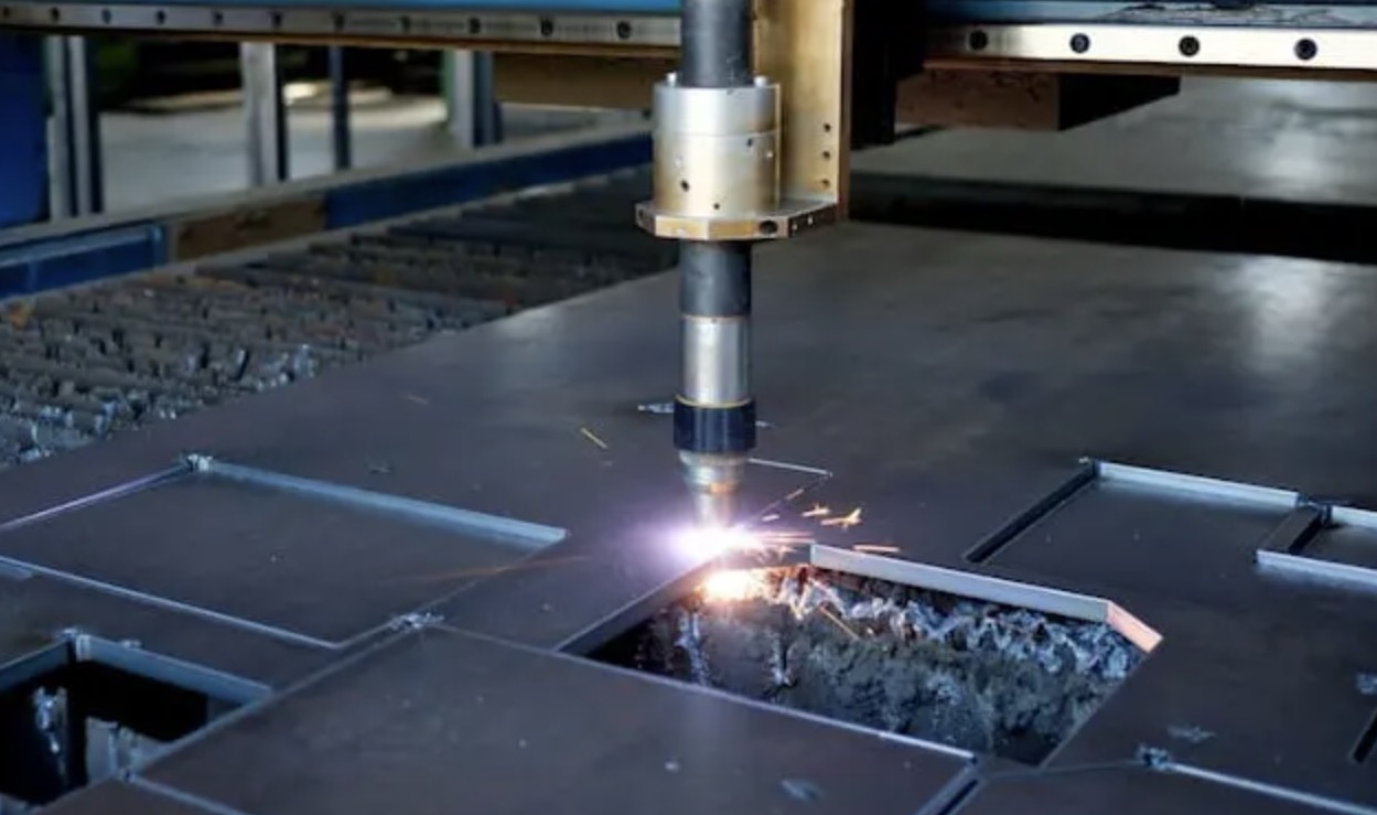
4. CNC Plasma Cutter:
These machines use a high-velocity jet of ionized gas (plasma) to cut through electrically conductive materials such as steel, aluminum, and brass. CNC plasma cutters are widely used in metal fabrication and construction.
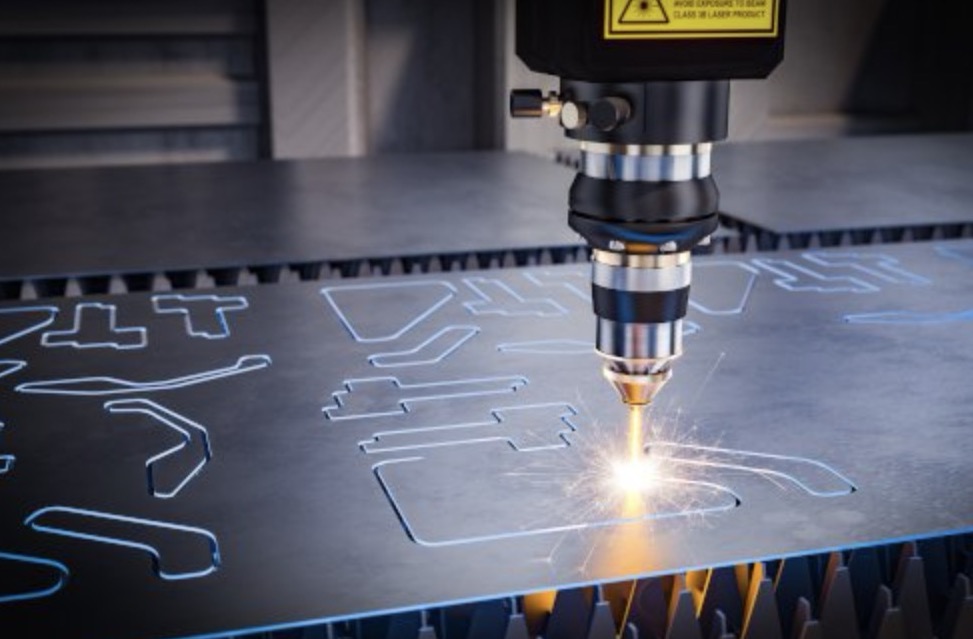
5. CNC Laser Cutter:
Laser cutting machines utilize a focused laser beam to melt, burn, or vaporize material, creating precise cuts with minimal heat-affected zones. They are suitable for cutting various materials, including metal, plastic, and fabric.
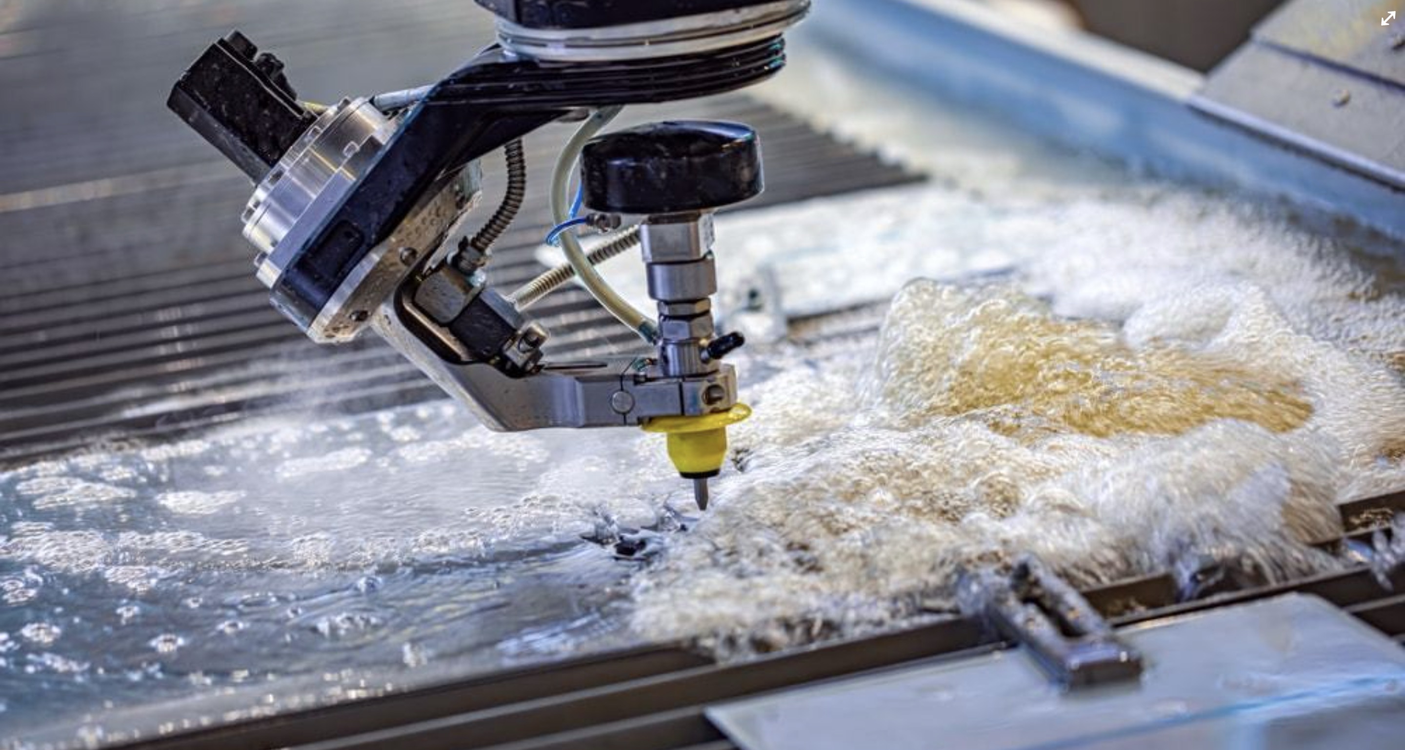
6. CNC Waterjet Cutter:
Waterjet cutting machines use a high-pressure stream of water mixed with abrasive particles to cut through materials. CNC waterjets are versatile and can handle a wide range of materials, including metals, ceramics, and composites.
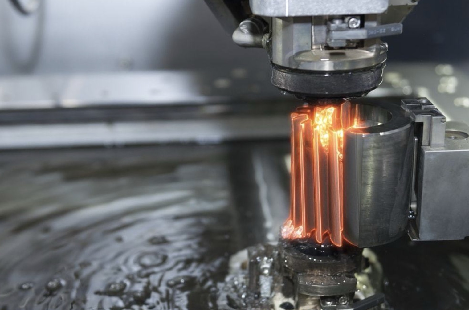
7. CNC EDM (Electrical Discharge Machining):
EDM machines use electrical discharges to remove material from a workpiece. They are commonly used for machining complex shapes and hardened materials that are difficult to machine with conventional methods.
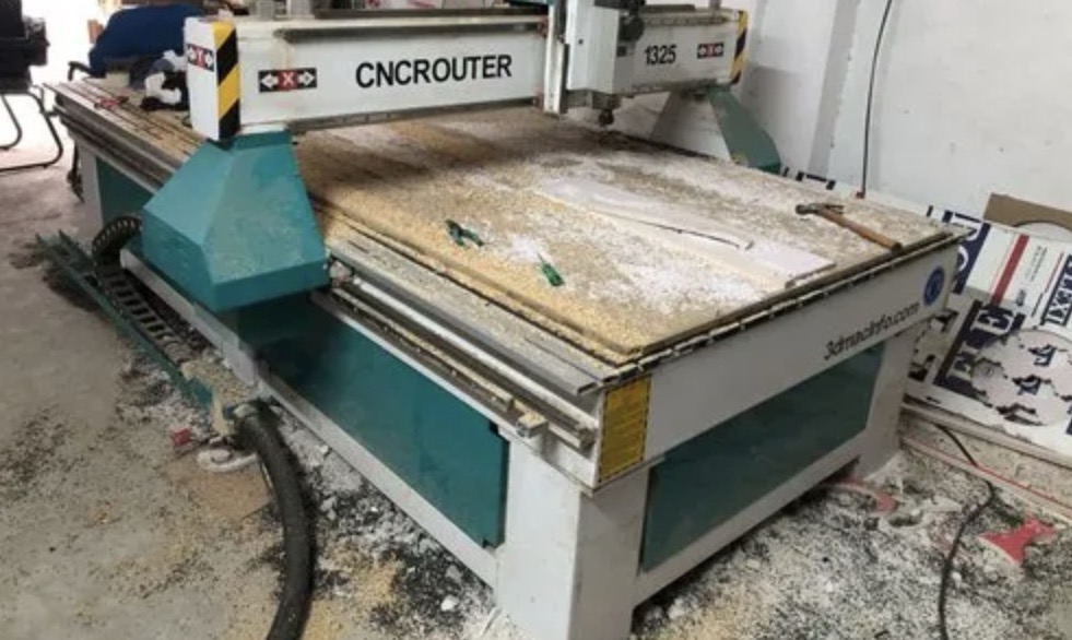
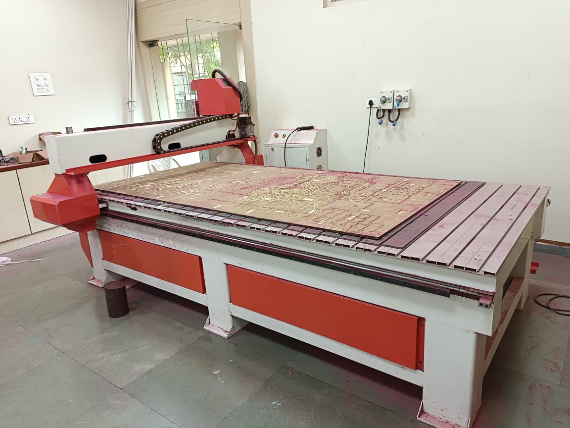
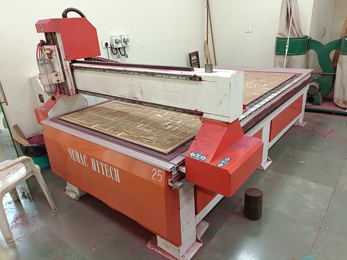
The CNC Router
The machine we have is a Numac Hitech machine with a full sized 8' x 4' i.e. 2400 mm x 1200 mm bed size, able to accommodate the standard full size sheets available here.
The CNC router comprises three main components:
1. Base
2. Control unit
3. Ventilation system
Group Work
Test runout, alignment, fixturing, speeds, feeds, materials and toolpaths for your machine this part of group work is uploaded on Siddhart's Page and safety instructions is uploaded on my page below.
Learnings
During Computer Controlling Machine Week, I gained practical skills in using a CNC router, particularly in furniture making. Completing the lab's safety training emphasized the importance of safety protocols and proper use of PPE. I learned the significance of precision in testing runout and alignment to ensure accurate machining. Understanding fixturing techniques taught me how to secure workpieces properly to prevent movement during cutting. Exploring speeds and feeds helped me optimize the machining process based on material properties, reducing tool wear and achieving desired finishes. Working with various materials gave me insights into their unique characteristics and how they affect machining. Designing and testing toolpaths using CAD/CAM software highlighted the importance of planning and verifying to prevent errors and achieve precise results. Overall, this week enhanced my technical skills and understanding of CNC routing and machining processes.
Safety instructions for using the CNC router
1. Safety goggles should be worn at all times in operational zones.
2. Wear a mask when excessive dust or hazardous fumes are present.
3. Avoid wearing rings and jewelry near moving machine parts.
4. Tie back or secure long hair to prevent entanglement.
5. Wear close-fitting protective clothing or a workshop apron.
6. Wear sturdy footwear with reinforced uppers.
7. Familiarize yourself with the ON/OFF and emergency stop controls.
8. Ensure the waste collector shroud and coolant system are properly adjusted for optimal performance.
Assignment- Making something big
"Making something big" assignment, I have decided to make center table for my house as we need one. The steps from ideating to actually assembling it together are explained below in detail:
Step 01: Ideation
Center table is the thing which is mostly in the living room ans should amtch the aesthetic of the room and the size should also be dependent on that, keeping all this in mind I started ideating and sketching for tables.
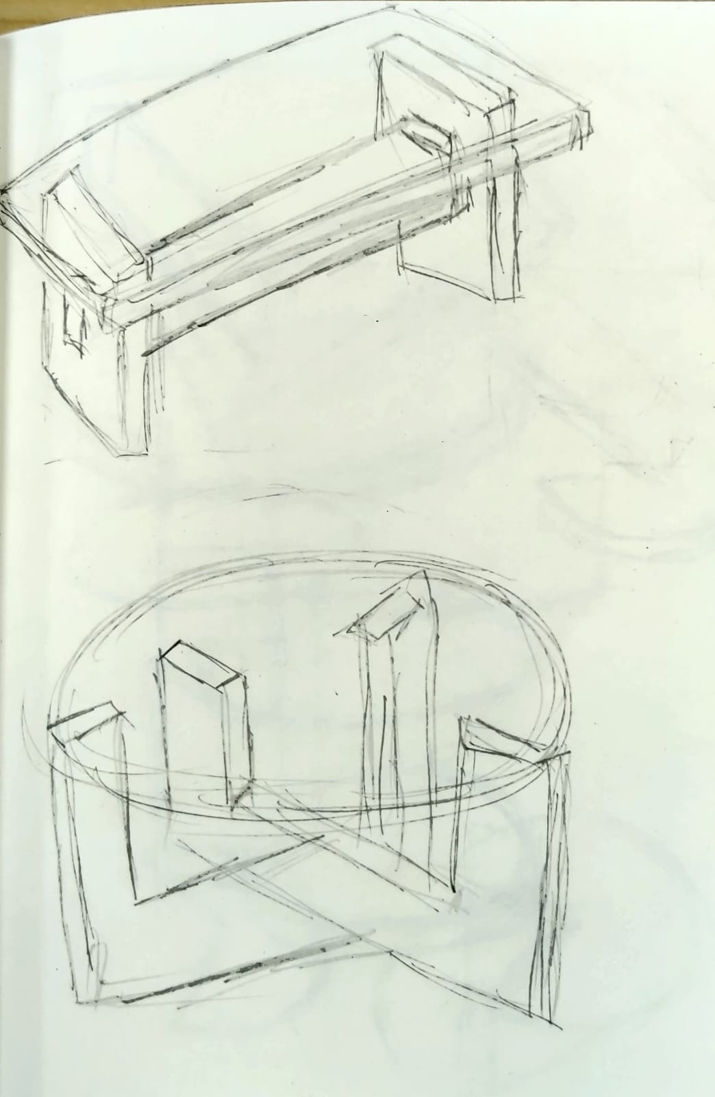
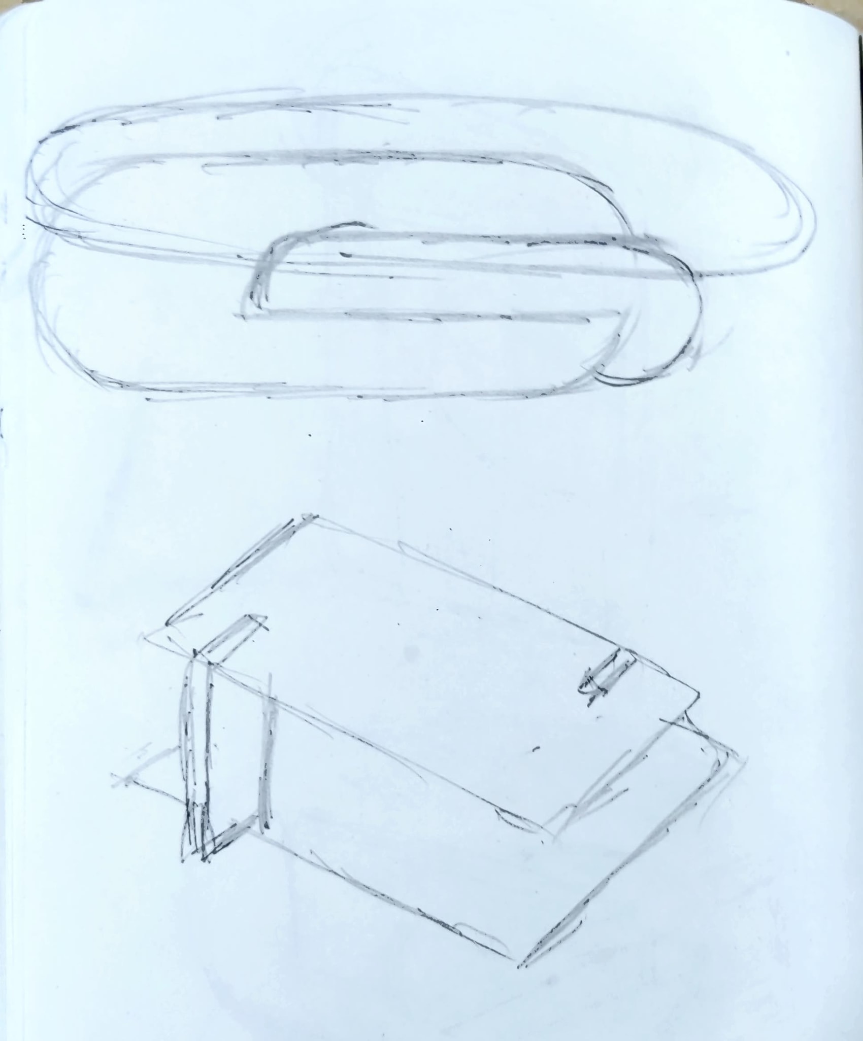
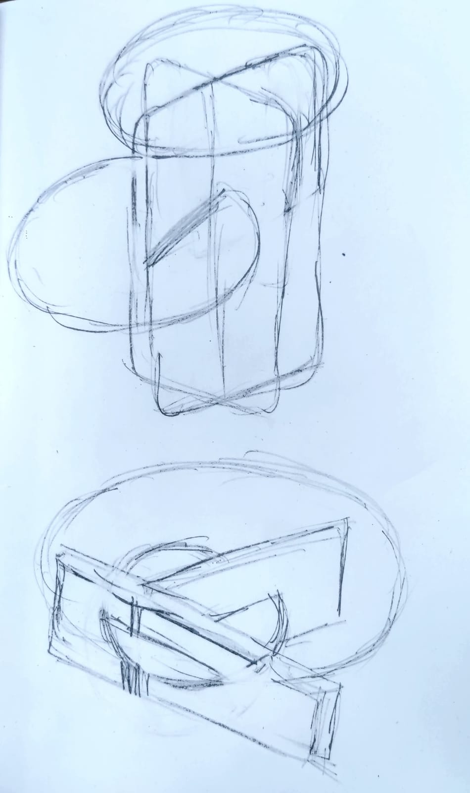
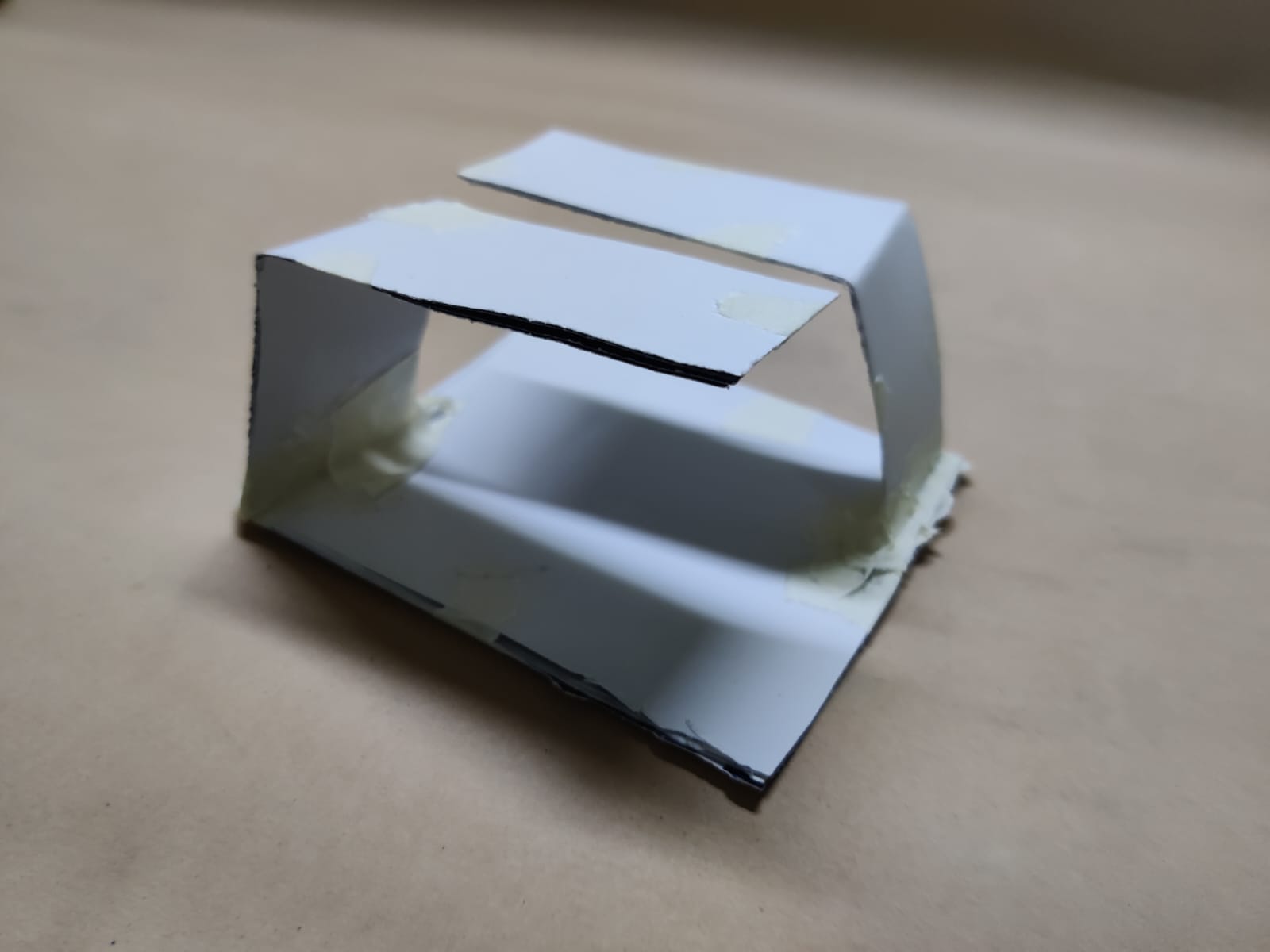
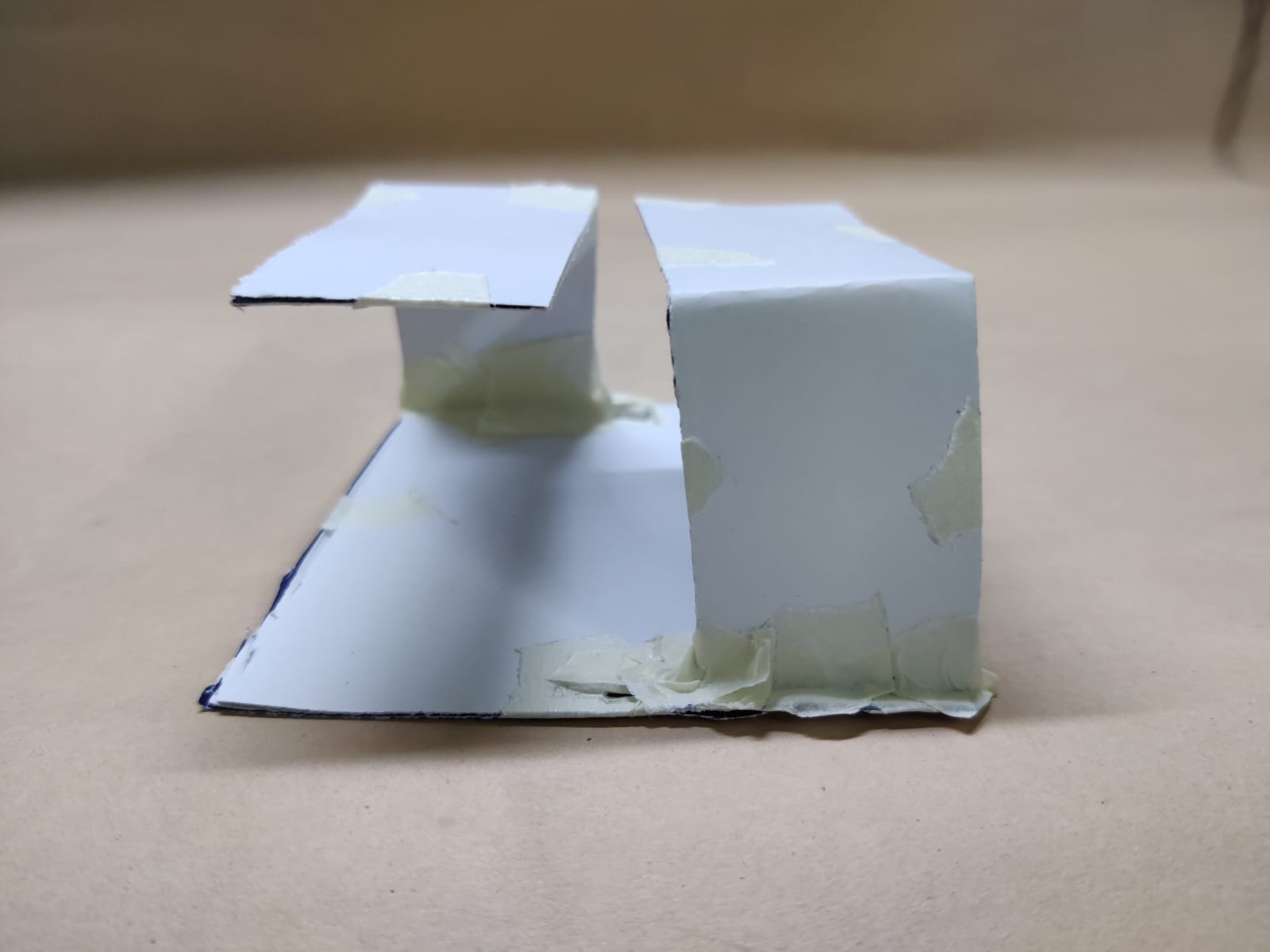
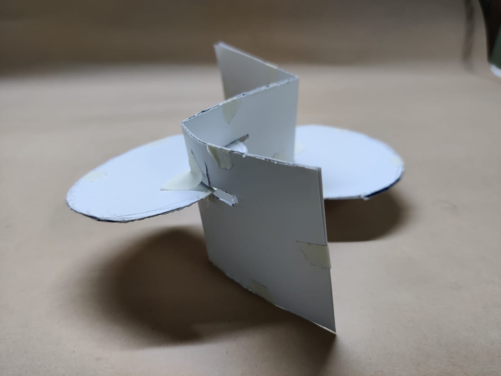
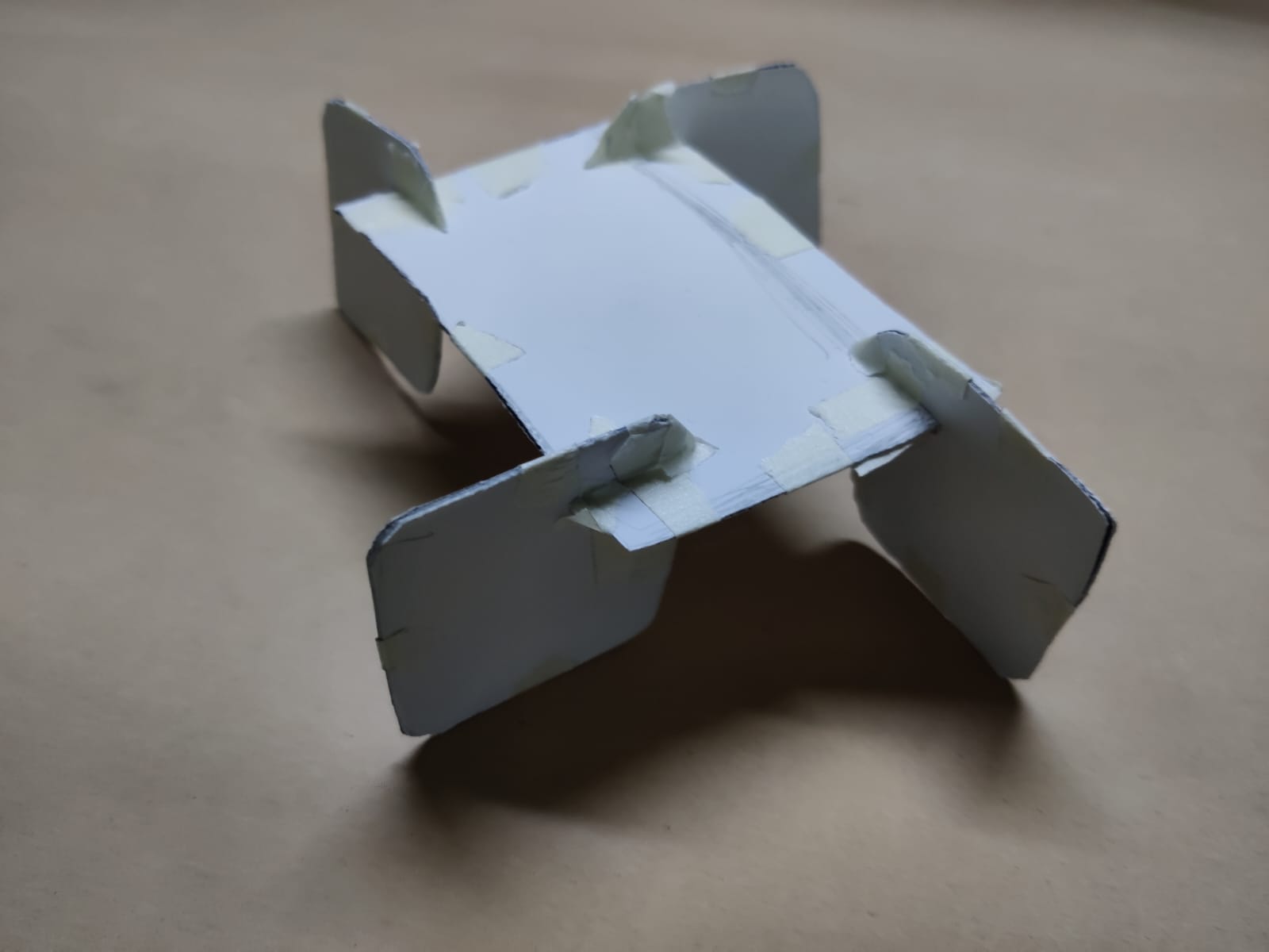
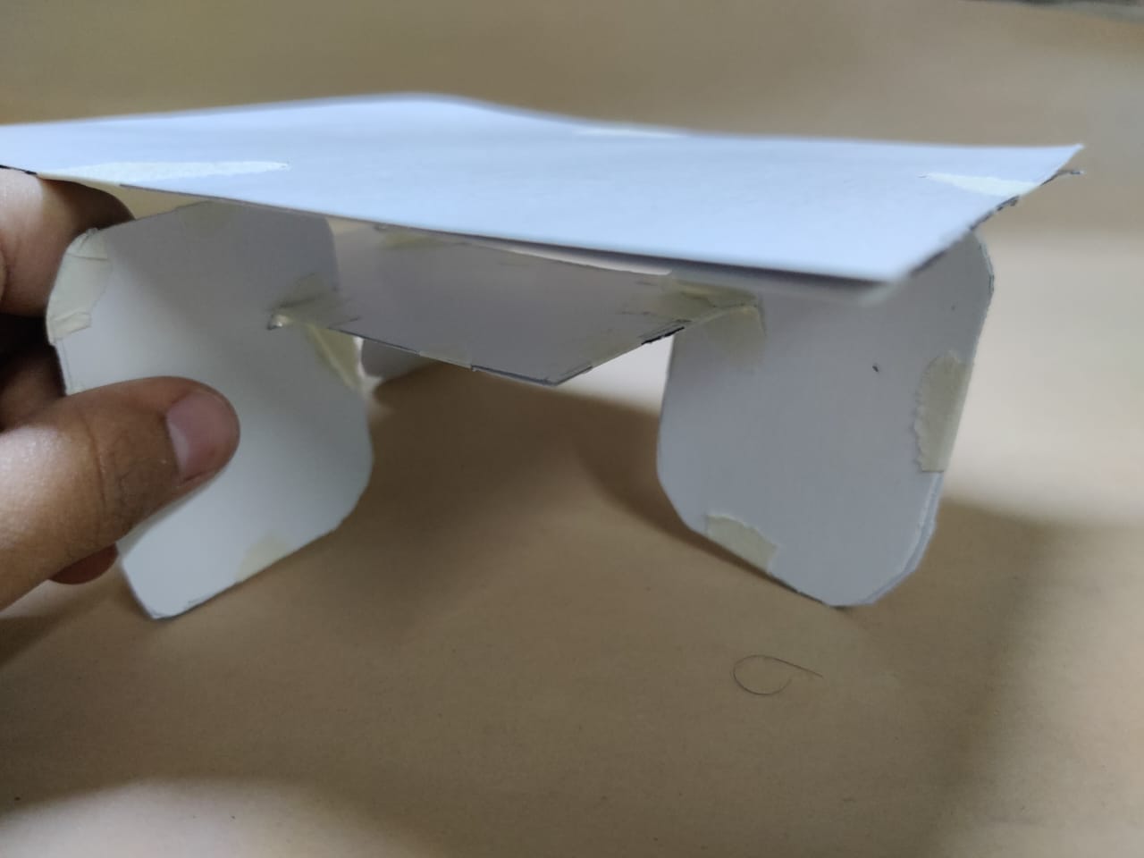
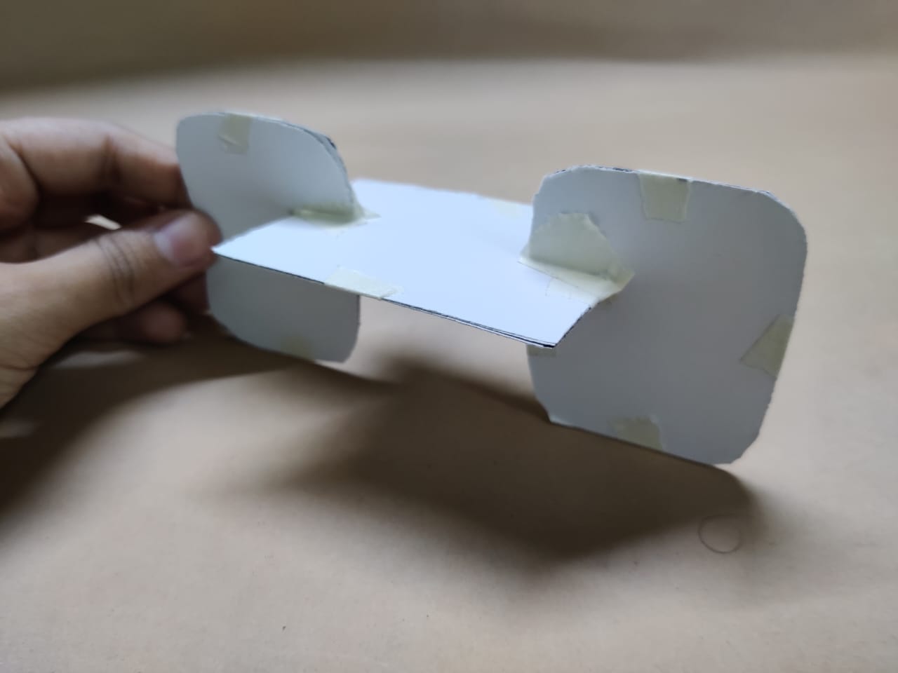
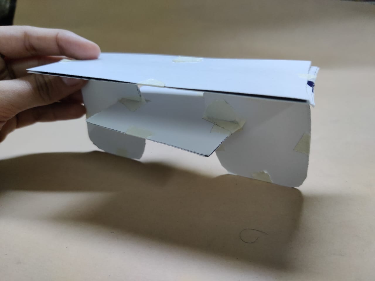
Step 02: Prototypes
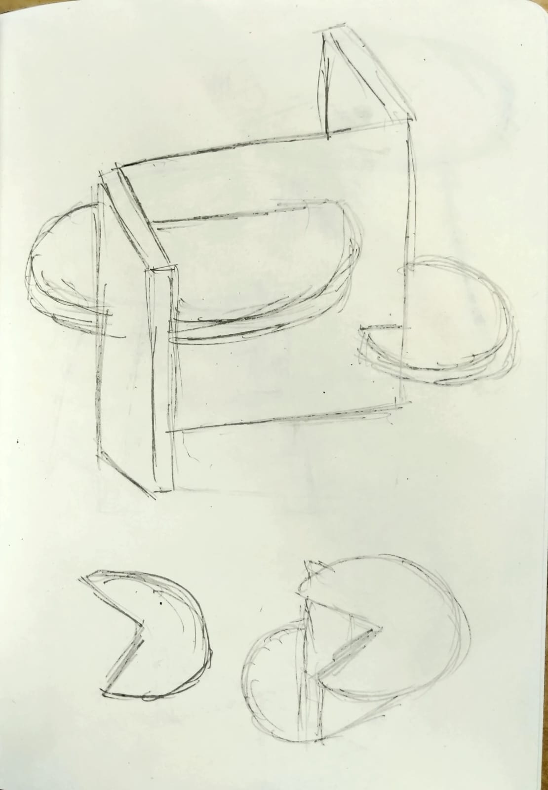
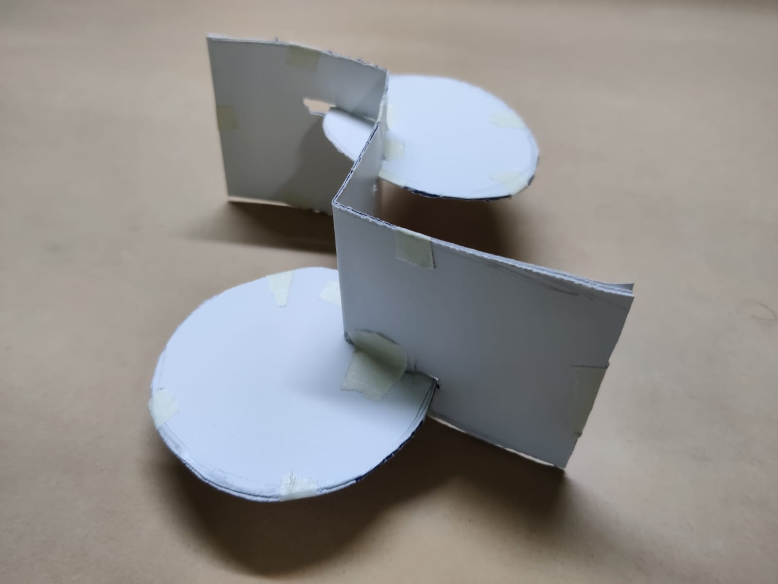
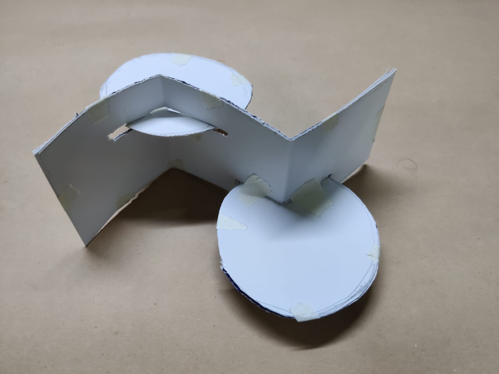
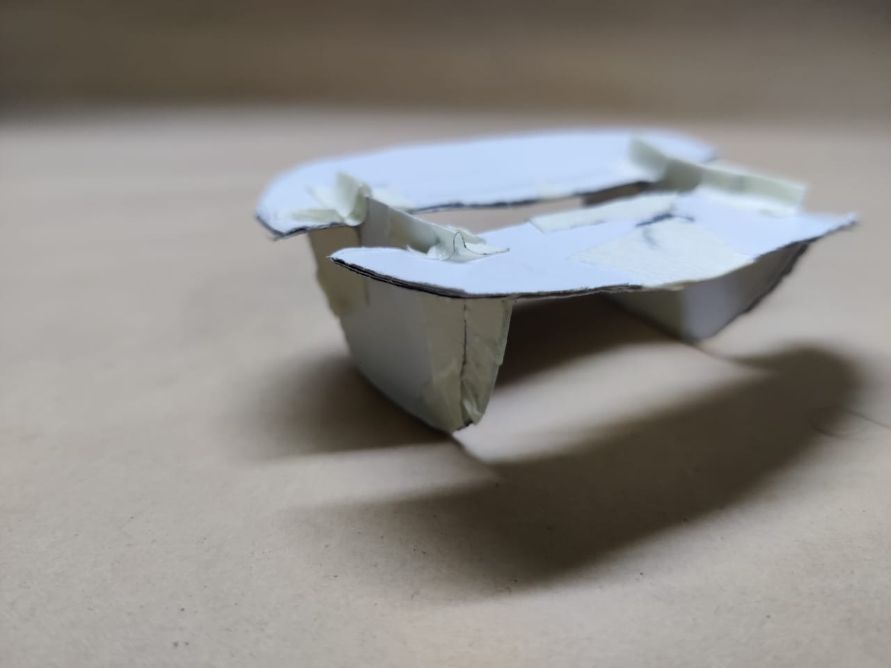
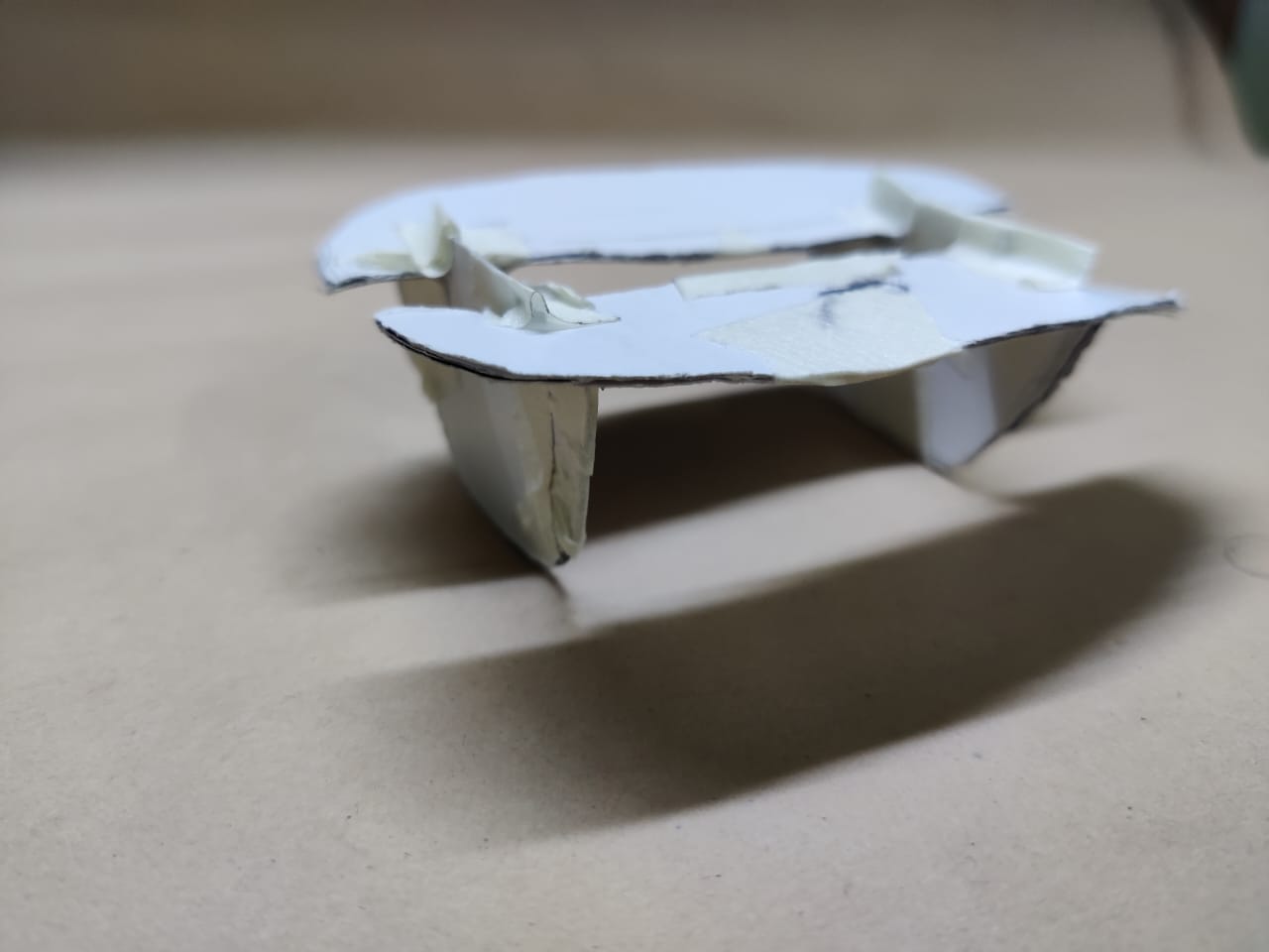
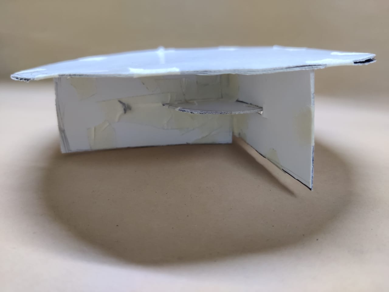
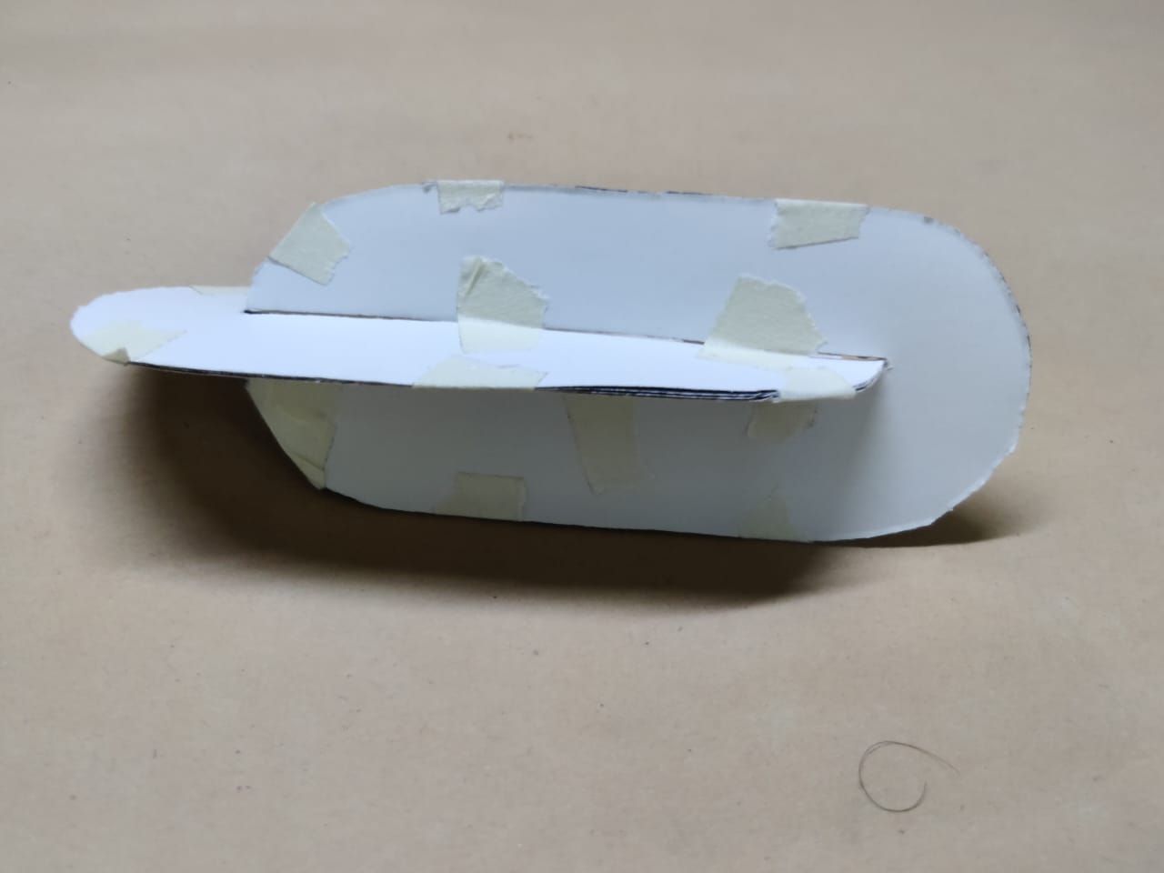
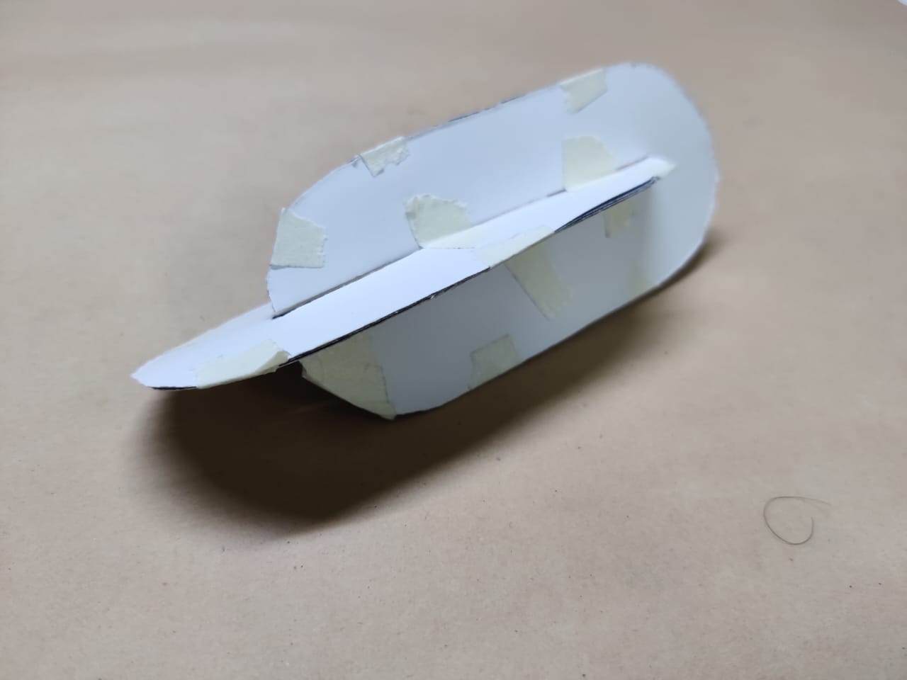
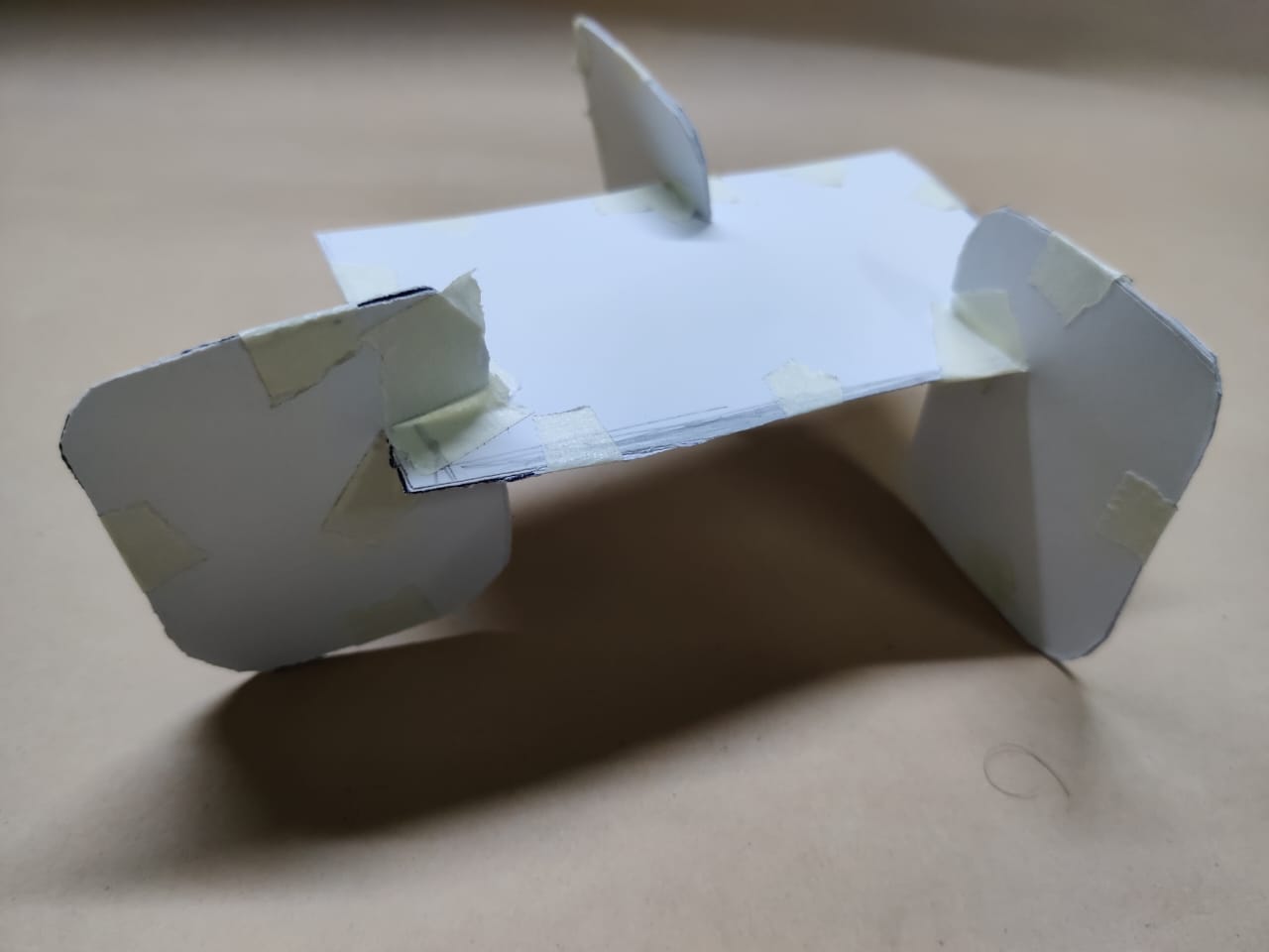
I had many ideas more but I am not that good at sketching, so I decided making quick paper prototypes will be much faster and easier. I was travelling this weekend so I made prototype with whatever possible material I had. Below are my design:
Design 1
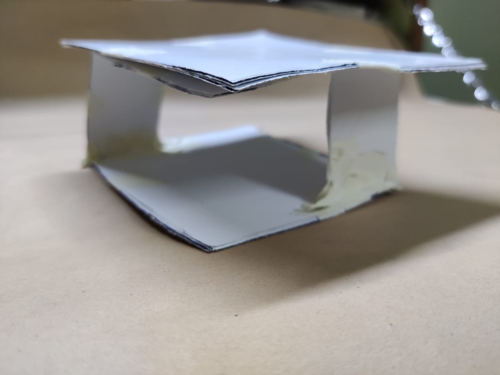
After making this design I realised that this design can be made upside down by removing the top rectangle.
Design 2
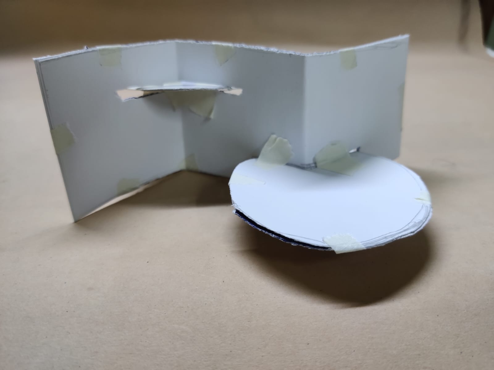
Design 3
Design 4
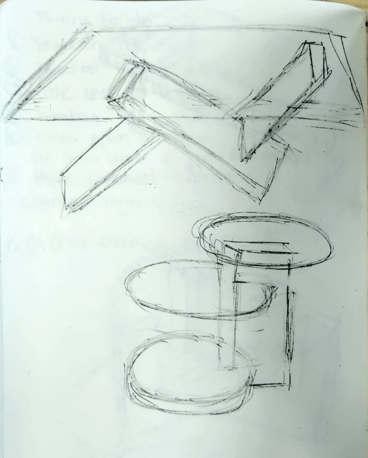
Design 5
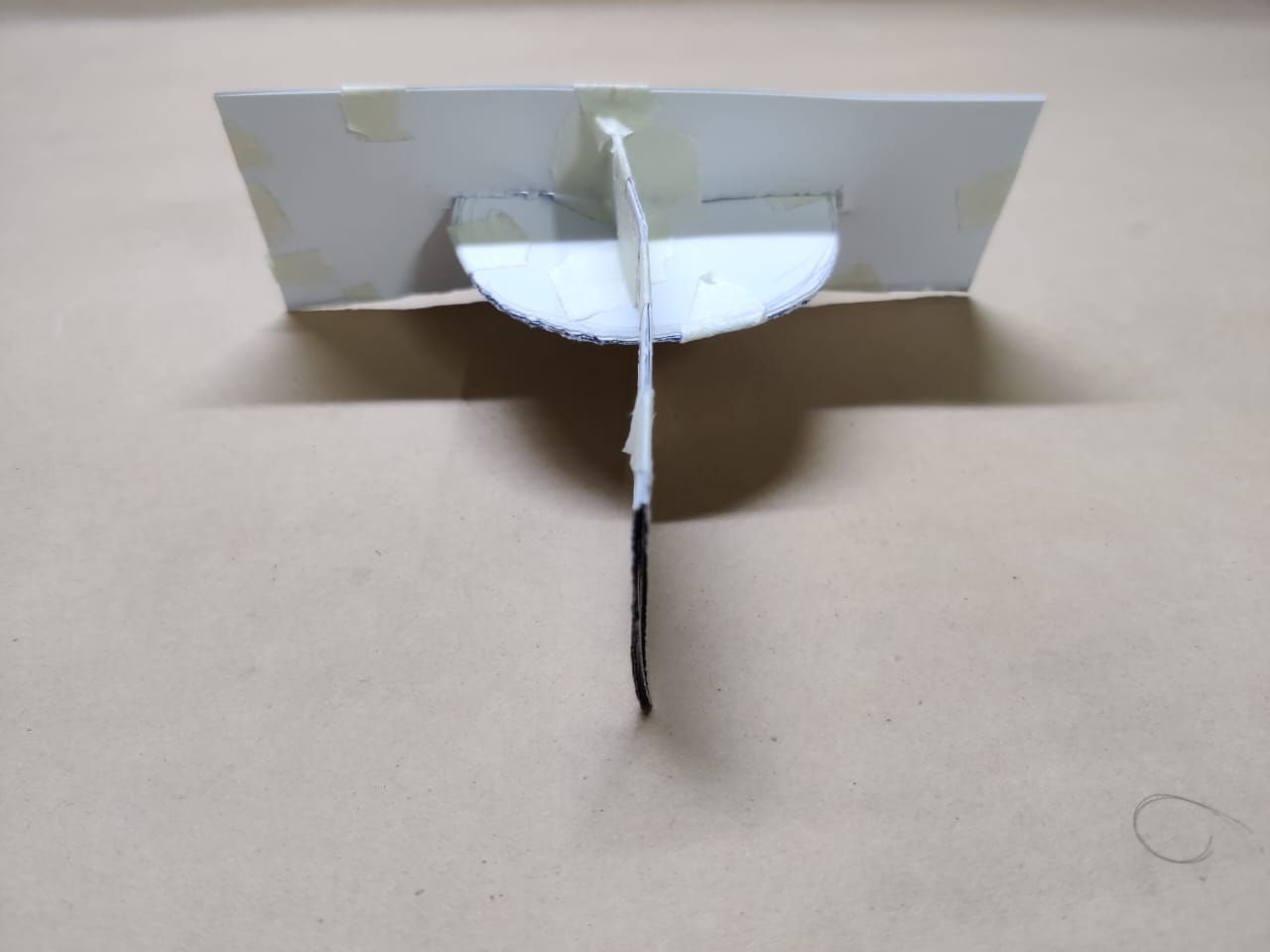
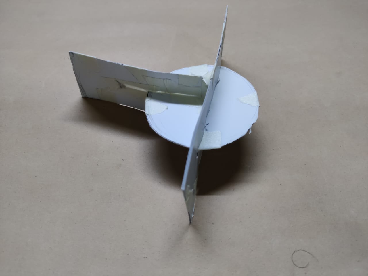
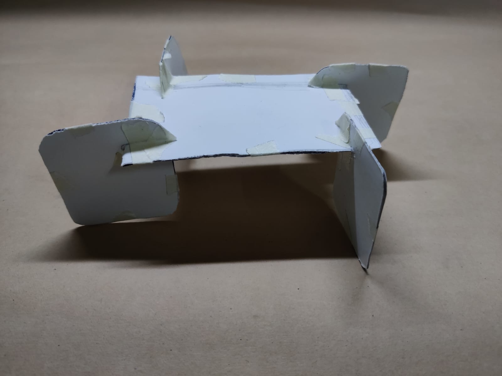
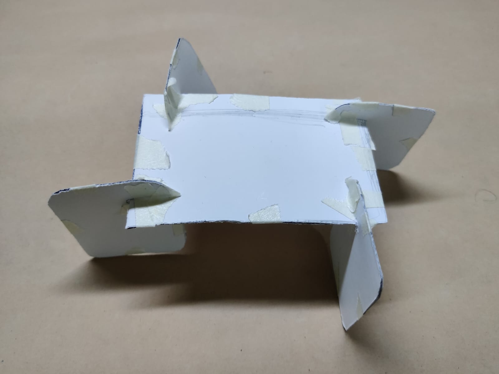
Design 6

This is also very interesting design as it's weight balance part is interesting so I wanted to try this as well.
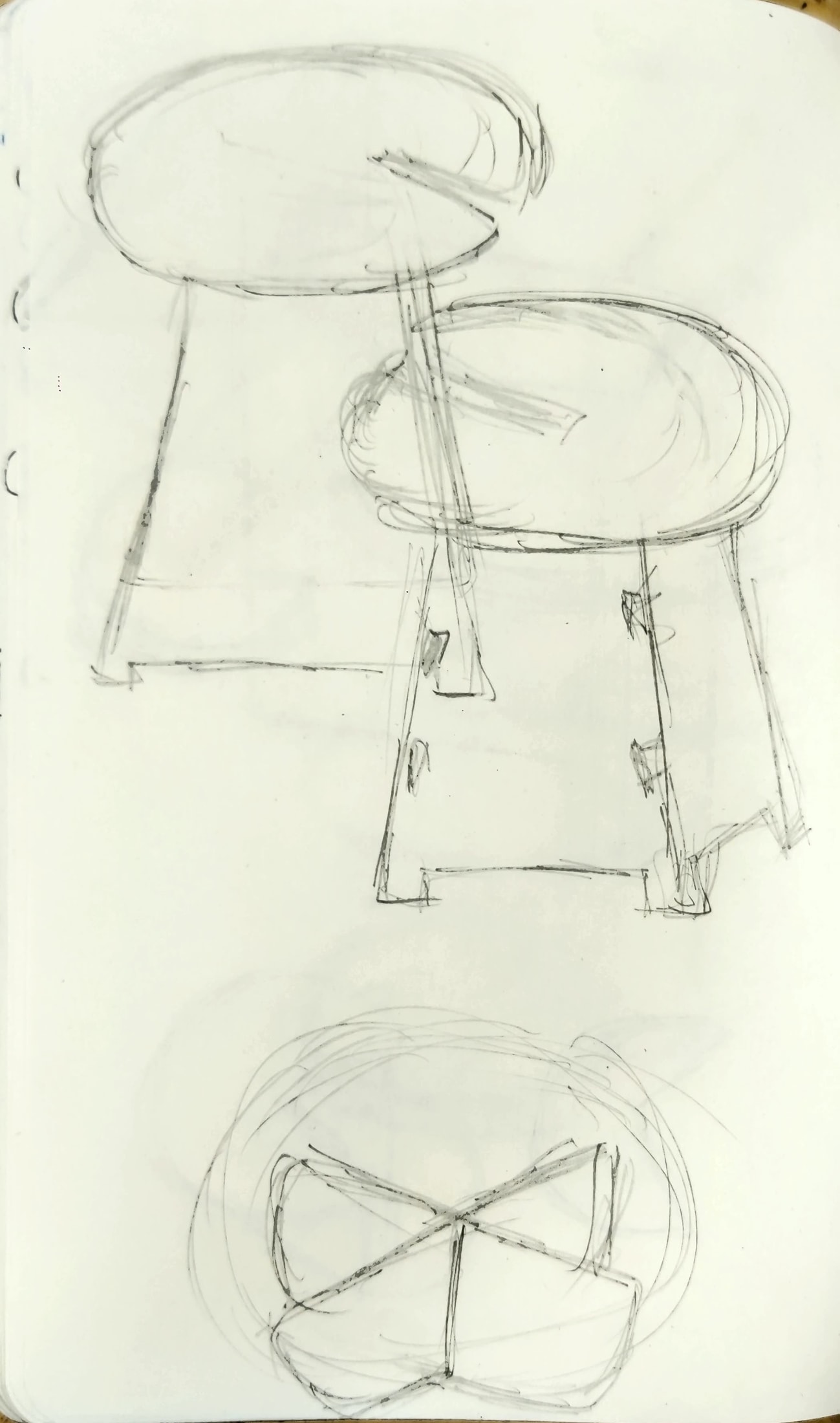
Design 7
Design 8
Step 03: Conceptualisation
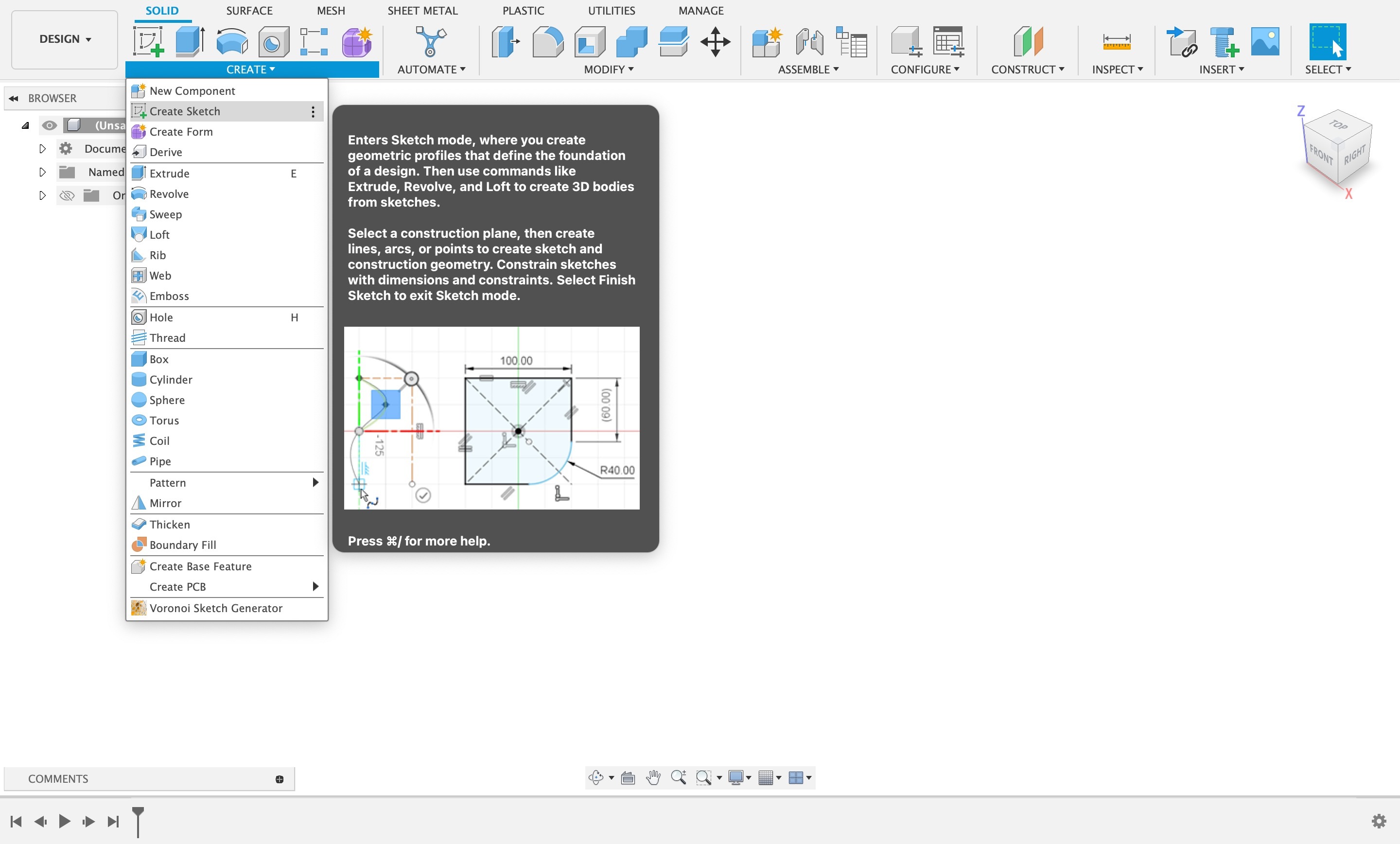
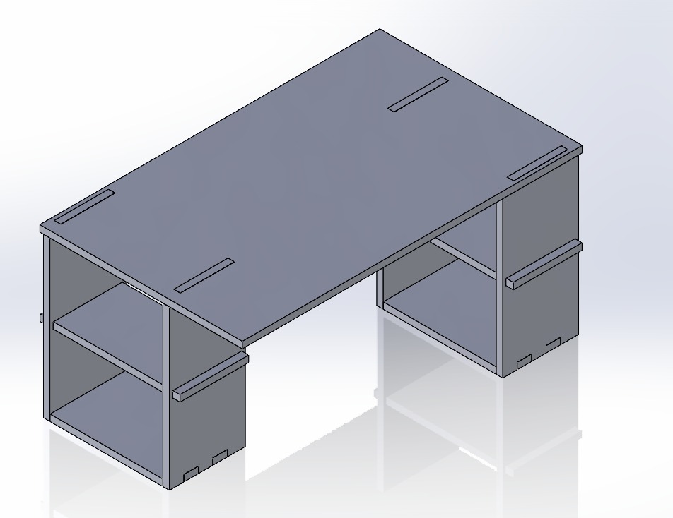
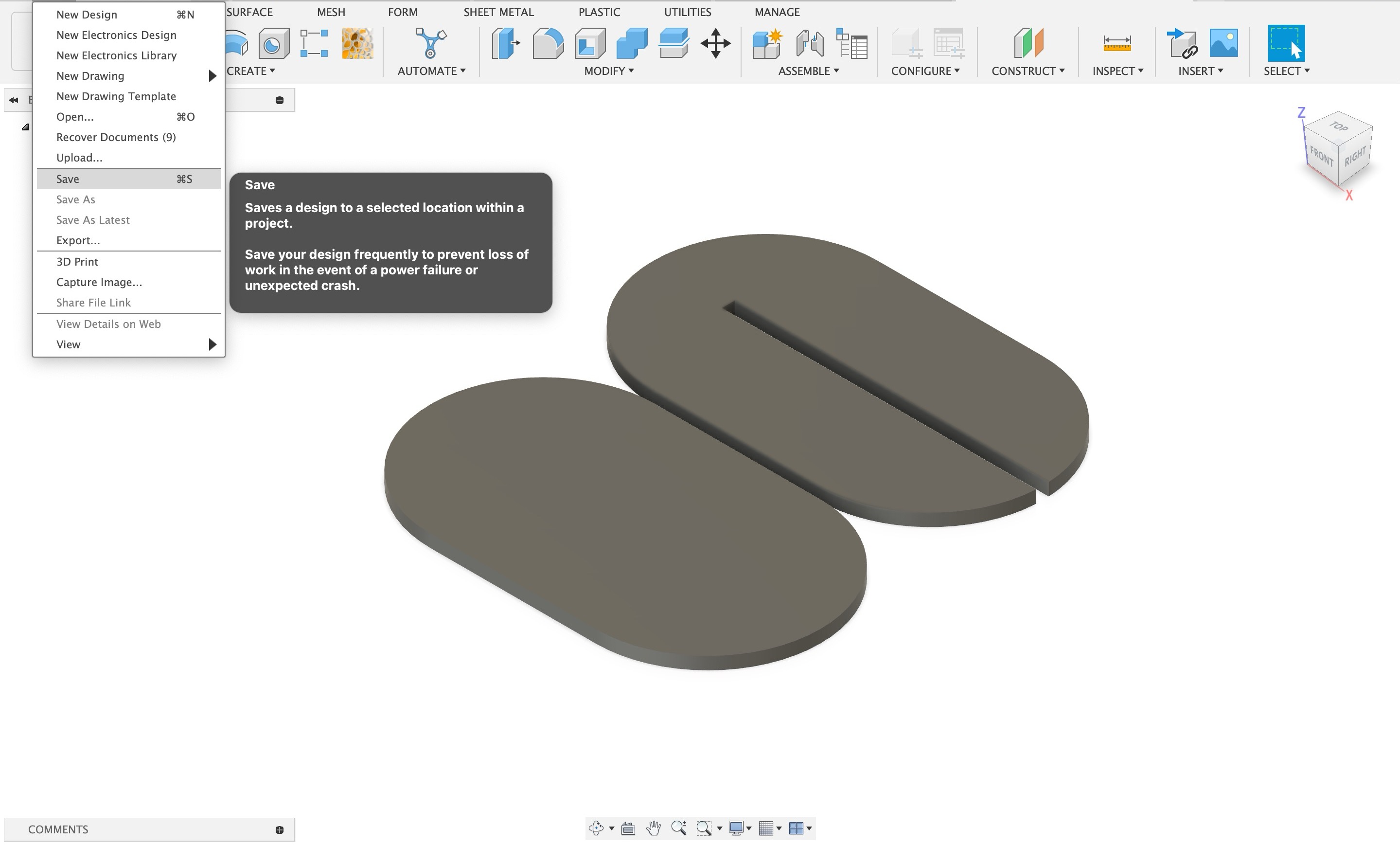
The design was designed on Autodesk Fusion 360 and the interference slots were designed based on the material thickness and the tool kerf The design is planned to be ideally assembled without glue or anything. The Autodesk Fusion 360 design looks as shown in the figures below:
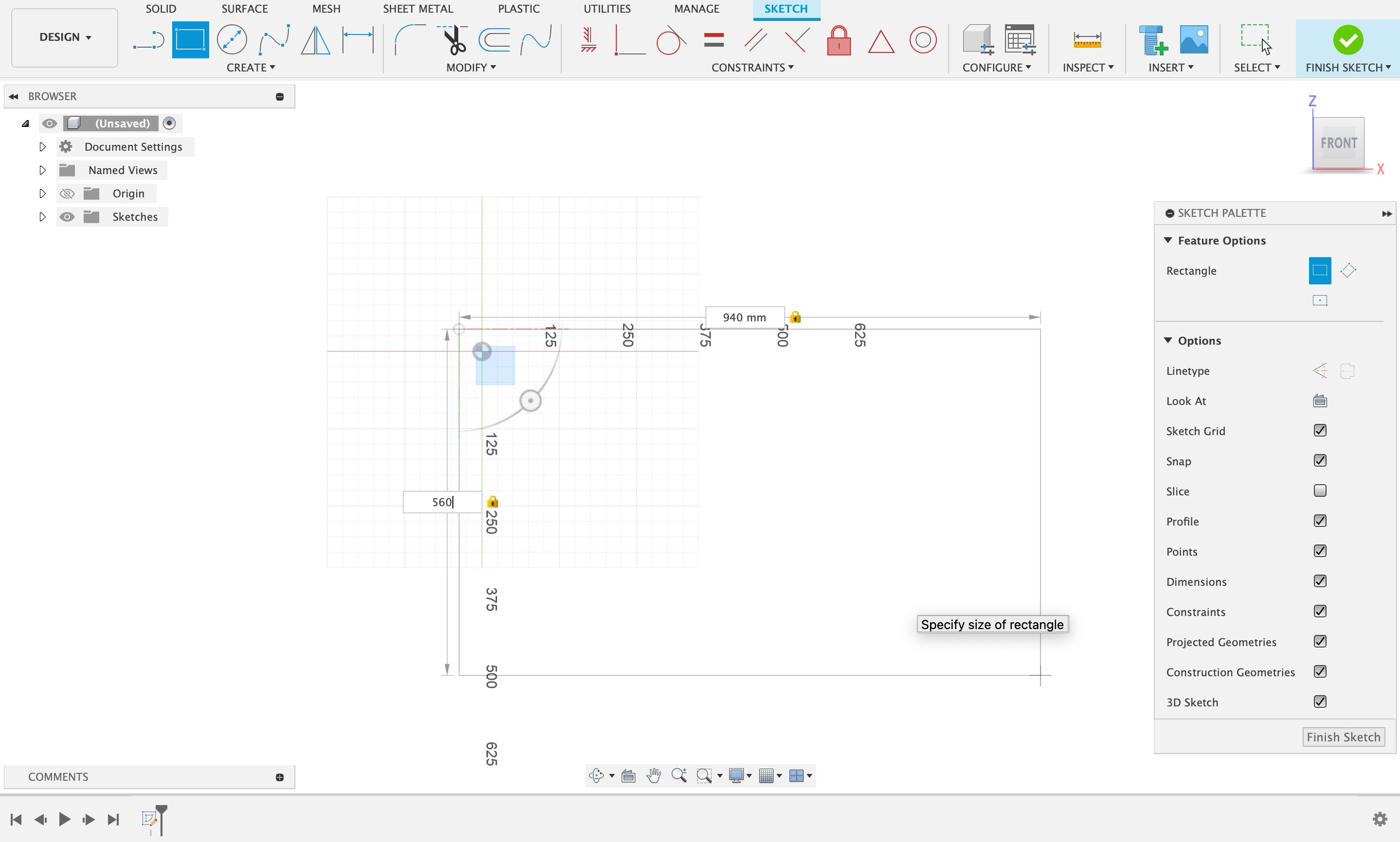
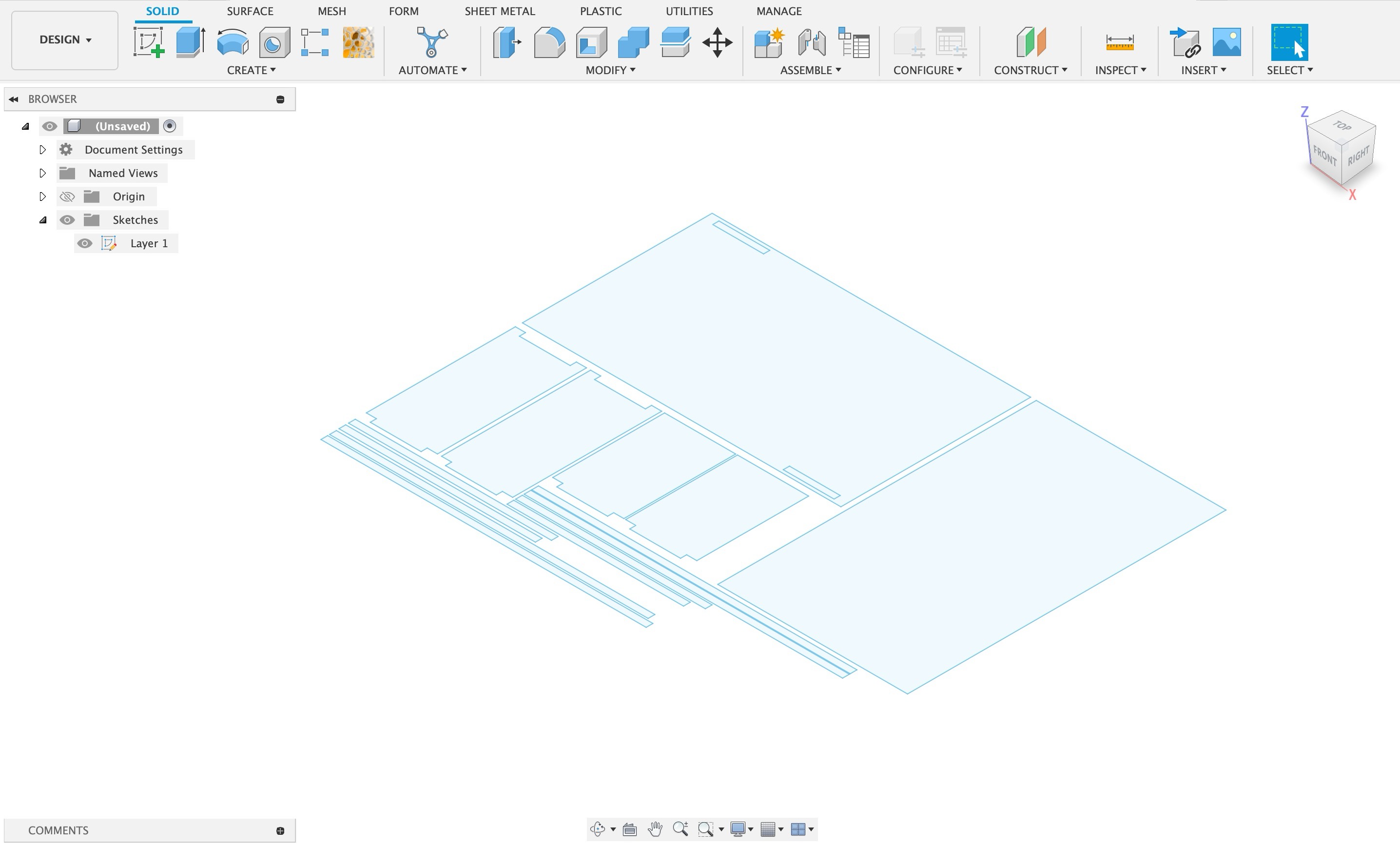
I opened fusion 360, went on sketch > create sketch and started making the sketch for 18mm table.
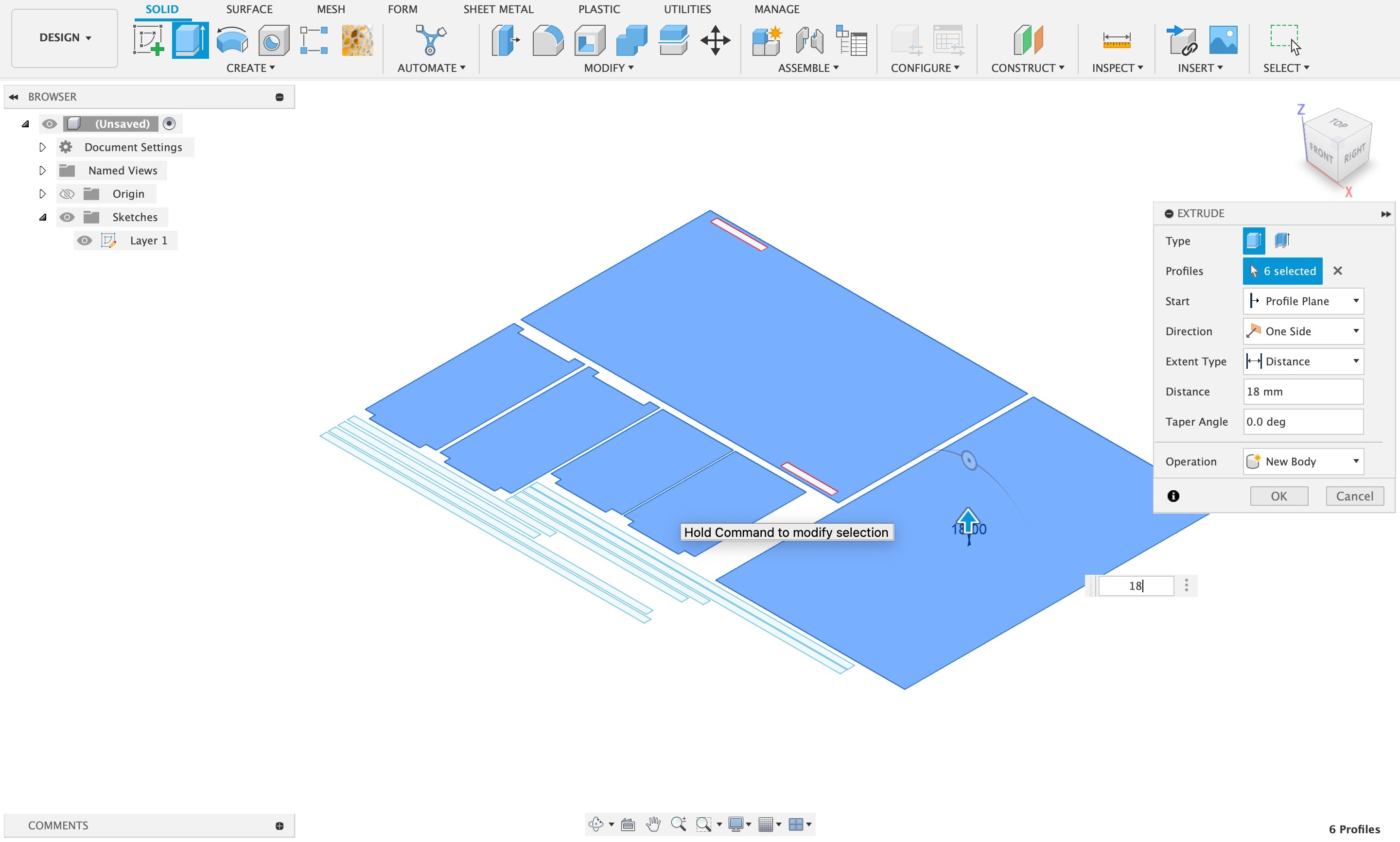
After completing the entire sketch it was now time to extrude it as i was using 18mm material I extruded it by 18mm.
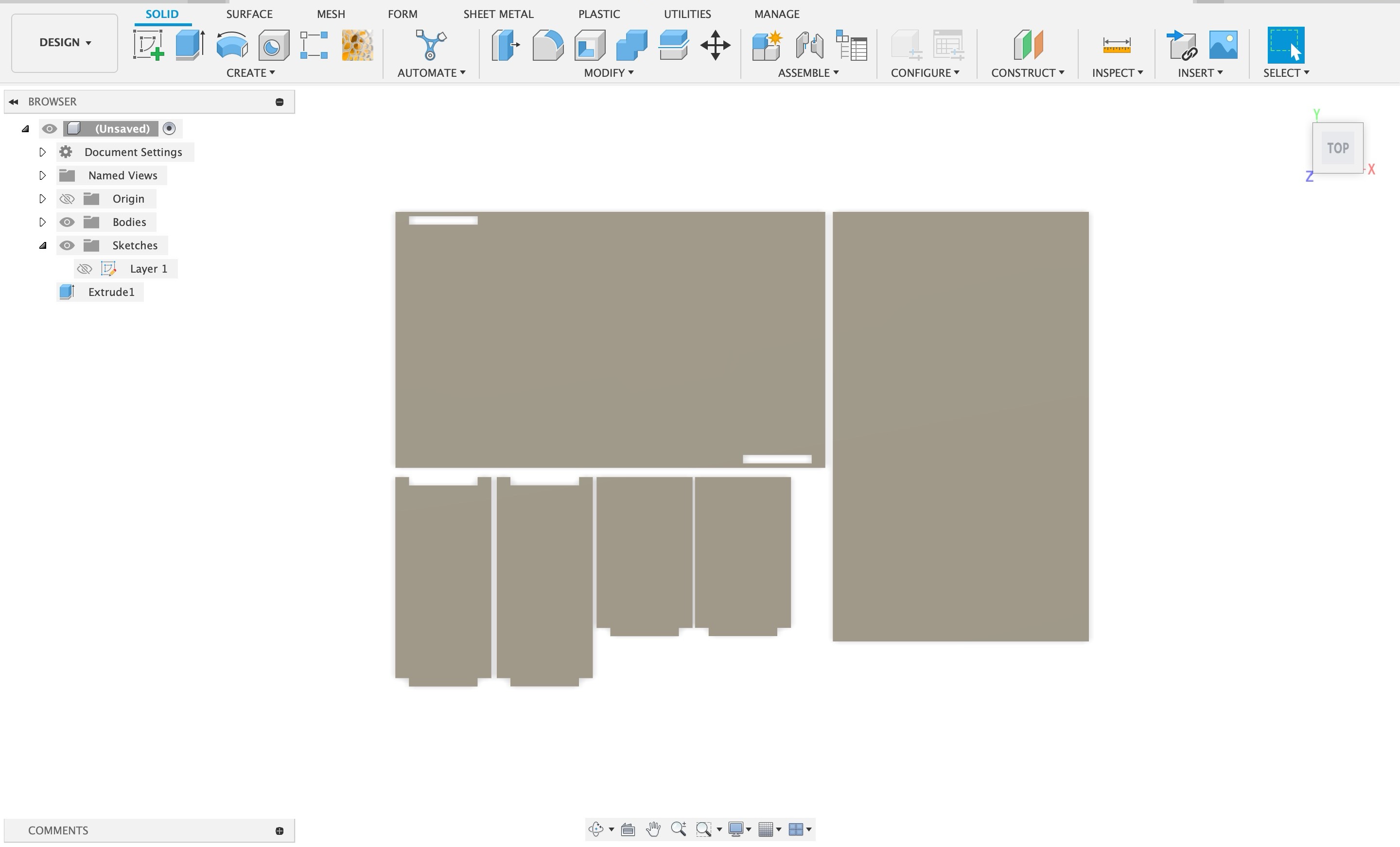
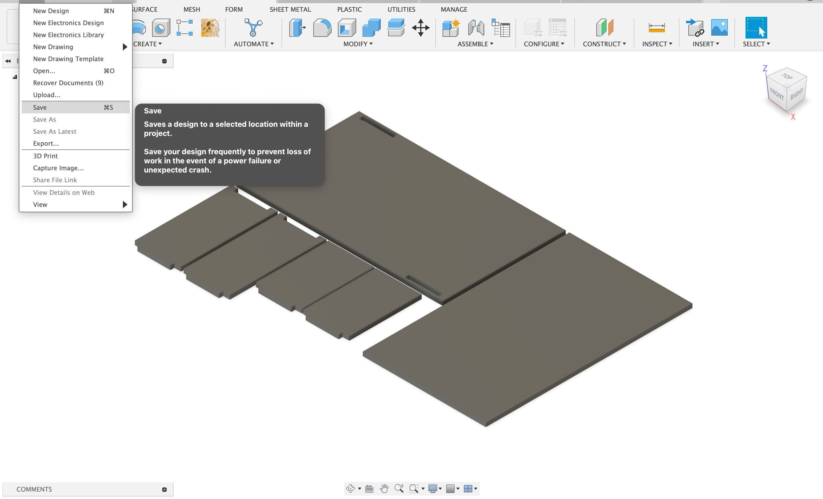
After completing the 3d cad design save the file go to file > save.
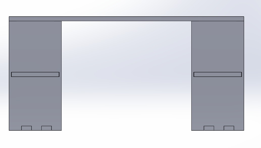
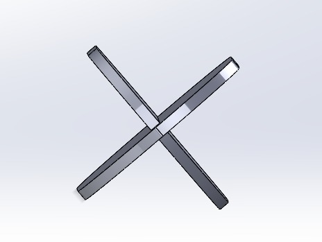
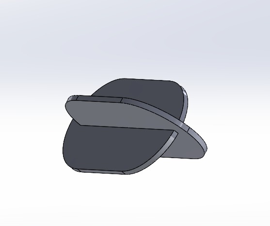
Heroshot of final renders
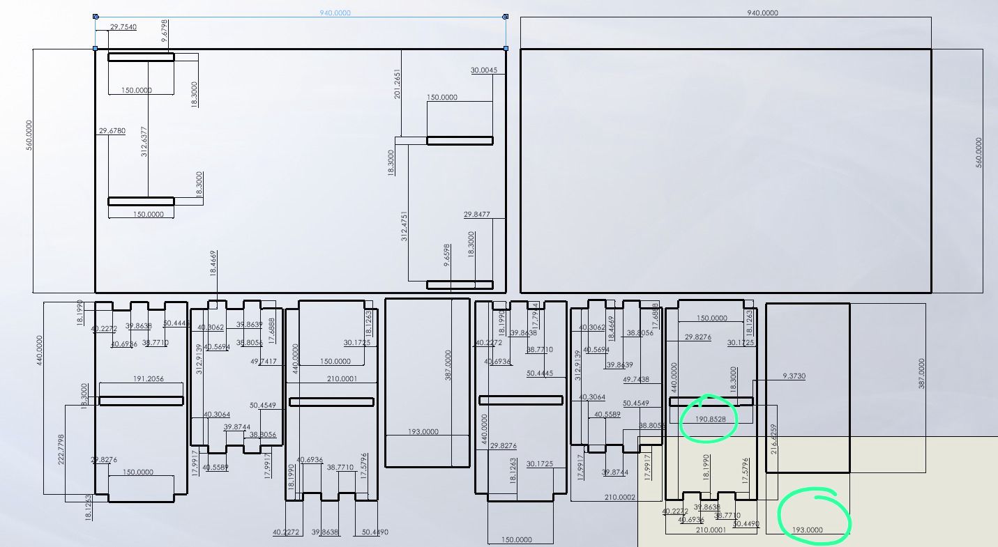
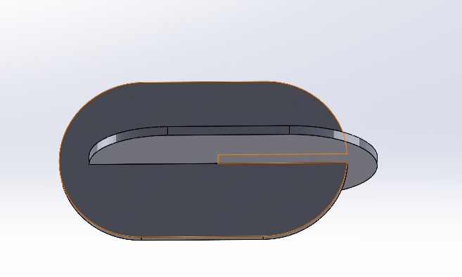
As mentioned in the group assignment on siddhart's page for slot test, to refer it click here. Initially I have kept the slot as 18mm but we did a slot test and realised that we should give a 3mm clearance as our ply was 18mm and I did the changes accordingly in my file.
To see all the measurements of my file see the image below:
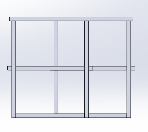
Cad Models of 2nd design
Again for this design I changed the slot distance after doing the slot test in group work as mentioned above, to know in more detail for slot test click here.
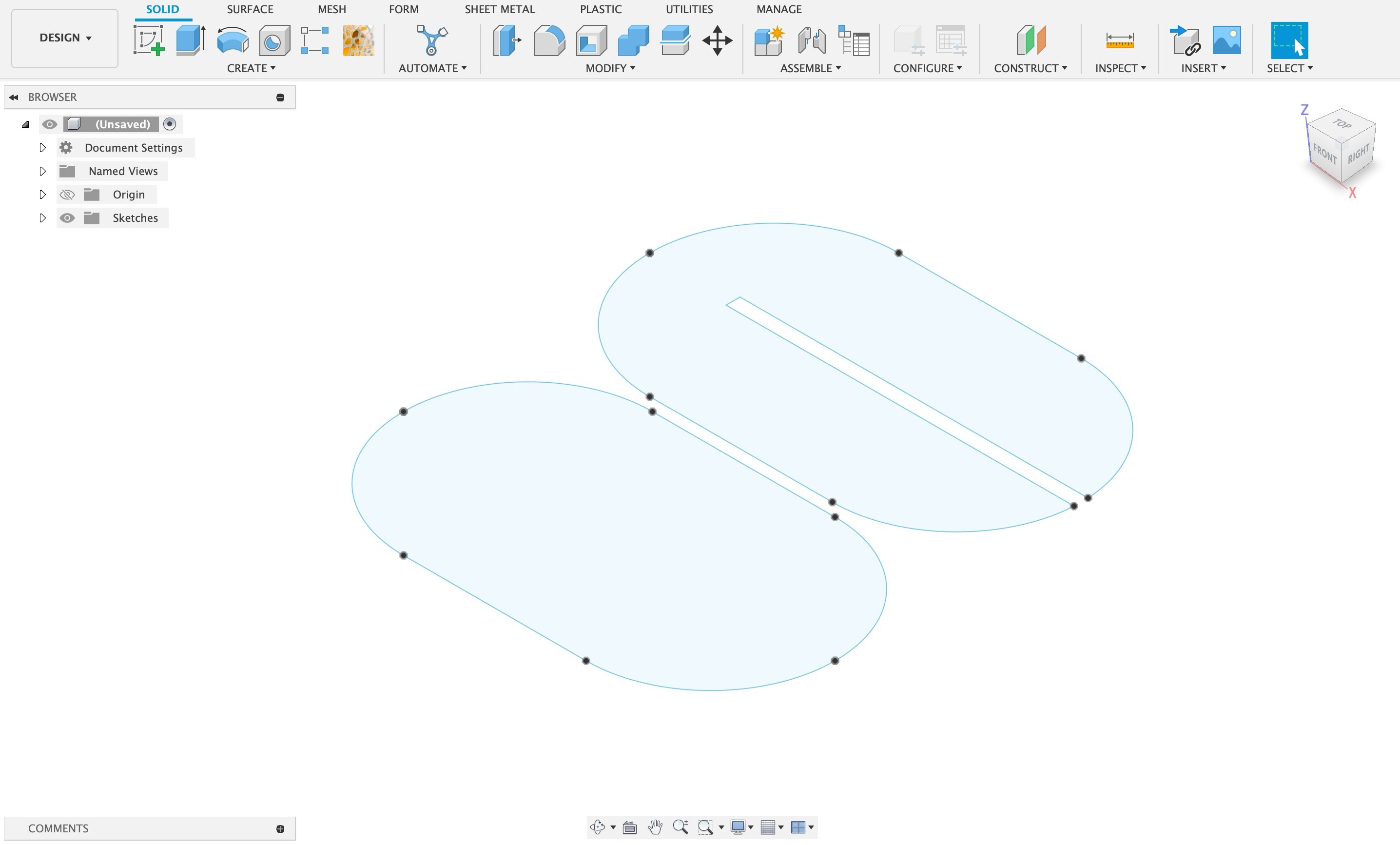
Here also I started with making sketch
Then as my material was 25mm I extruded it to 25mm
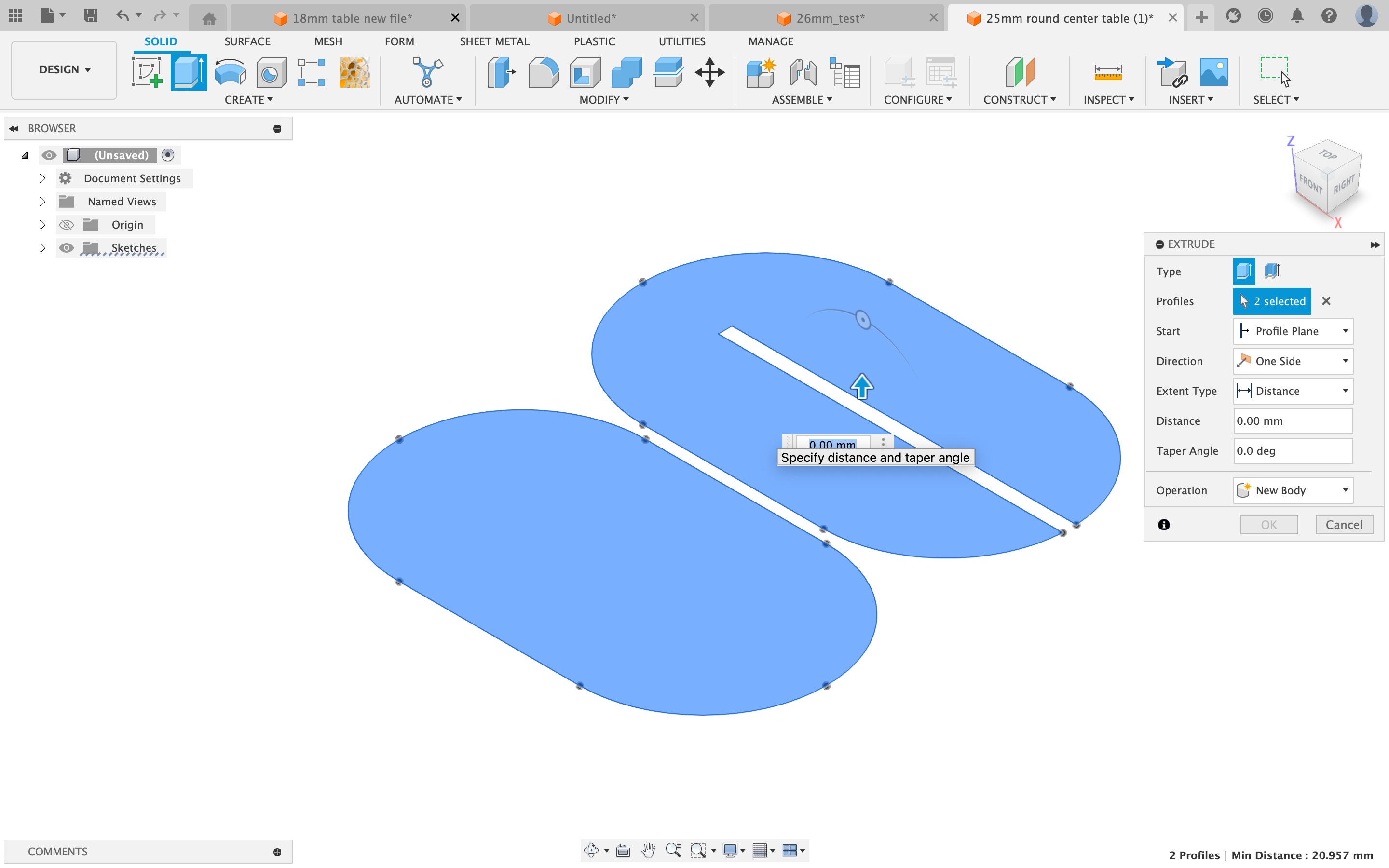
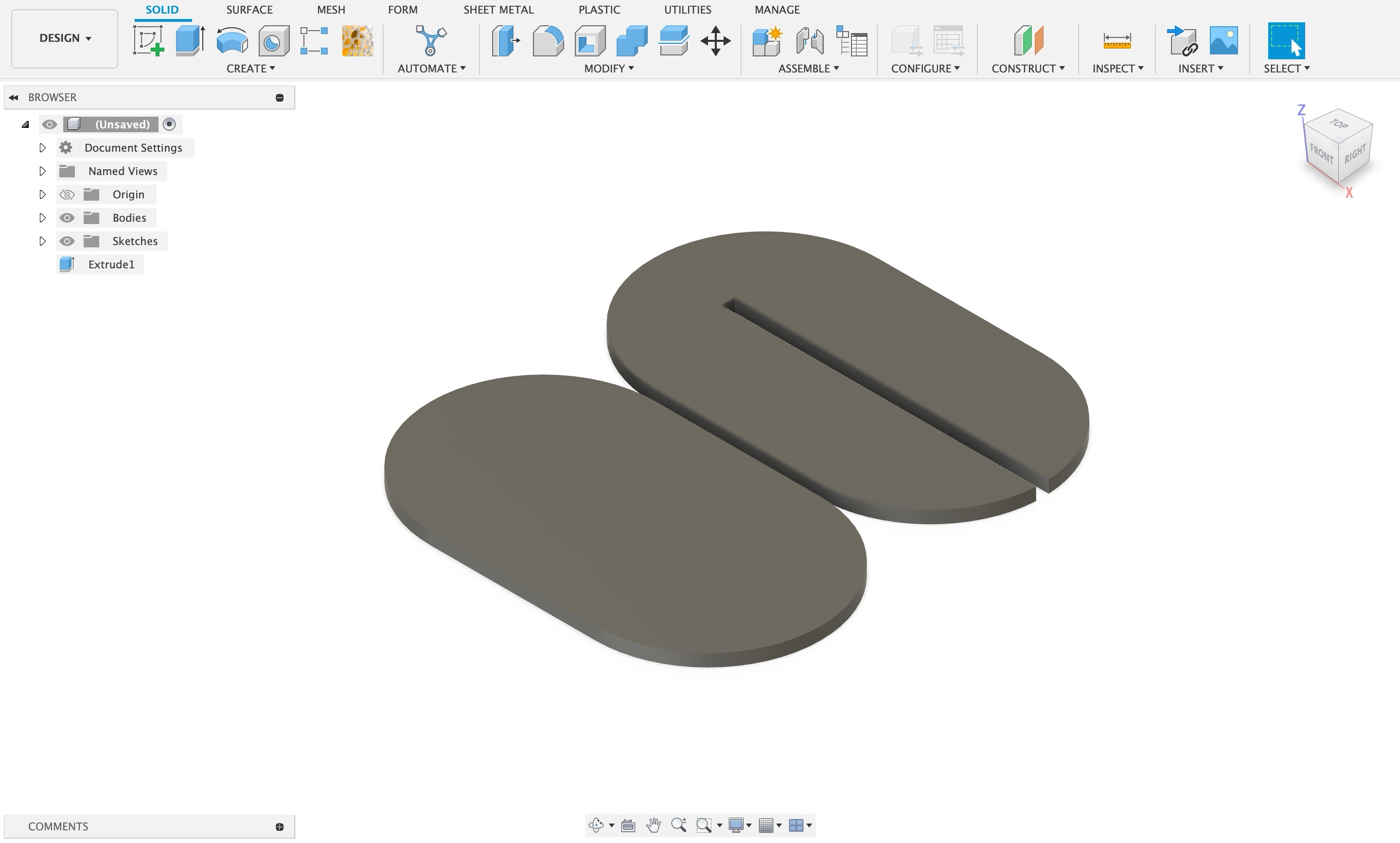
After completing the 3d cad design save the file go to file > save.
Heroshot of final renders
Step 04: Prototyping
Once the design is ready, it needs to be converted in some format which CNC machine can read. As we did not have Artcam we did it on fusion itself.The toolpath is defined in this file itself. Once the file is ready, its time to go to the machine! The toolpath is designed on Fusion 360 software.
Exploring the CNC router
The CNC router at RIIDL is quite old, but it still does a good job at cutting things accurately.
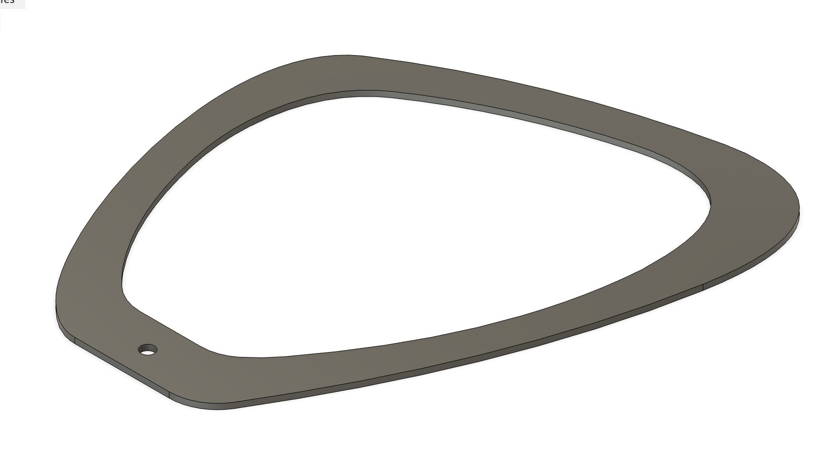
We just wanted to try the machine and know everything about the machine, so for timming we have used my previous college assignments file, I had made a lampshade this is one part of the lamp.

In detail explanation of how did we tested the old file, making toolpath and new test file is uploaded on our group assignment Siddhart's Page
What went wrong during test cut?
The outer ring seemed fine during the simulation, but during the air trial, the router's movement was extremely stuttered and jittery. We couldn't figure out why this was happening, and our instructor advised against making the cut to avoid damaging the tool and the plywood.
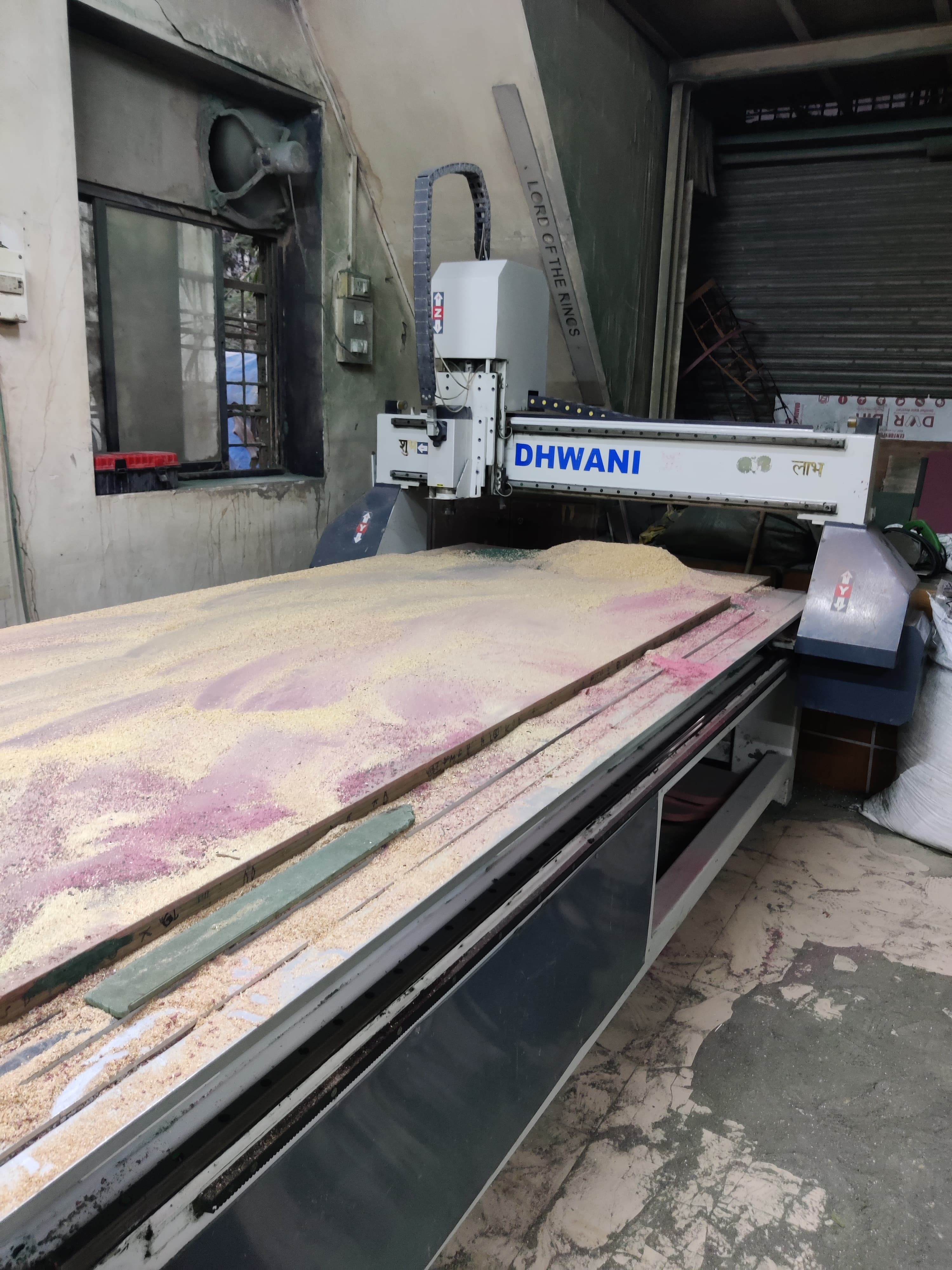
So, we decided to pause the cutting for that day and the next week we sourced the machine from outside.
The entire documentation of group work is uploaded on siddhart's page as linked above.
Material
On 25 mm material I cut this design
On 18mm material I cut this design.
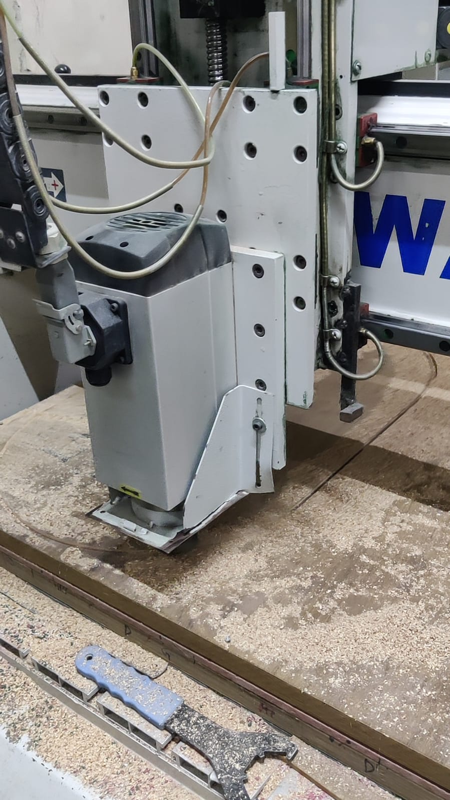
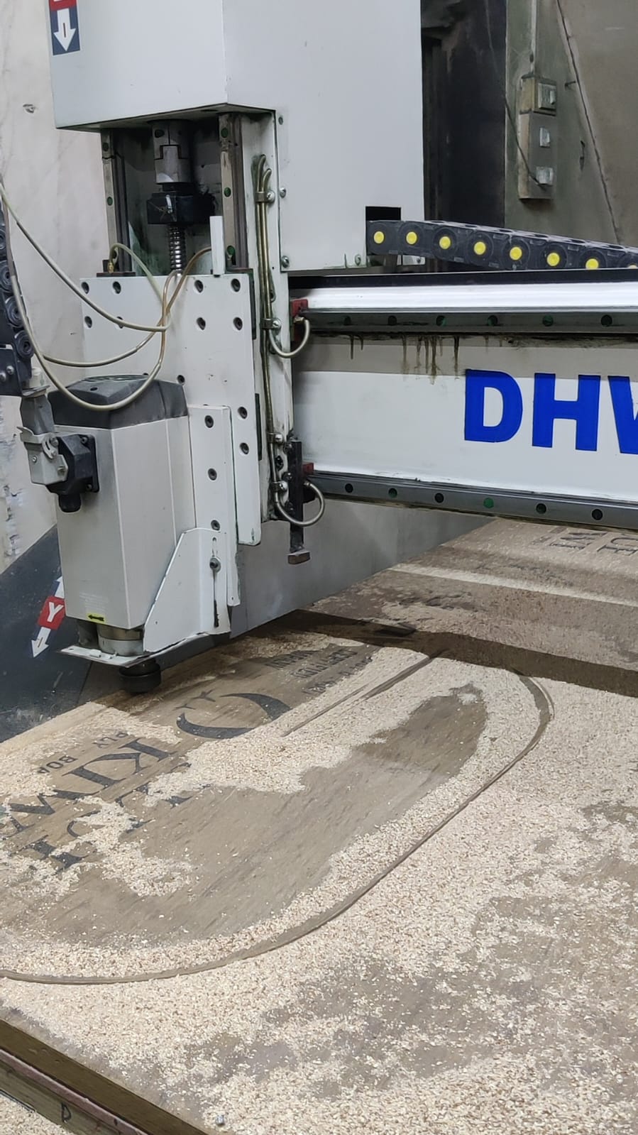
This is how the machine looks.
Toolpath
We made toolpath on artcam and gave it to the vendor, below are the detailed steps and video of how did we generated the toolpath.
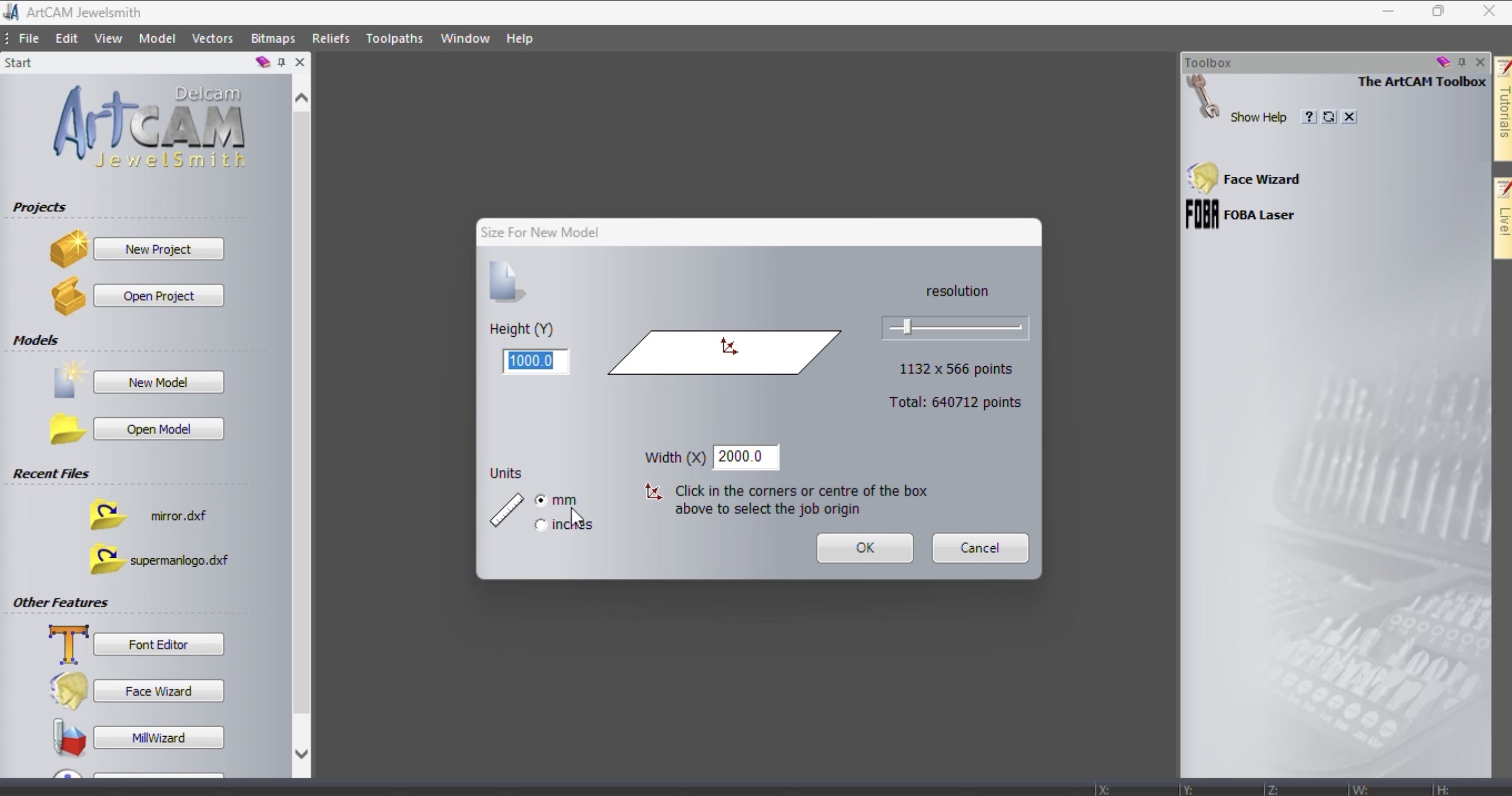
As soon as you open the software it asks you for the size of new model, write the height and width of the new model and press ok.
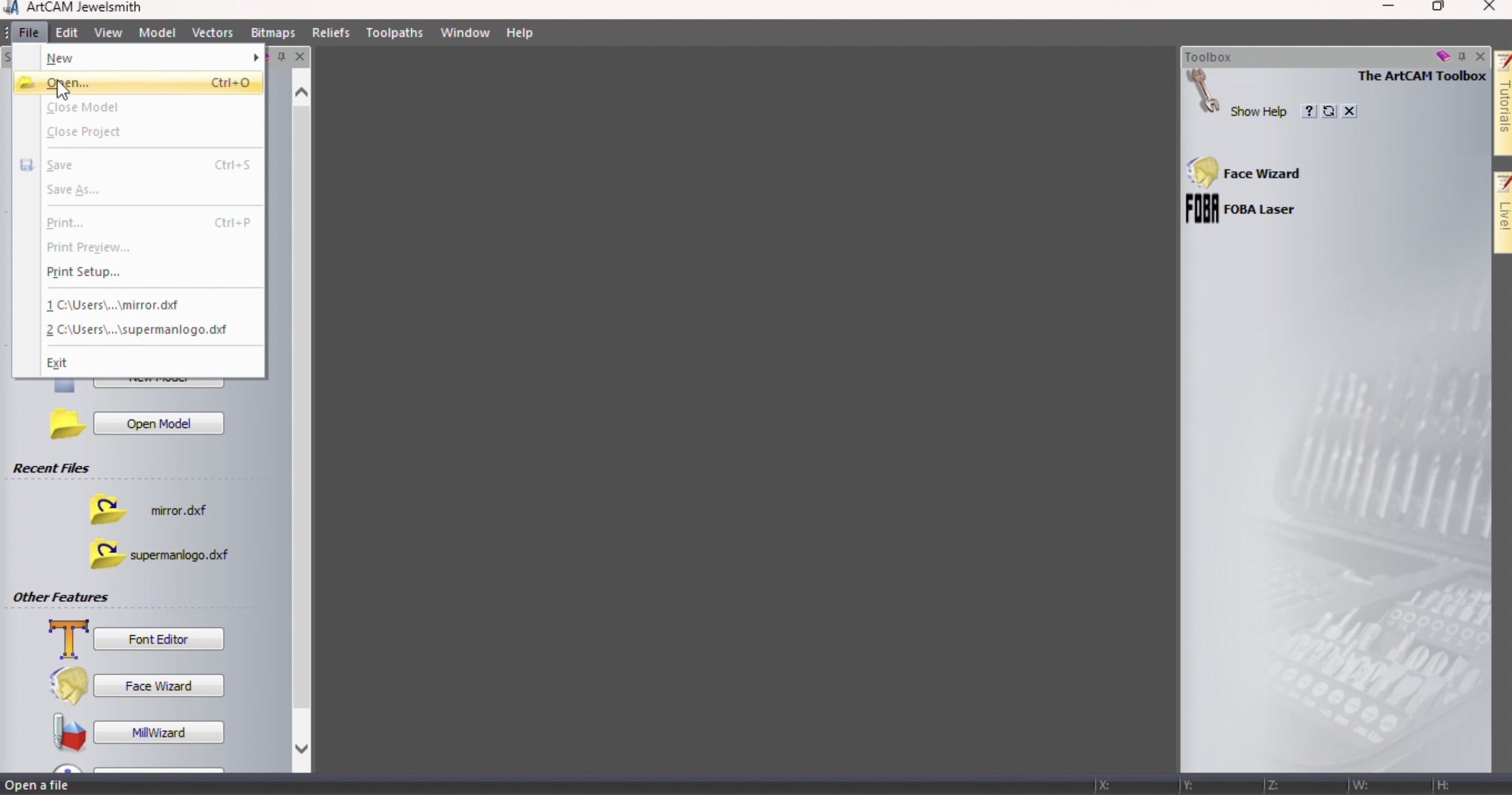
Go to file > open > open your file
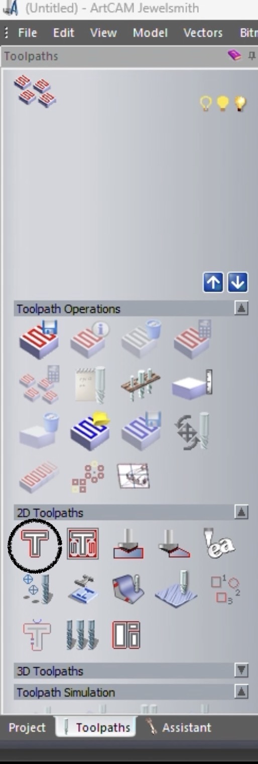
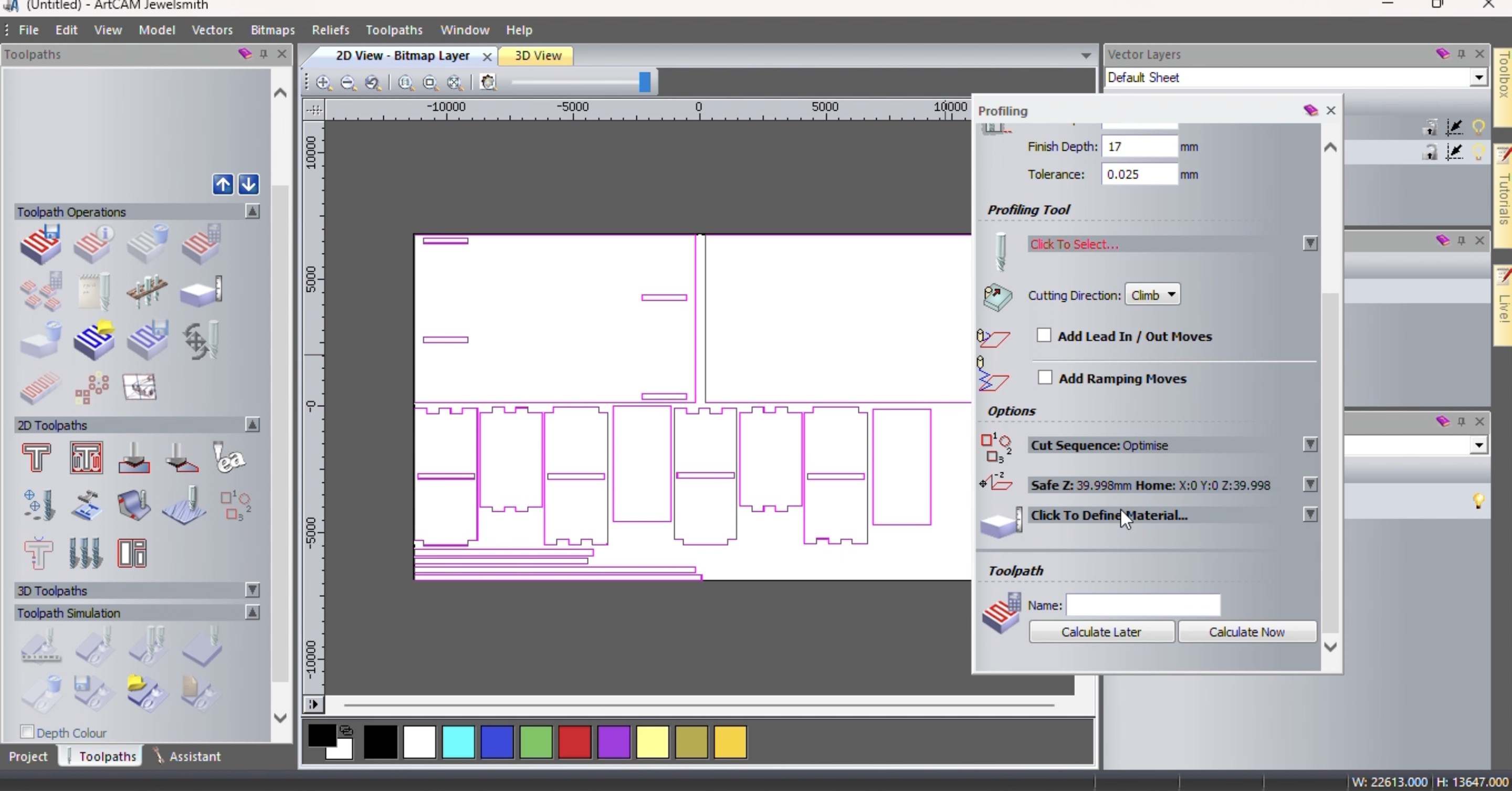
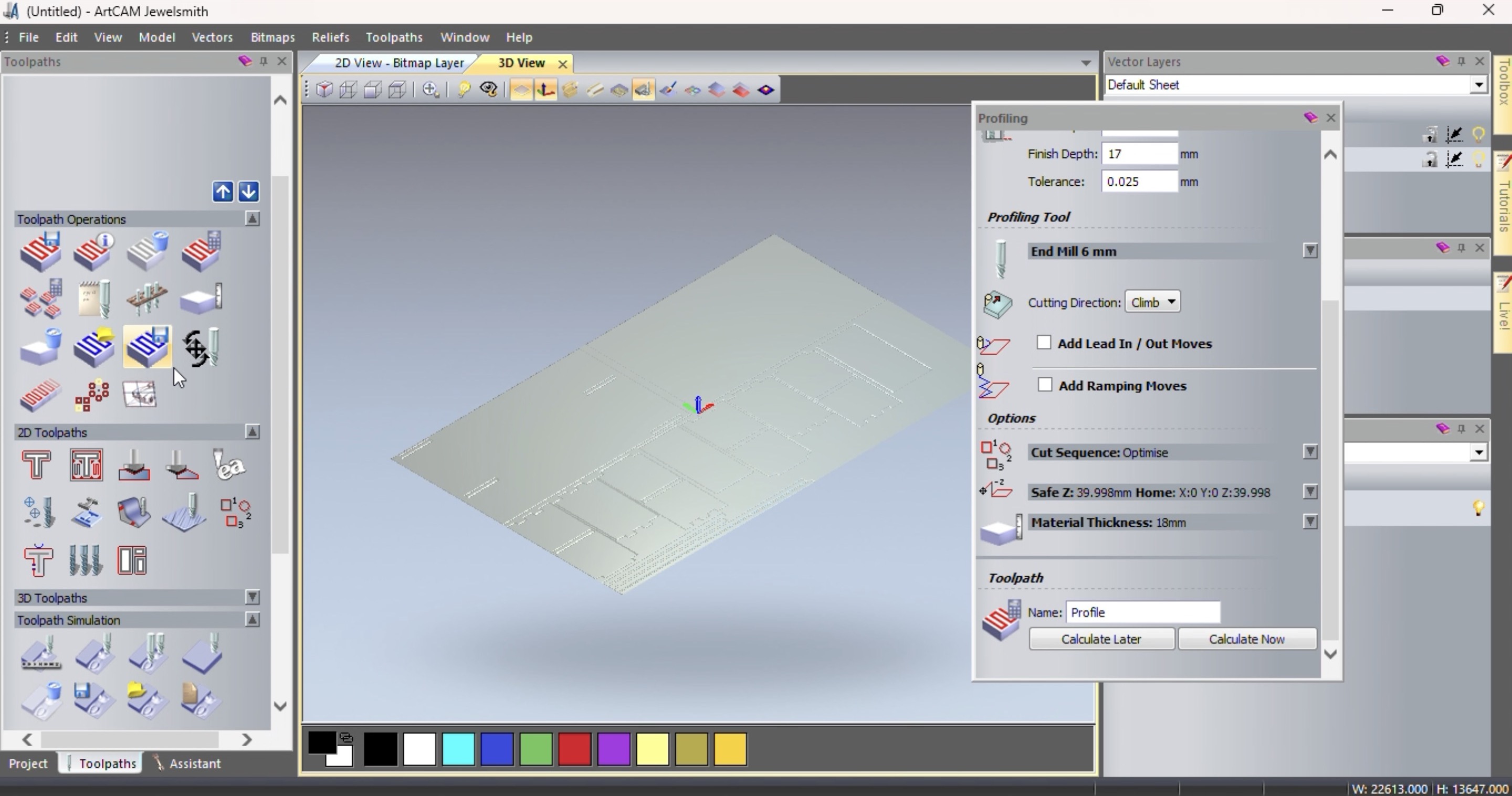
On the left hand side you can see 2d toolpath there click on toolpath as marked in the image below, if your file is a 3d file then select 3d toolpath.
Then a profilling window will open.
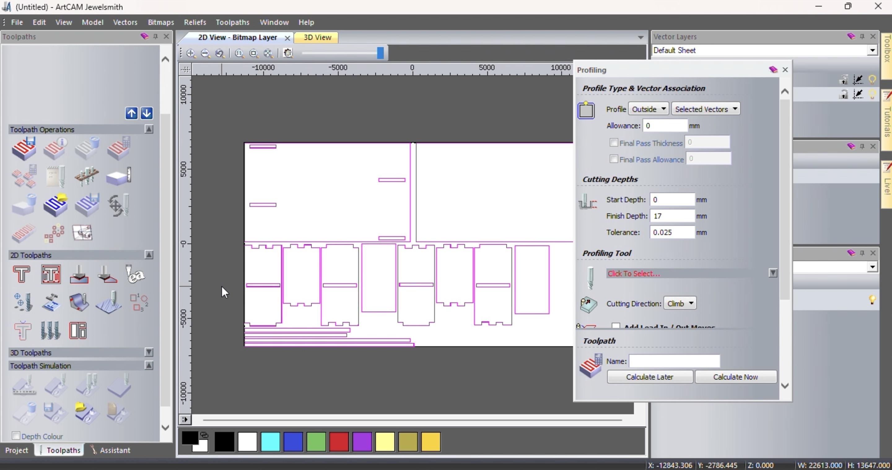
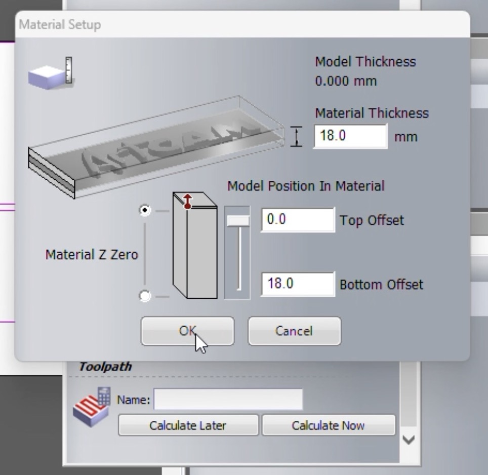
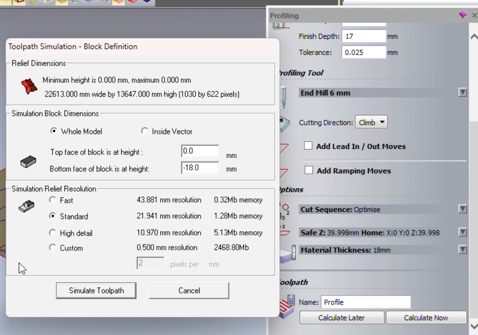
Scroll the profilling tab below and there is a option of define materials click that.
Define materials thickness and press ok.
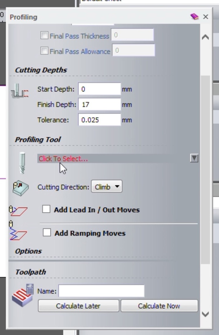
In the profilling tab now select profilling tool
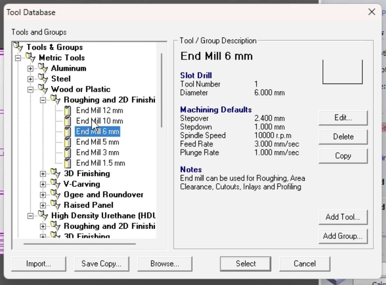
Now we need to select the tool depending on which tool we have and on what material are we using that tool, we had 6mm end mill so I selected that and we were cutting on mdf so I selected wood or plastic section in that roughness and finishing tool I selected 6mm end mill.
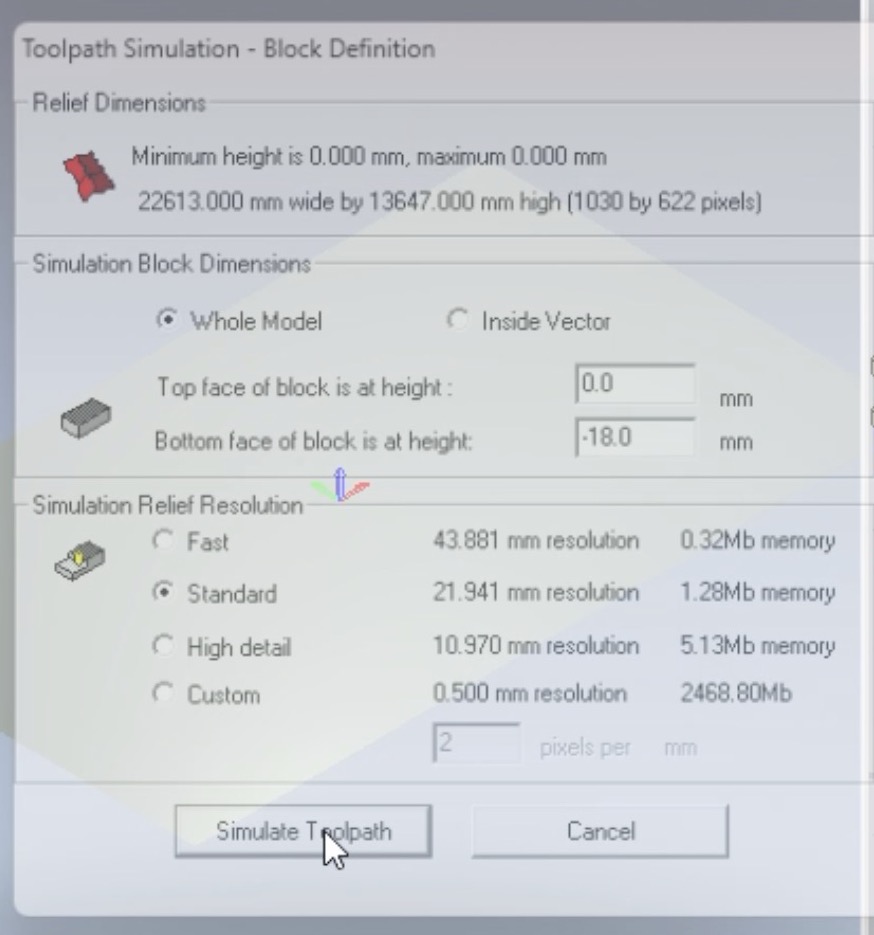
In the profilling menu click on calculate now and a new window known as toolpath simulation will open in that click on simulate tool path.
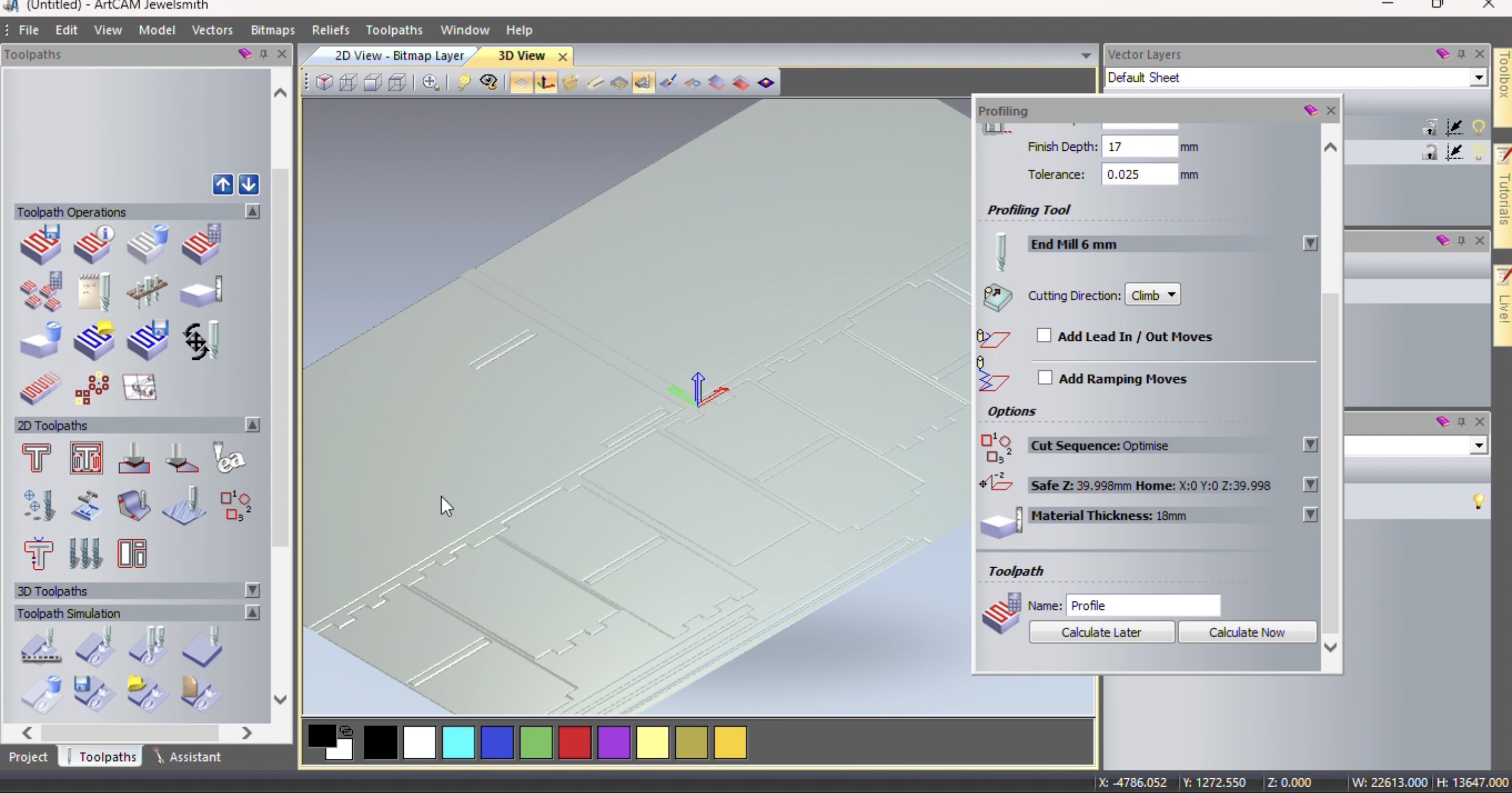
Then the toolpath starts simulating you can see the results here
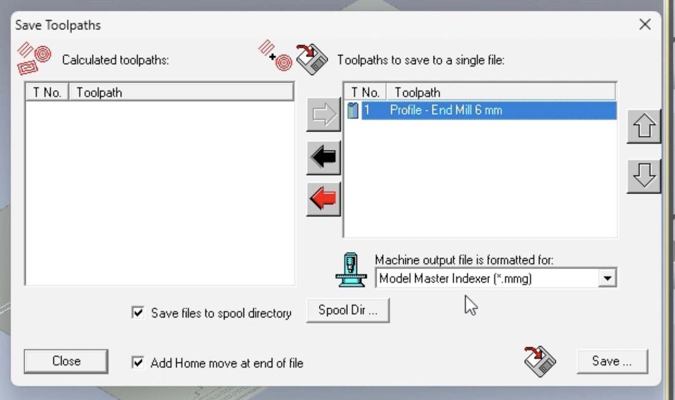
Now the toolpath is created, go on the above menu in toolpath section there select save toolpath
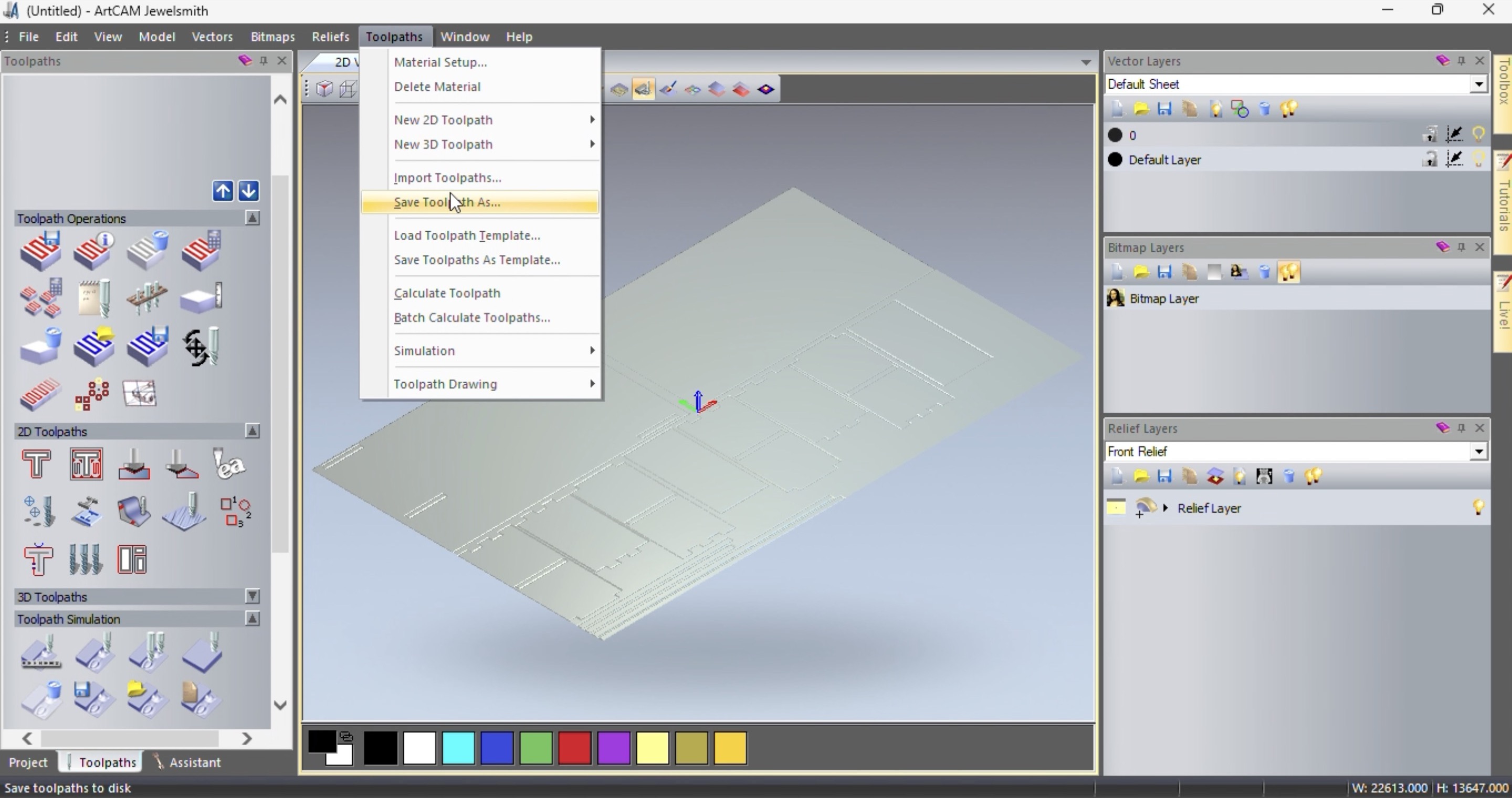
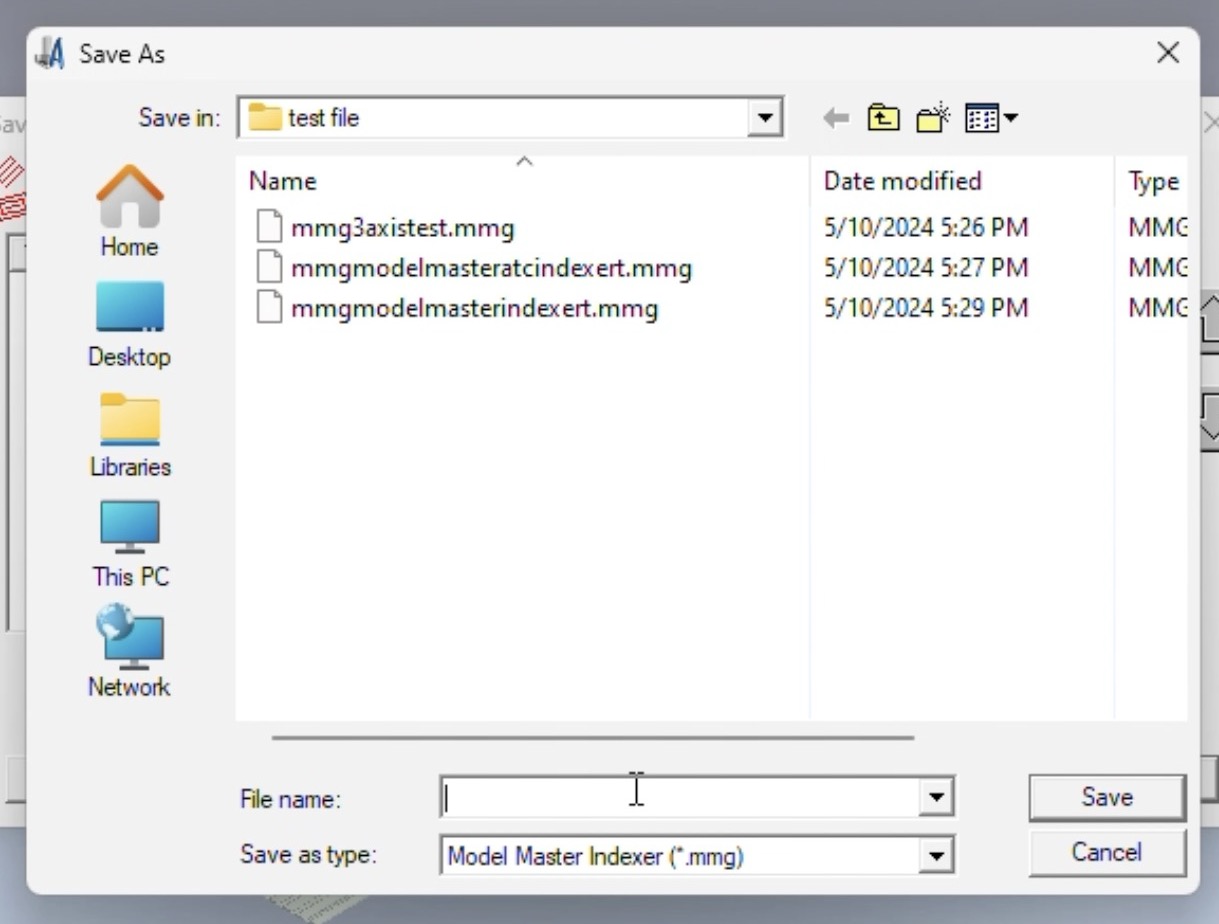
Our machine takes .mmg format so I saved it in .mmg format.
After that click on save and save it on your computer.
Here we made toolpath on artcam and we required dxf format file for the same. Below is the detailed video of how did we made toolpath on artcam.
Machining Process
The detailed machining process is explained in group work on Siddhart's Page.
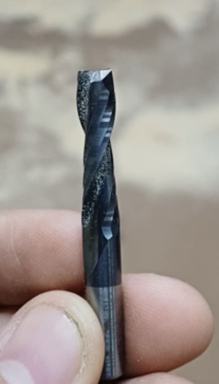
Tool
The tool we used was 6mm endmill for 18mm material and 8mm endmill for 25mm material.
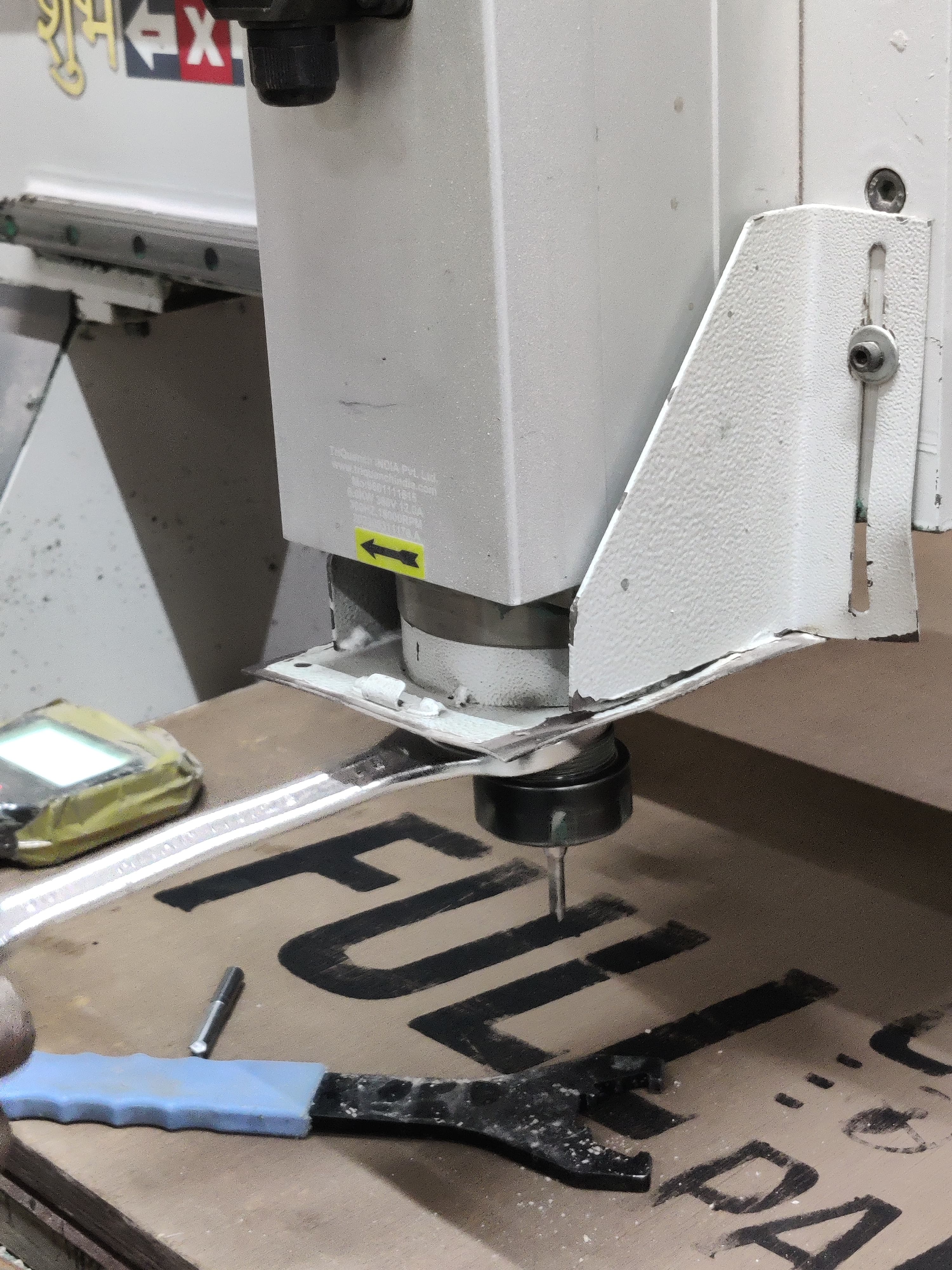
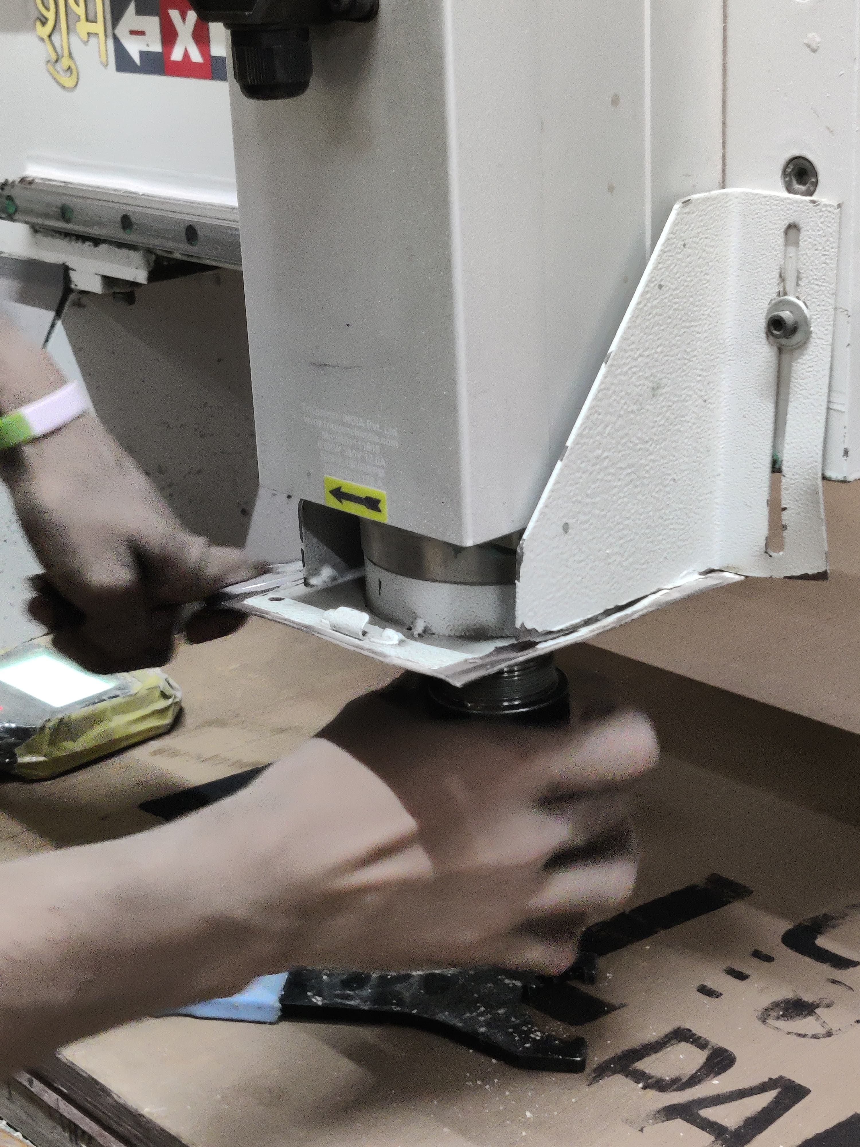
Changing tool
To insert or remove the tool, use two spanners to turn the nuts in opposite directions.
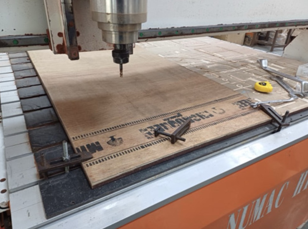
Clamp
Once the tool is inserted use clamps to clamp the material on the bed.
We used clamps that fit into the groove on the bed on one side, and then tightened the nut and bolt to secure it in place.
Machining
After creating the toolpath and converting it into an mmg file, copy the mmg file onto a USB drive and transfer it to the CNC machine.
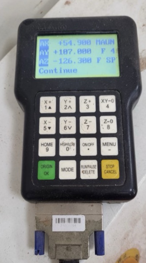
This is the machine's controller. Insert the USB drive and select the desired file. Then, input the Speed and Feed parameters, and set the origin.
The XY origin should be aligned with the corner of the bed, matching the point specified in the Toolpath file.
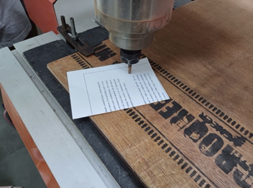
To set the Z origin, we use the paper method. Slowly lower the router until the tool's tip touches the stock. Then, raise it slightly using the controller and insert a thin piece of paper (printer paper works) underneath. Slide the paper along the stock surface.
Adjust the Z height until there's just enough friction between the tool and the paper. The paper should slide with some resistance, allowing you to feel the tool's tip dragging on the paper.
Test slots
We did a test slots on 18mm and 25mm when the ply arrived the detail explanation is explained on siddhart's page.
Cutting Process
Press on start and the cutting begins as our tool was 6mm and material was 18mm. Each pass is 6 mm and that is why 18 mm takes 3 passes. Each pass may be 6 mm because it may not be recommended to have pass depth > tool dia..
To see the video of cutting, click below:
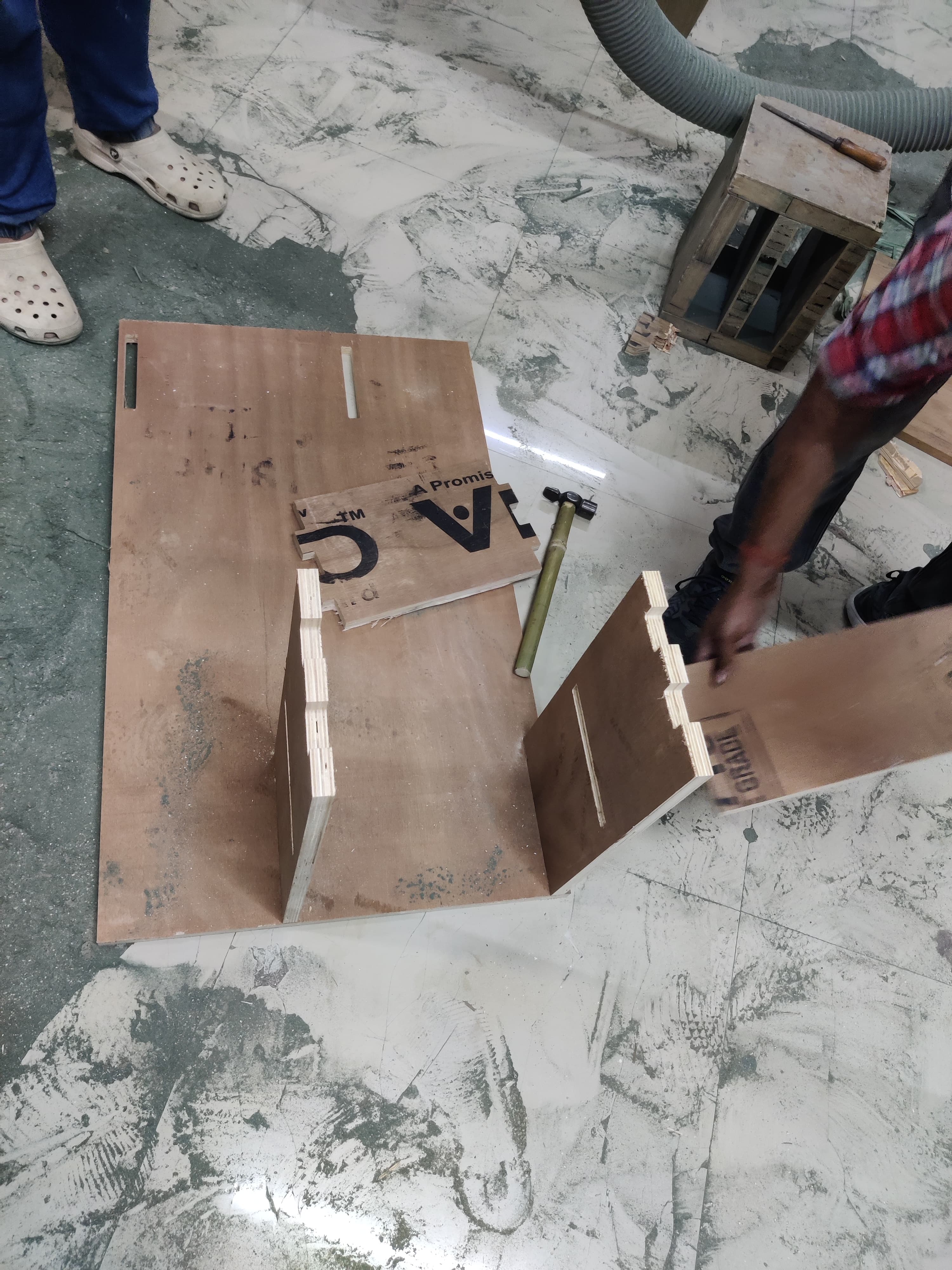
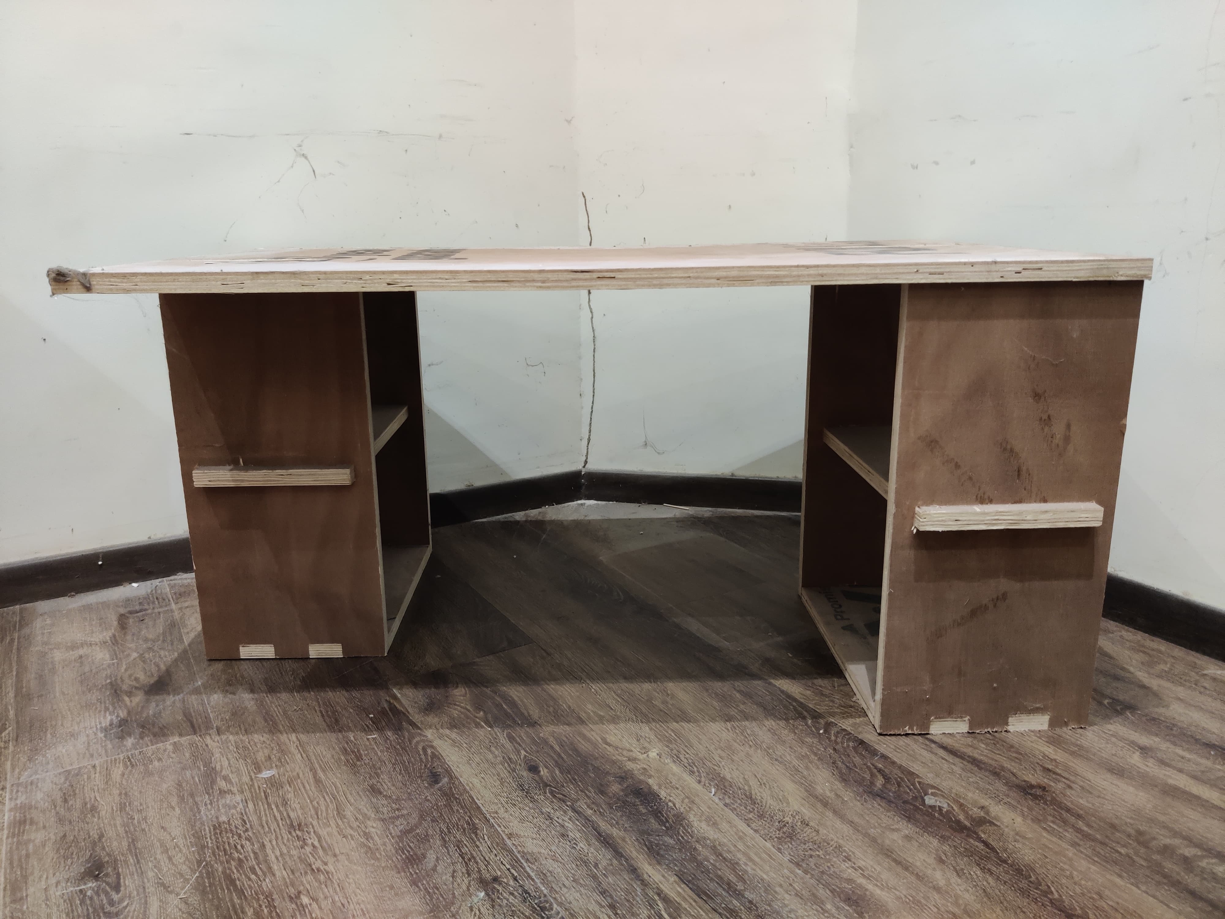
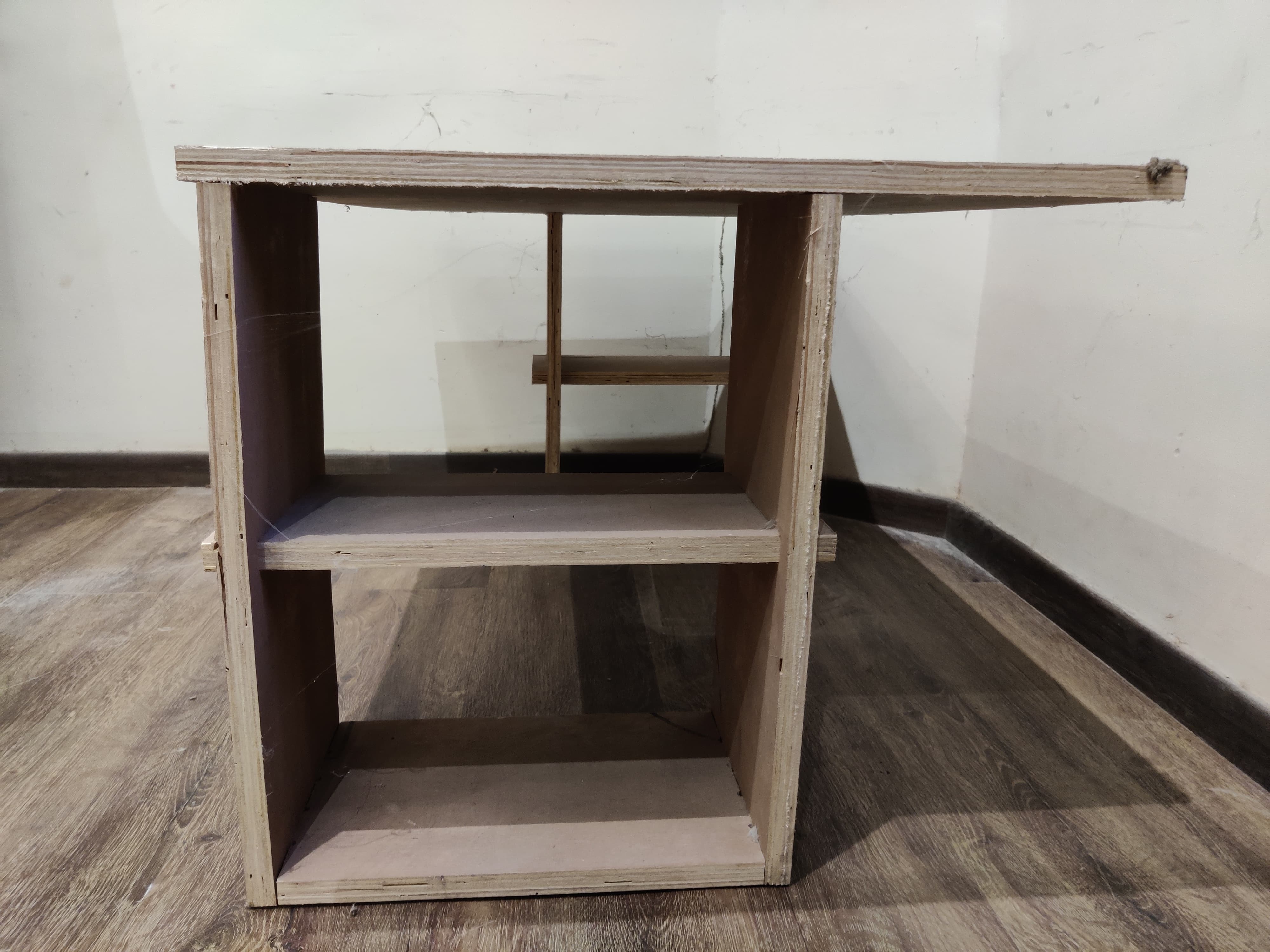
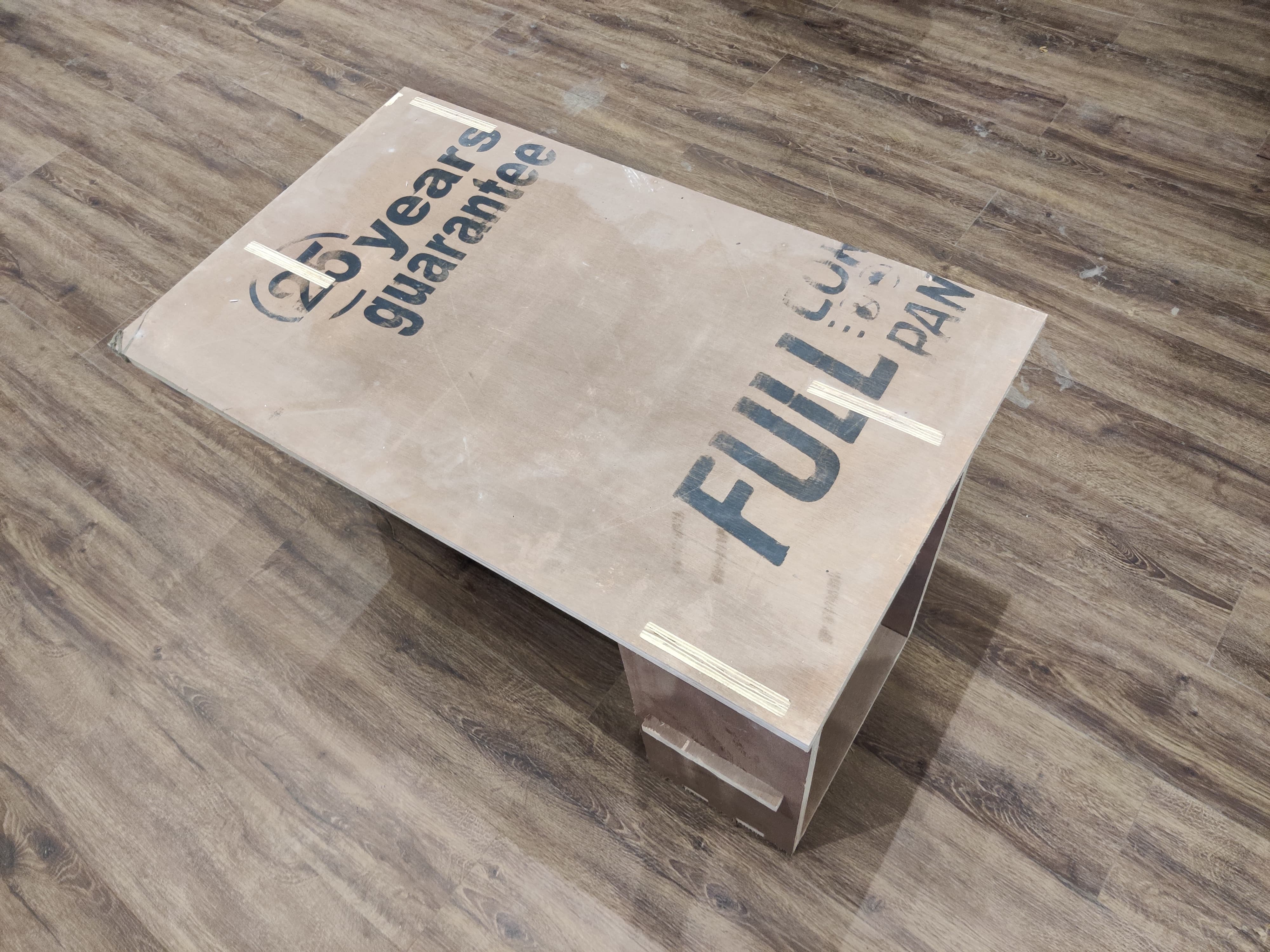
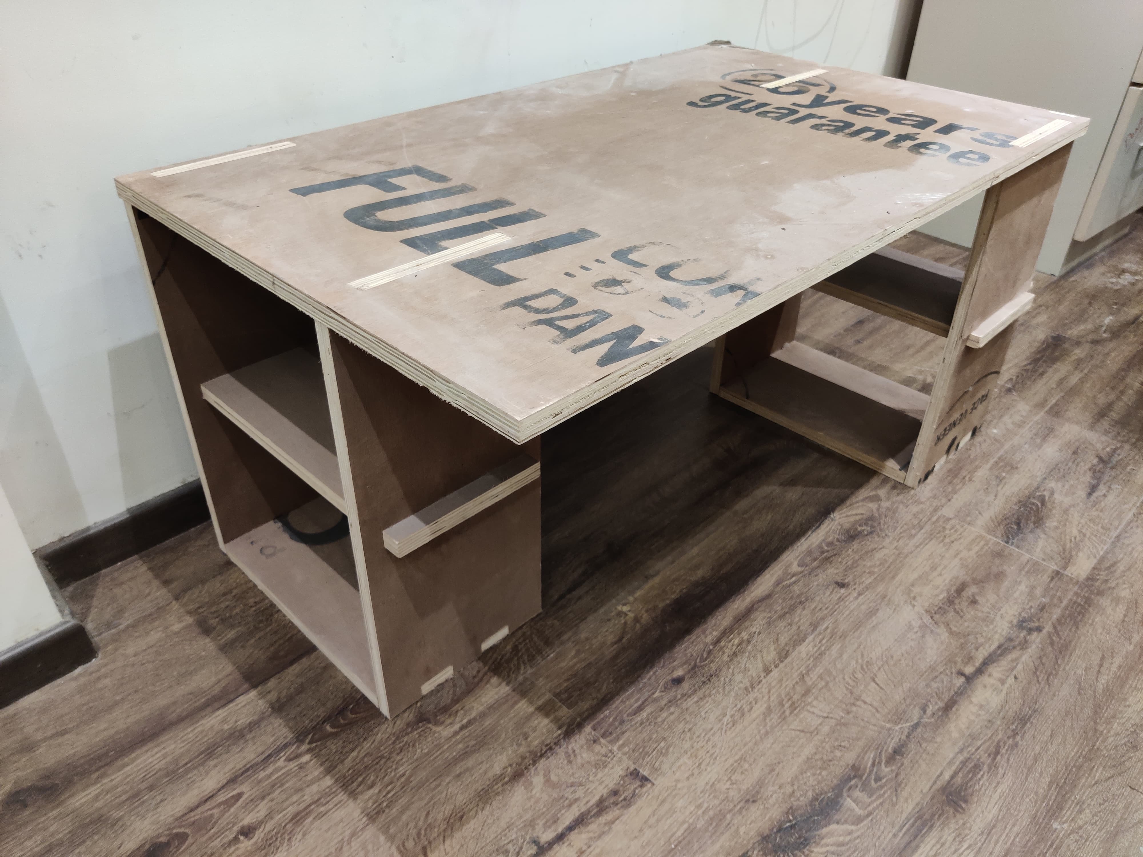
Assembly
After cutting now it's the time of assembling everything together.
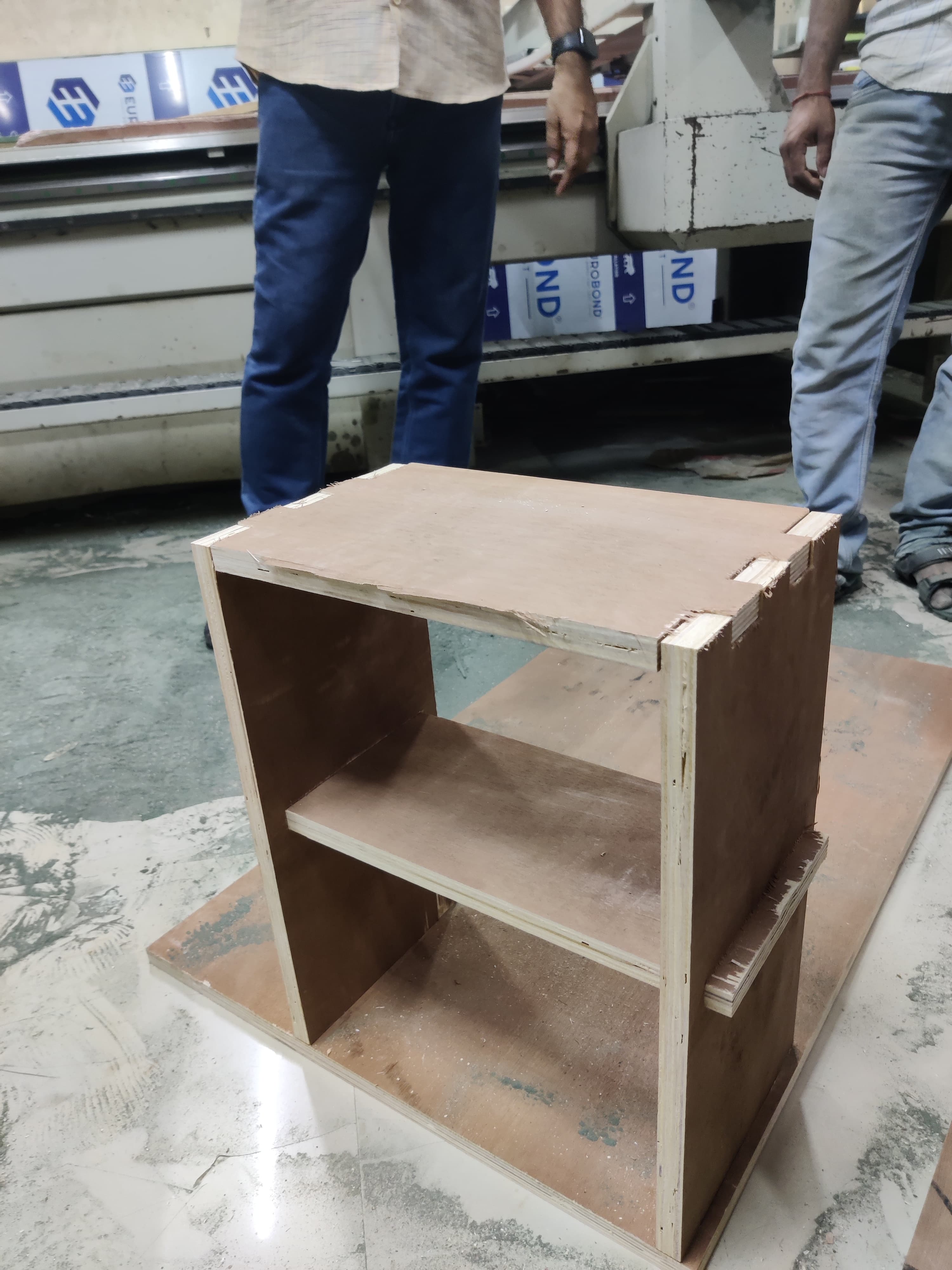
Hero Shot of 1st table
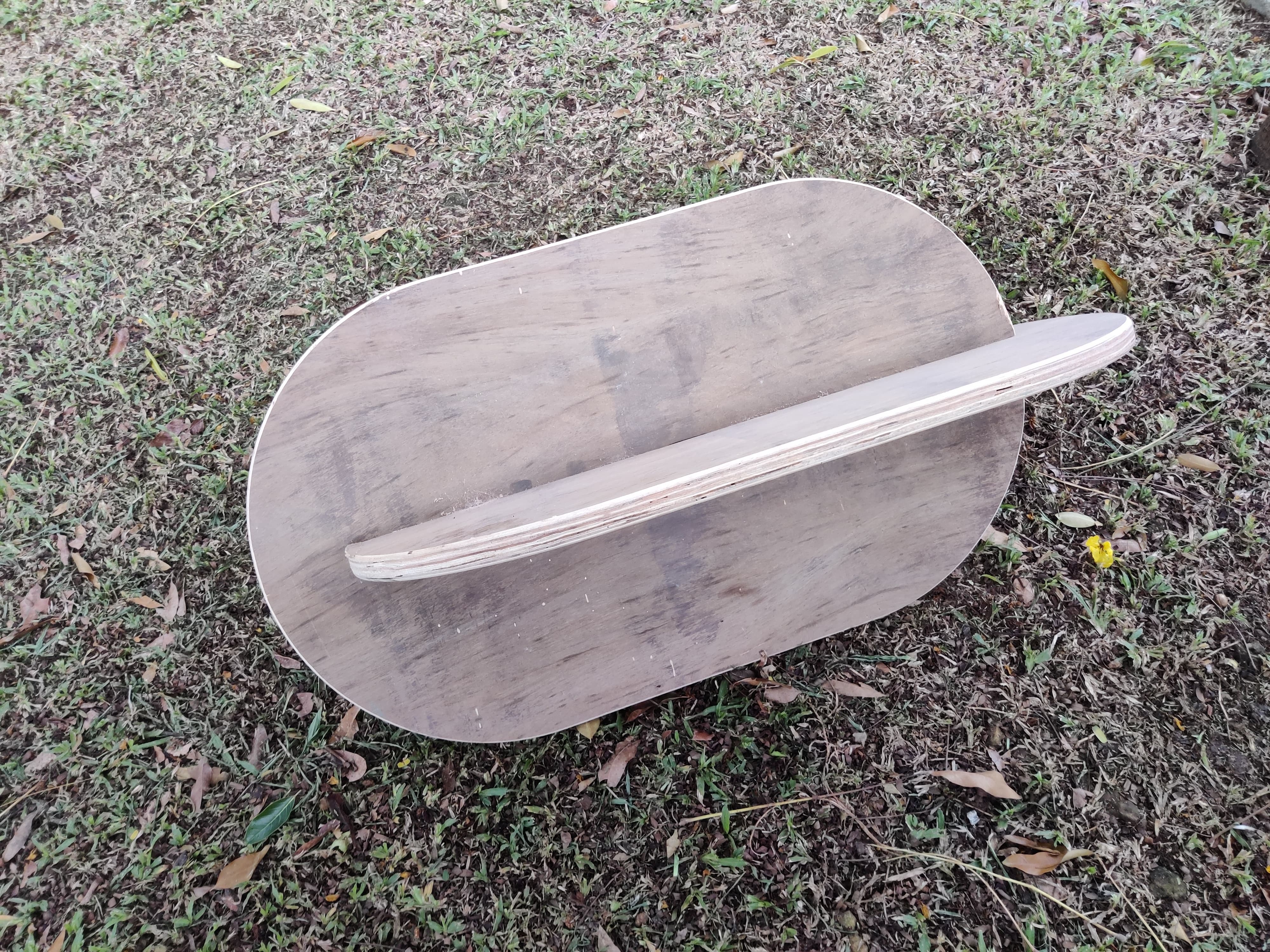
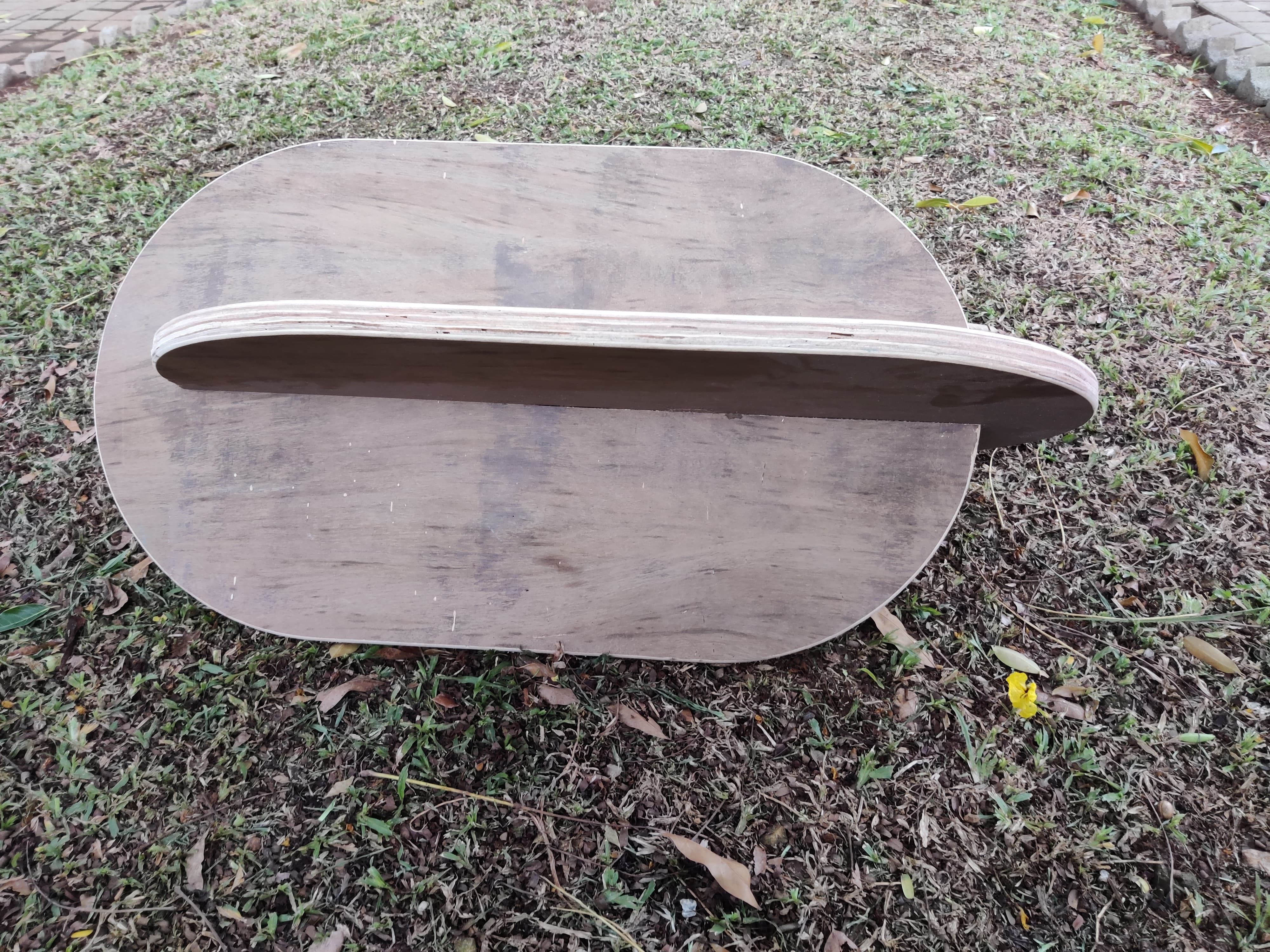
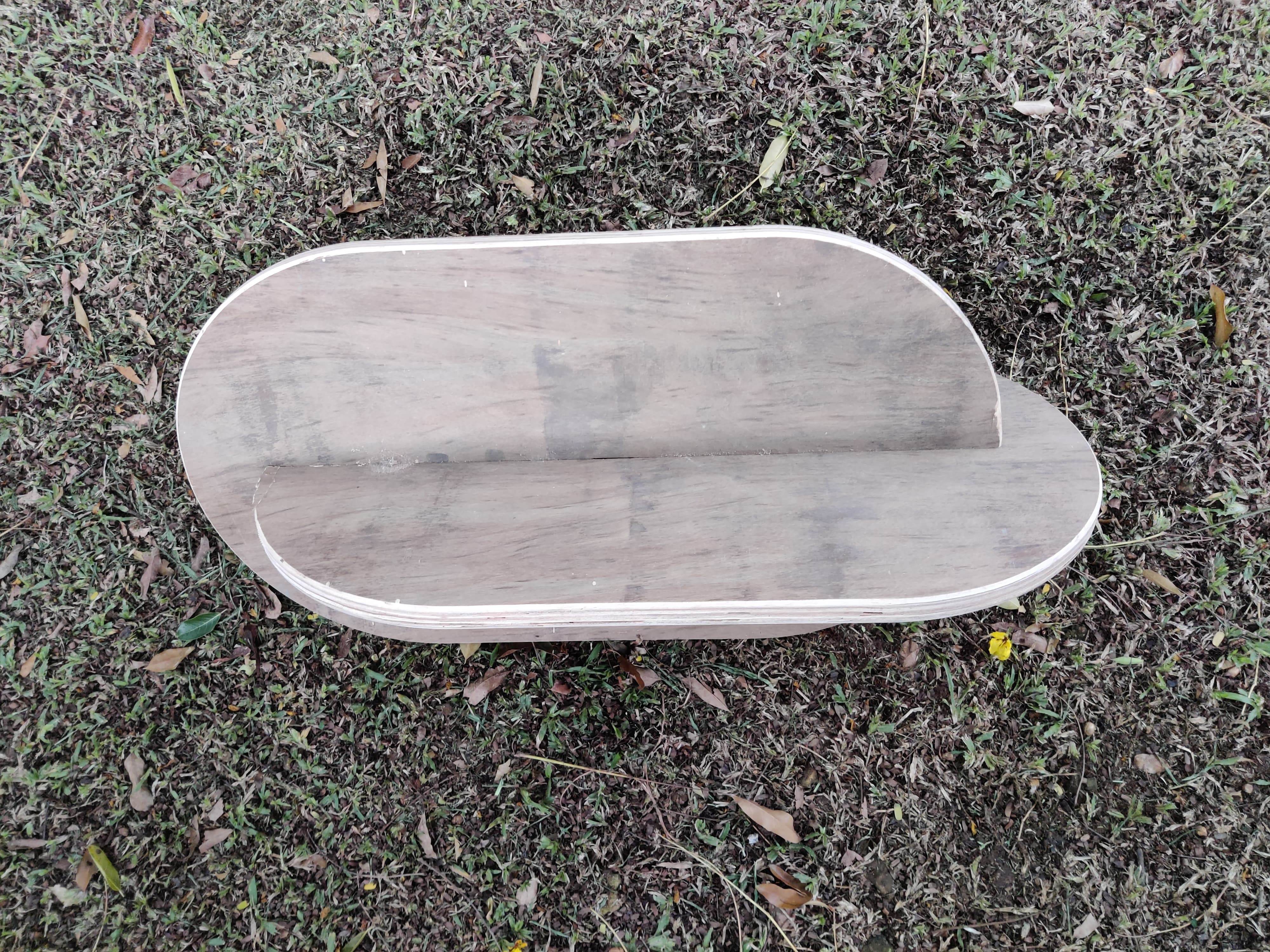
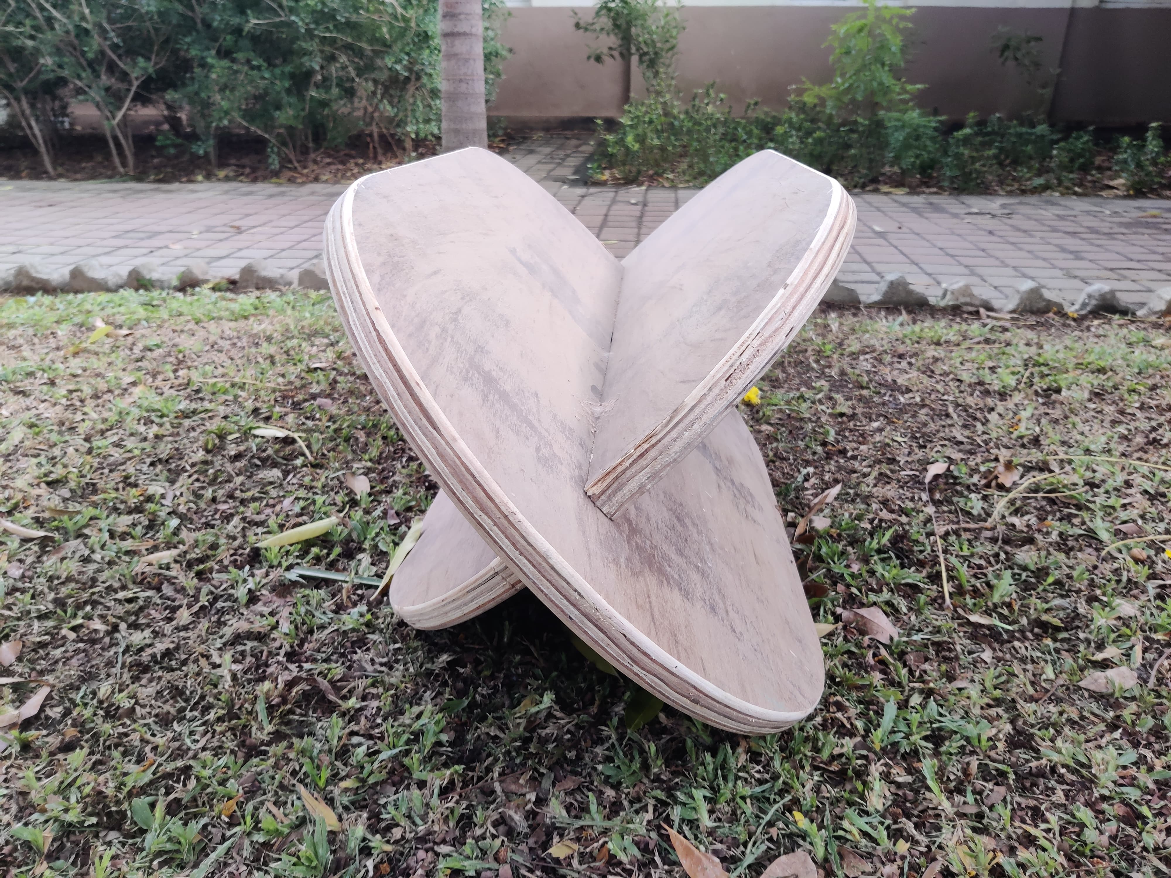
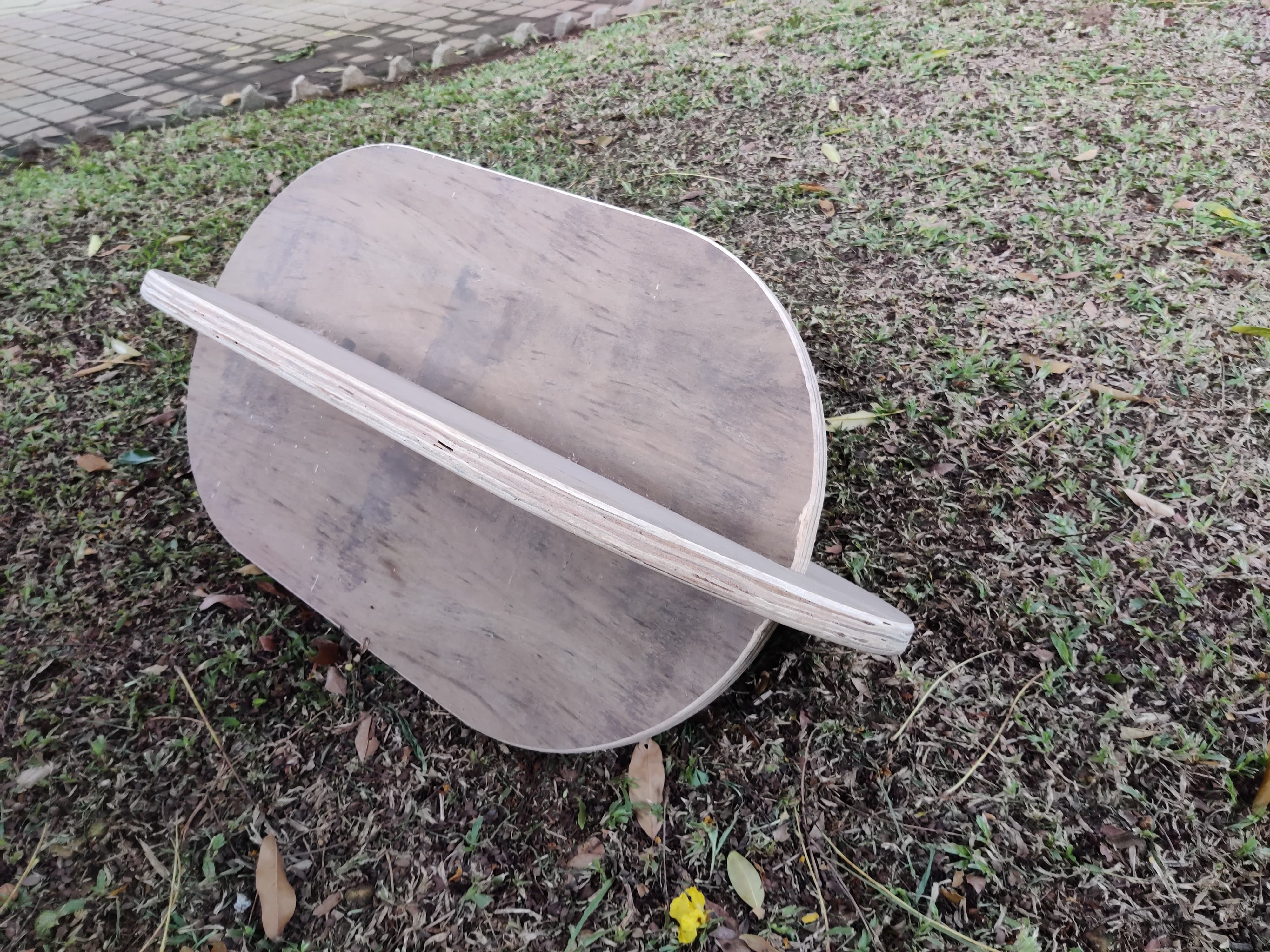
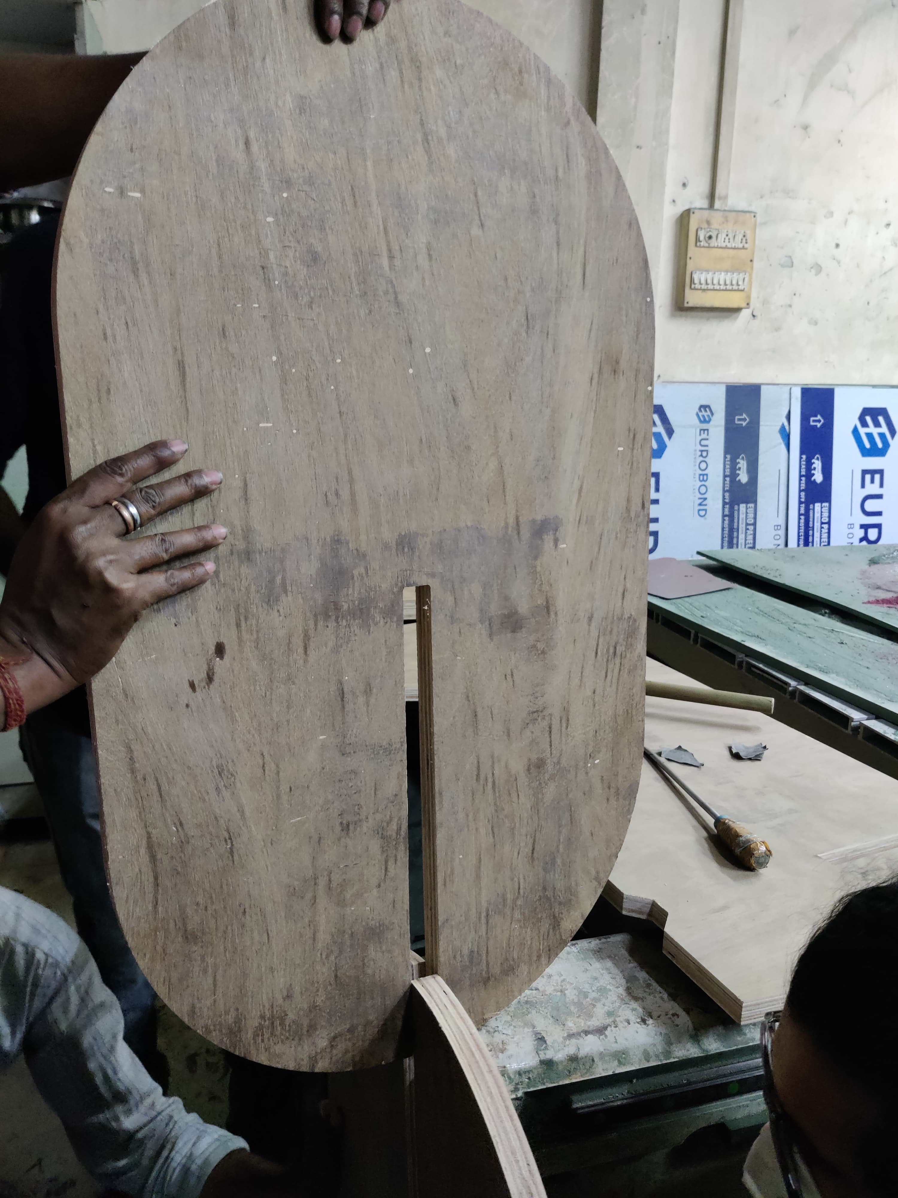
Hero Shot of 2nd table
Conclusion from this week
During Computer Controlling Machine Week, both group and individual assignments provided a comprehensive learning experience. As a group, we successfully completed lab safety training and tested runout, alignment, fixturing, speeds, feeds, materials, and toolpaths for our CNC machine. Individually, I designed, milled, and assembled a meter-scale table without using fasteners or glue, earning extra credit for including curved surfaces. This hands-on experience not only enhanced my technical skills in CNC routing but also deepened my understanding of safe and efficient machining practices, culminating in the successful creation of a complex and functional piece of furniture.
Design Files
18mm table dxf
18mm table step
25mm table dxf
25mm table step
Image Credits
All images of cover page are credited below:
https://images.app.goo.gl/3X6D2SJNceC3Smo9A.
https://images.app.goo.gl/Bth3oRPd9EzbbcAV6
https://images.app.goo.gl/6zxKAFz1GzxfGQEW9
https://images.app.goo.gl/EJ3AJ8CcXNx2uA4n9.
https://images.app.goo.gl/dew3JFAajwtr4F9TA
https://images.app.goo.gl/LUMELHCSMA7SDRoj6
https://images.app.goo.gl/dD6pQkvXrWNpu2Tm8
https://images.app.goo.gl/Vyphzx4a4KHxh6u3A