Week 4
Electronics Production
individual assignment
- make and test a microcontroller development board
- extra credit: personalize the board
- extra credit: make it with another process
Group Assignment
- characterize the design rules for your in-house PCB production process
- send a PCB out to a board house
Development Board Production
First of all was to establish the design rules For the Roland Mdx-20 milling machine. this I did By talking with my Instructor Andri sæmundssson and He confirmed that my node was infact using the same Tool as he was and this I borrowed this data from his student Page.
so provided this information was correct I was safe to assume that the 0.4mm would be a suitable trace width and spacing.
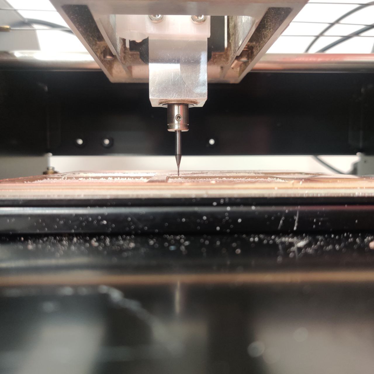
to set up the mill for to be ready to cut we put double sided tape on the back side of the FR1 material and stick it down as straight as possible on another piece of Fr1 already on the mill bed
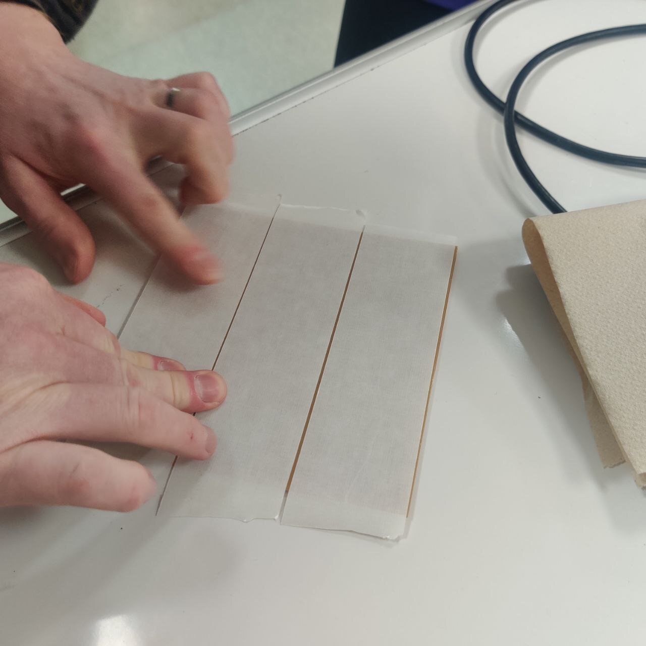
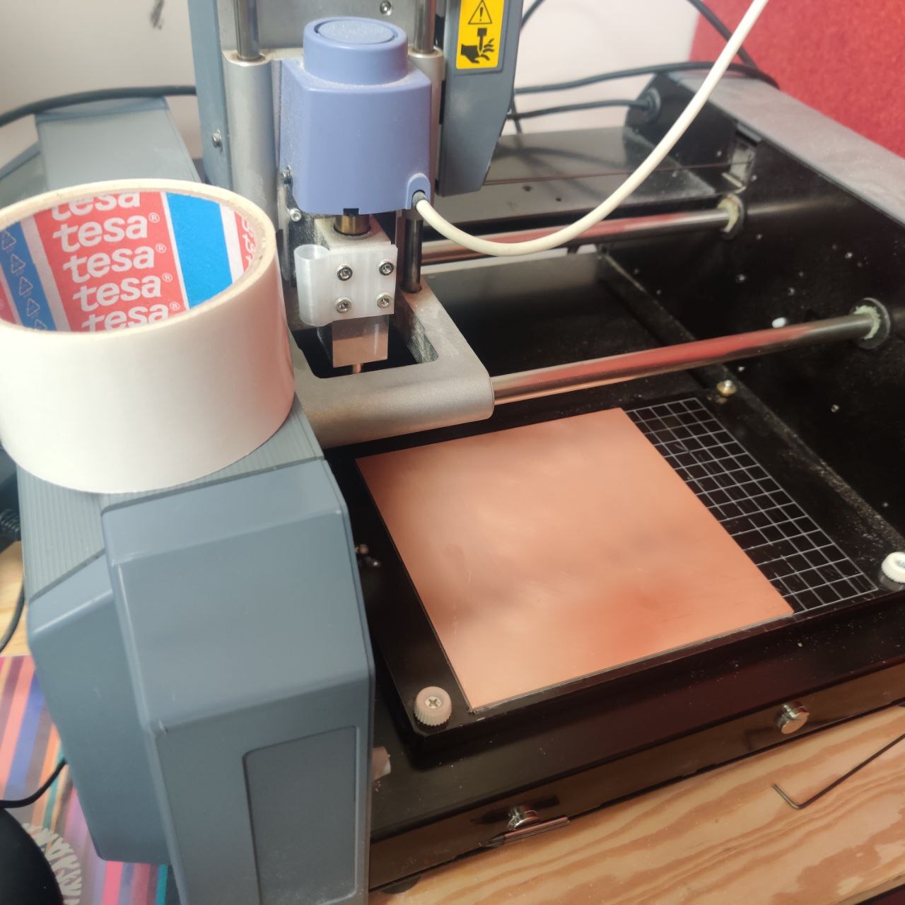
next was to set the X/Y to 10/10 to choose a spot 10mm into the workpiece so as to leave some room for error and then zeroing the Z axis. this is done by having the tool moove to your desired X/Y coordinates and lowering the bit by pressing and holding the down button on the mill.
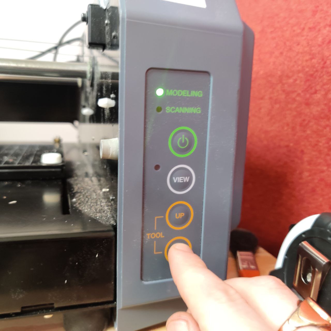
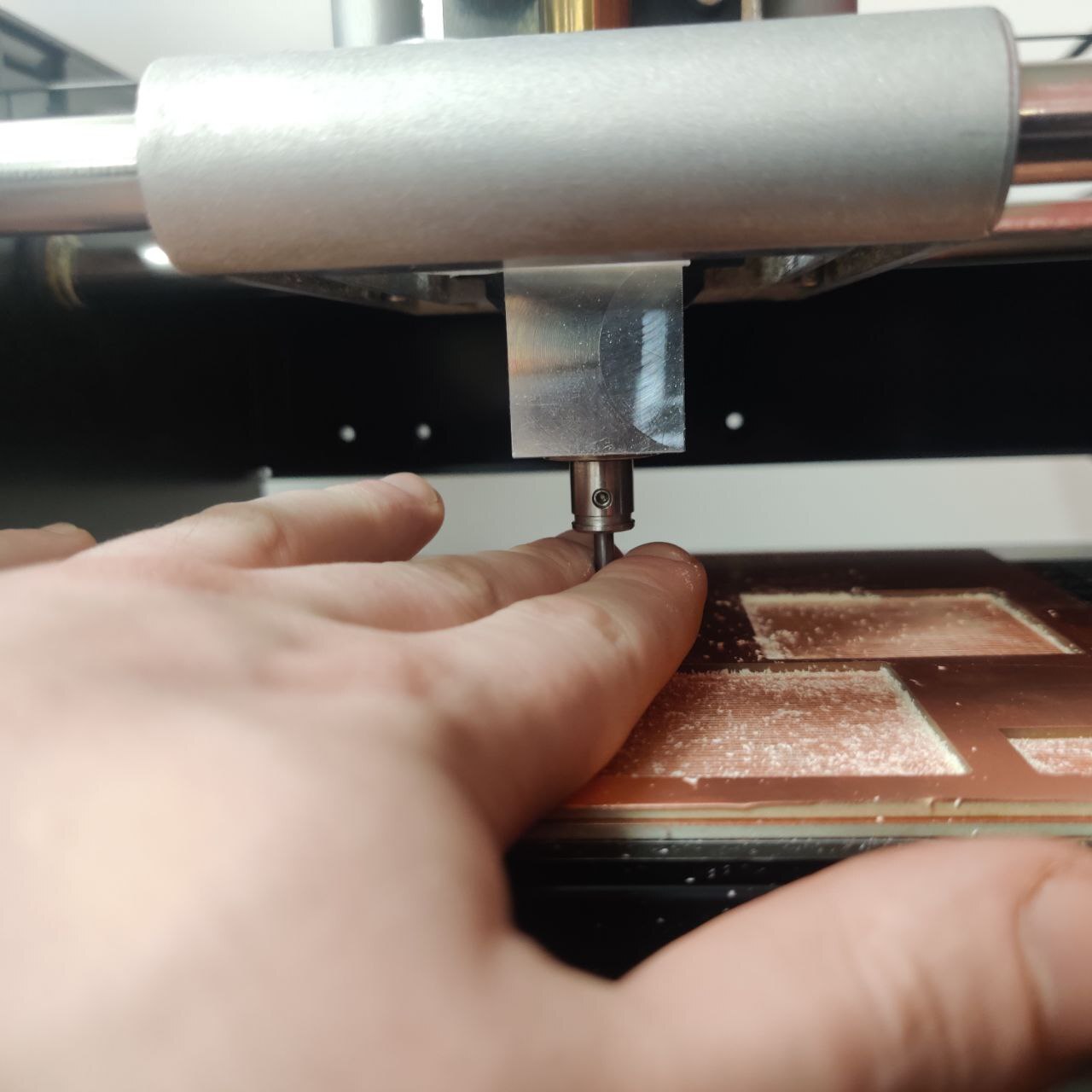
Next you simply loosen the little set screw on the side of the tool collet and gently guide to tool down to the surface of the workpiece. then you hold the pit down firmly to the workpiece and tighten the set screw again.
So as per Neils and the other Instructors recommendation I made the Quentorres Programmer board But I did have to make some modifications to it seeing as the lab in reykjavík did not have some of the same parts or parts with the same pitch.
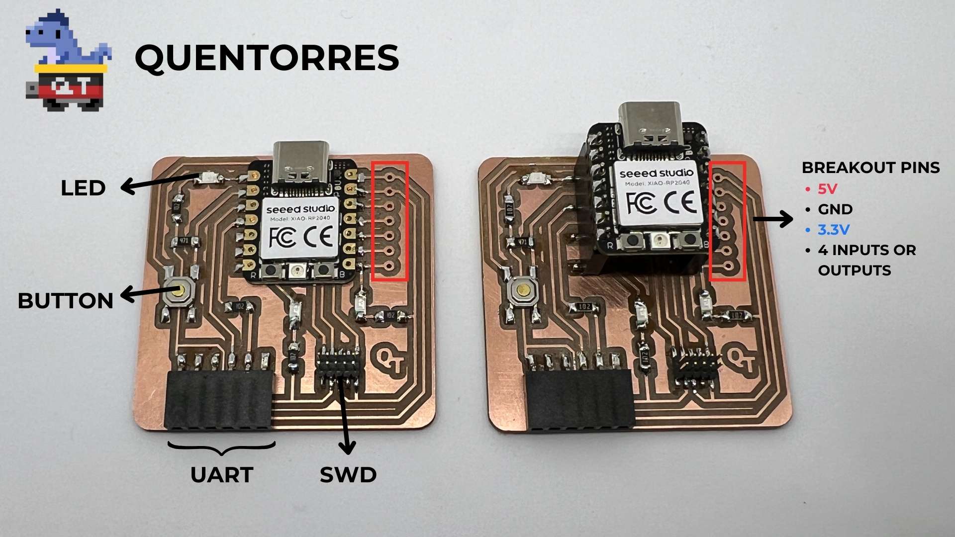
the changes I had to make were not too agressive. I really ony had to change the through holes for the breakout pins into solder pads for surface mount soldering.
then in the server for the mill I made sure I had the MDX-20 sellected, hit calculate and send and it started milling the quentorres developer board
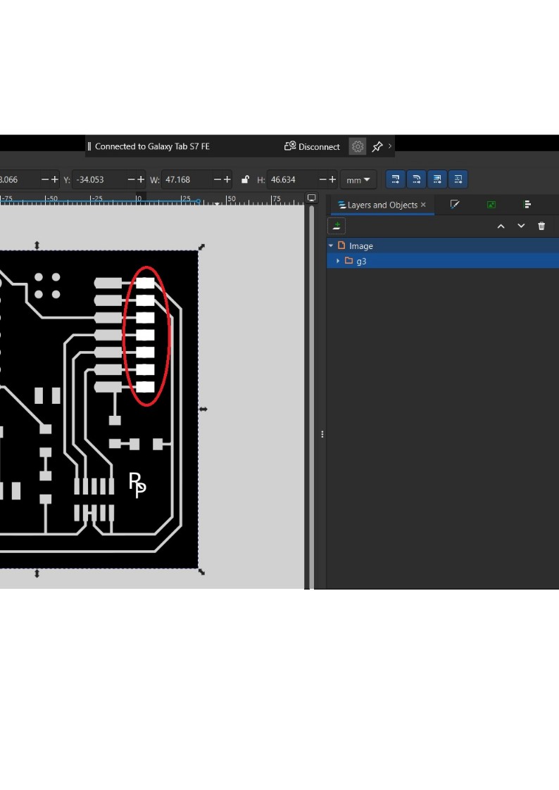
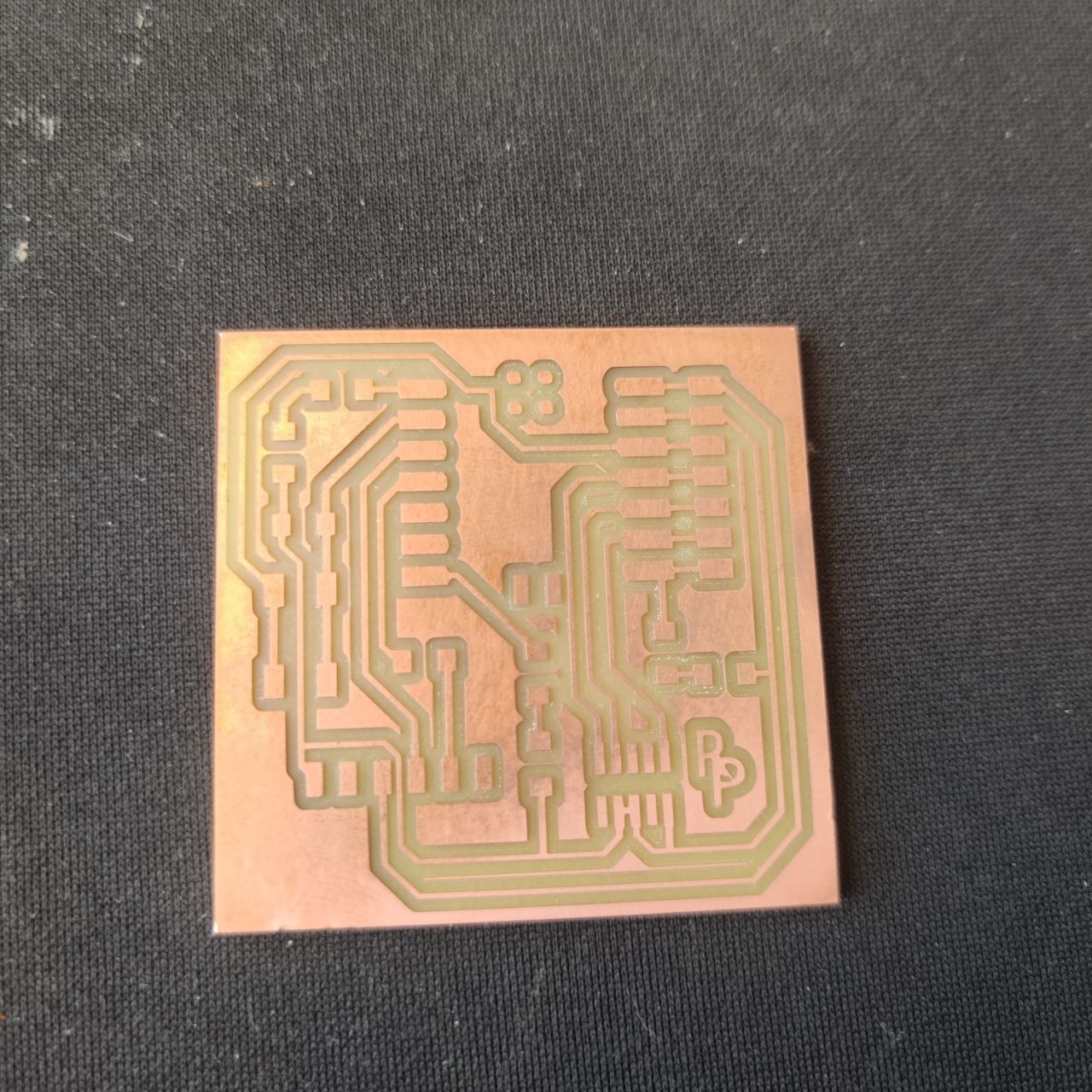
Now it was time to find the correct components for the quentorres and soldering them to the board. it was here that I realized that i had to also change the pitch on the SWD pins to 2.54mm because those were the only pins on hand.
I did this real quick and milled the new and improved board, then on to soldering, this was reletively easy as I have done quite allot of soldering before and know the process intimately, heating up boath the pad and pin with the soldering iron and carefully feeding in just enough solder to make a nice joint.
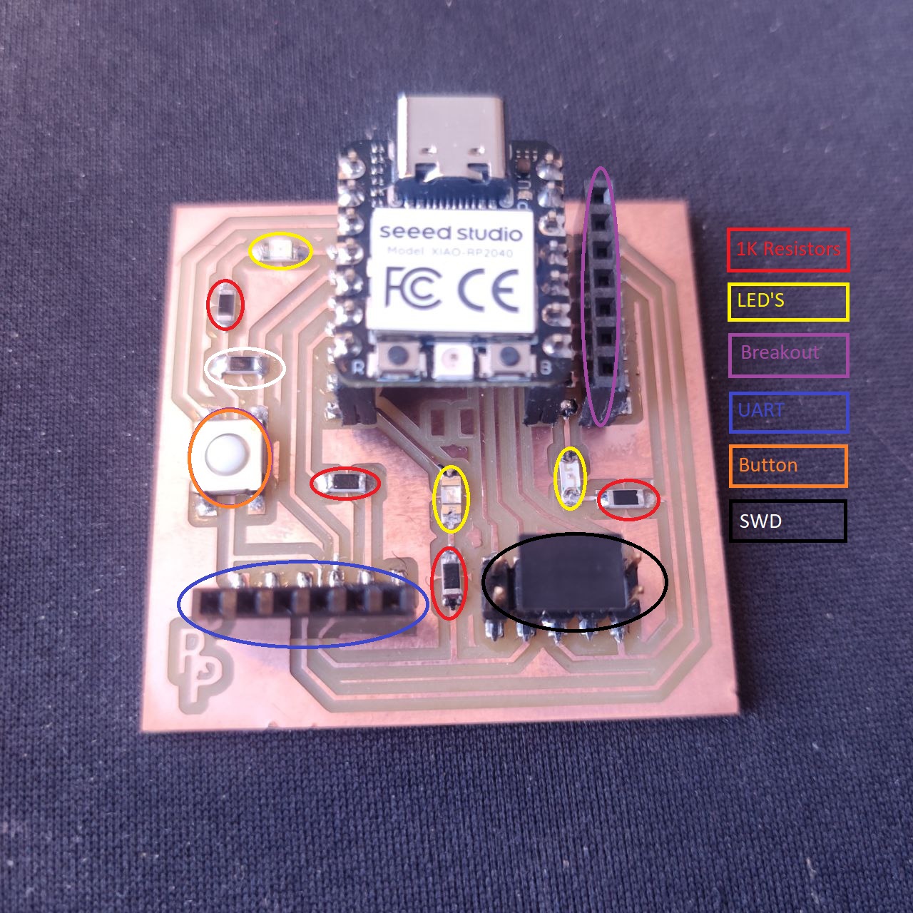
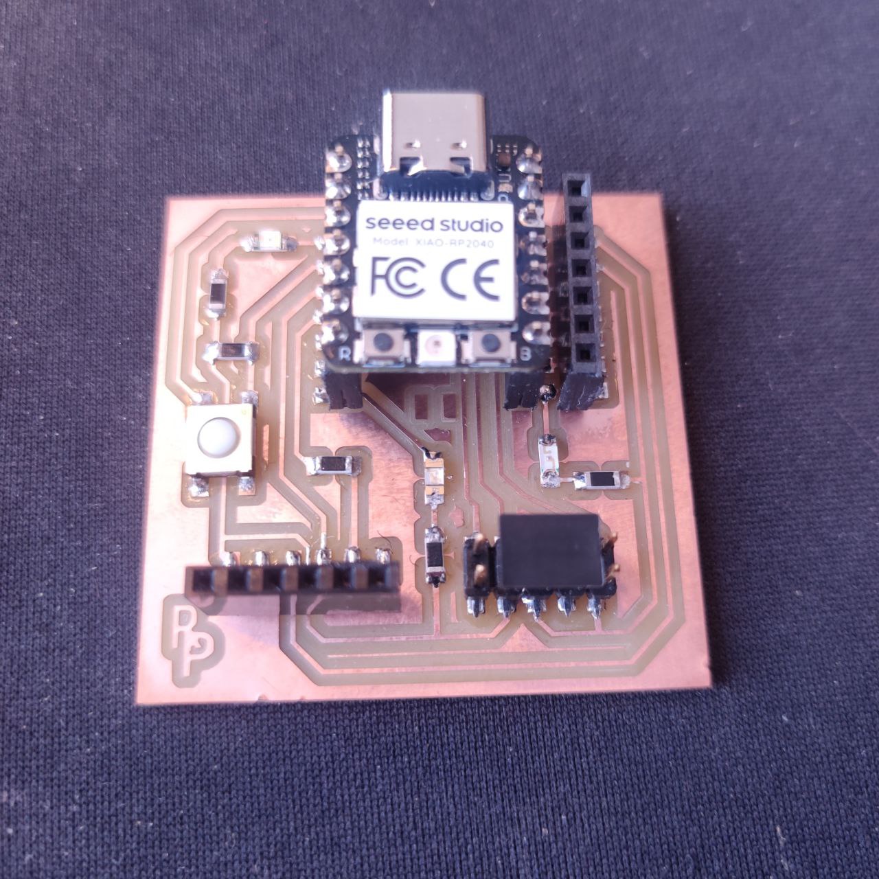
Now I wanted to try it out so I Followed the instructions provided Here and using code I found Here this resulted in me being able to turn the led on by pressing the button as shown in the video below.