Week 09: Output devices
Grupal Assigment
Understanding Power
We learned about the key variables in a circuit: Current (I), Voltage (V), Resistance (R), and Power (P).
Measurement Methodology
To calculate power, we needed to measure both current and voltage due to the inductive nature of motors. We used the following methods:
- DC power supply
- Hioki multimeter
- USB Current Voltage Checker
Measurement Results
Pololu 125:1 Metal Gearmotor 20Dx44L mm 6V CB
- DC Power Supply: 5.3V, 0.13A
- Multimeter: Nominal 0.126A, Peak 0.351A
Handson Technology 3420 DC Motor
- DC Power Supply: 12.1V, 0.54A
- Multimeter: Nominal 0.492A, Max 1.101A, Average 0.515A
TowerPro MG995 Servo Motor
- USB Current Voltage Checker: Peak and average current measurements
- Multimeter: Standby 6mA, Under load 0.774A
Kicad Board Design
For this specific task, I decided to create a multicontact due to the lack of pins in my previous PCB designs.
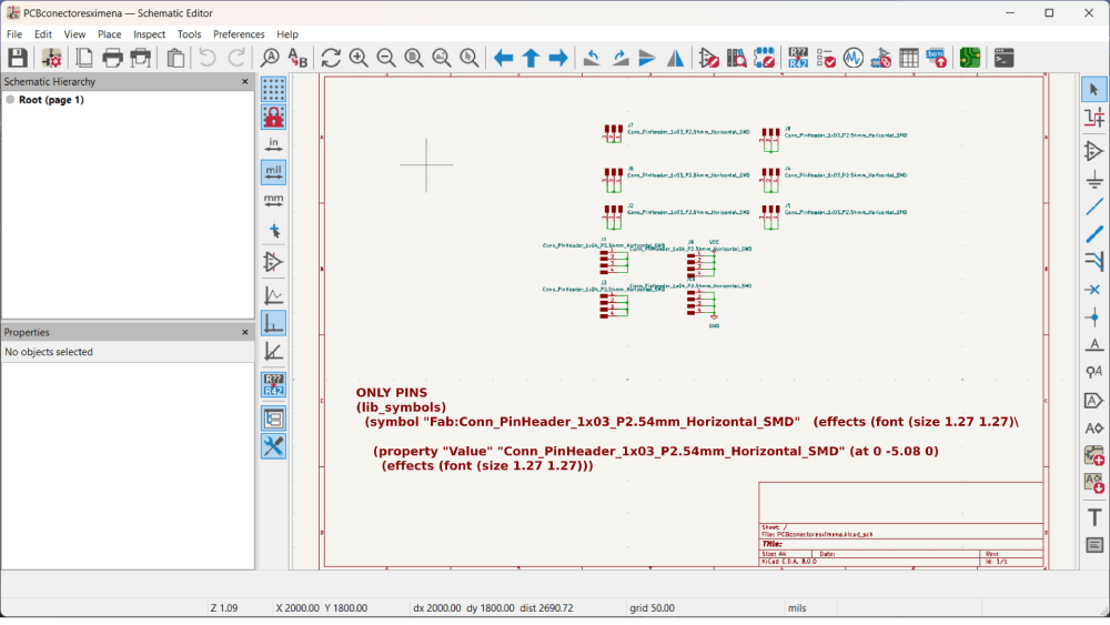
- I only used pins in the diagram, so I added as many as I needed from the library
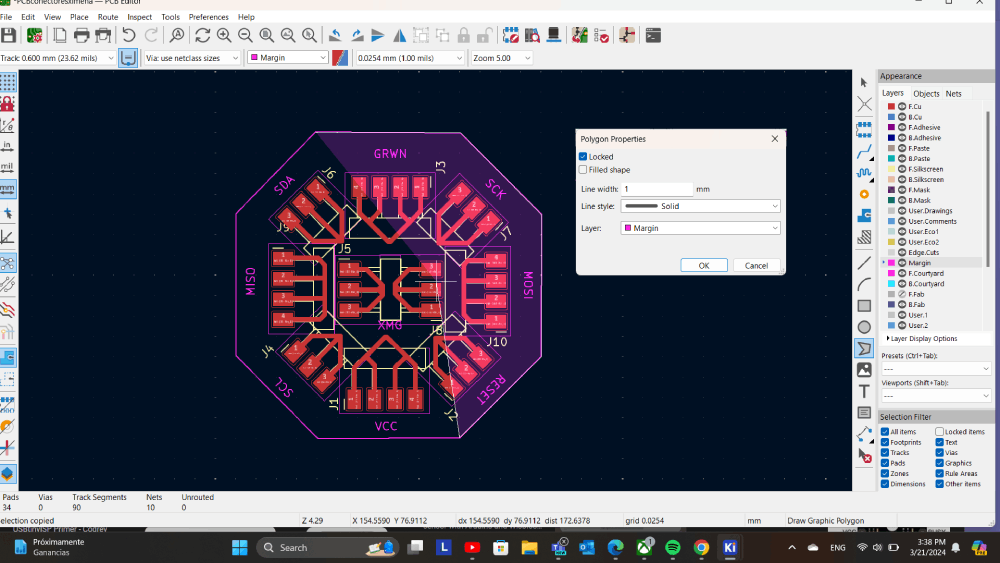
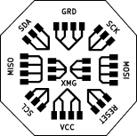
- Then I designed how they would be connected. Due to the number of pins and their intended use, I decided it would be best to create a polygon with two additional sets of pins in the middle.
- I also added labels to make it easier to identify where the pins should be connected to all the devices.
- Finally, I added the margin, as seen in previous designs.
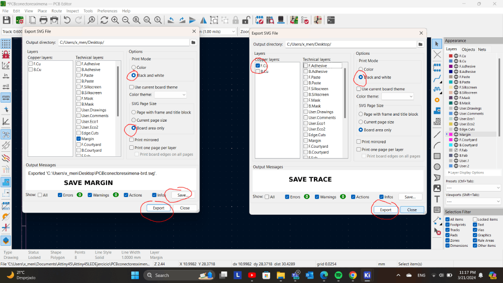
- And to send the cut we first create the trace saving only F.Cu.
- Then margin saving margin in svg.
MODS archive
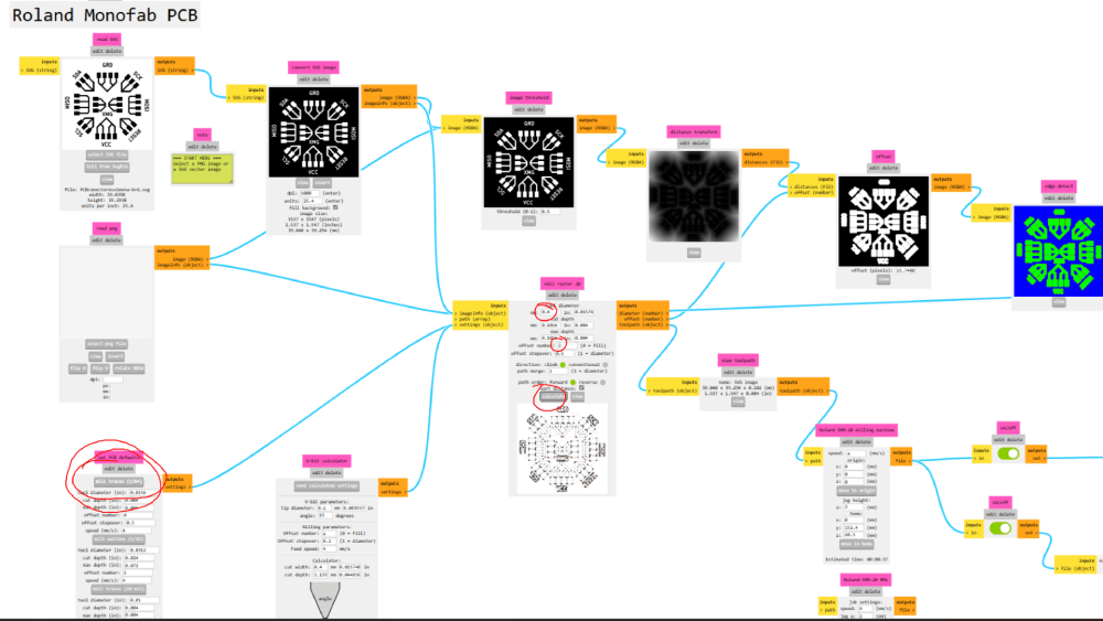
For mods, we followed the same process as in past weeks: placed the image of the corresponding traces to cut them on the copper board.
Steps:
- Select measurements from past weeks.
- Apply an offset of 2.
- In the section of the Roland SRM-20 milling machine, set the origins to 0.
- Click "Calculate". Once this is done, an RML document will be generated to be entered into the program.
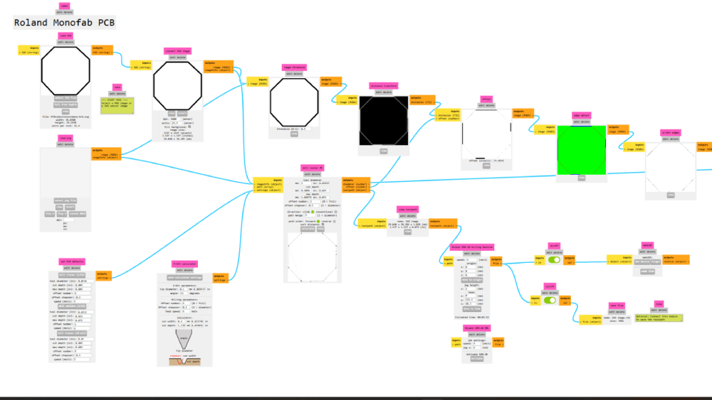
For cuts only, the process needs to be changed:
- Invert the image.
- Instead of selecting "Mill Tracers," choose "Mill Outline."
- Change the "Tool Diameter" to the diameter of the tool to be used, which is 0.8 in this case.
- Click "Calculate". Create the RML document.
Mods for the trace
Mods for margin
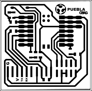
These are the images of the final PCBs I'm using. Please note that they are inverted. You can use these images for cutting a PCB instead of using the SVG.
Cutting PCB
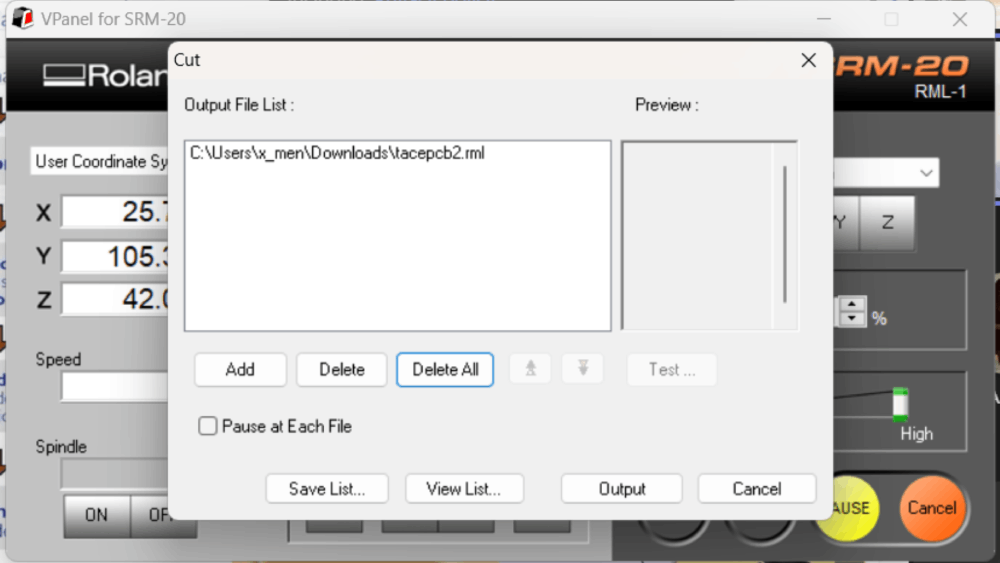
To start the cut, please find the edge X, Y, and Z.
Then add the files that we previously made in "mods".
- Click on Cut.
- If there's an archive, click Delete all.
- Click Add and select the first trace.
- Click Output and let it cut.
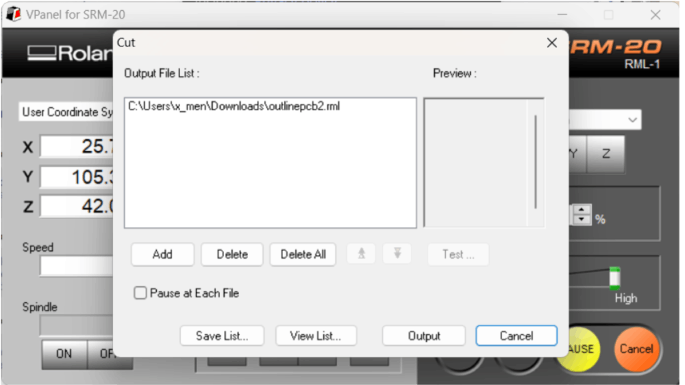
Repeat this routine with the margin and that's it!
- Repeat the above steps for the margin.
Program OLED Display
Is a monochrome (black/white) OLED graphic display with 128 pixels wide and 32 pixels deep. It can be controlled for I2C protocol and a 3.3v.
Arduino
Steps:
- Install the Libraries: Sketch -> Include Library -> Manage Libraries.
- Install SSD1306. Install all, including the GFX library.
- Open the examples to see what you can do with it.
I2C
I2C stands for Inter-Integrated Circuit and is a protocol to communicate with one or more chips. It consists of 2 signals: SDA (Data) and SCL (Serial Clock).
The OLED display works with I2C communication so we need to conect the microcontroller using this exact diagrams
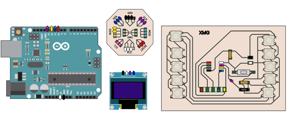
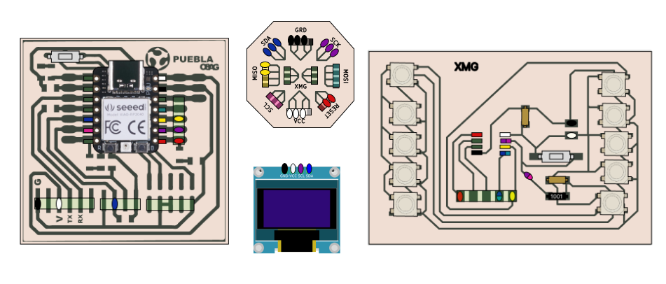
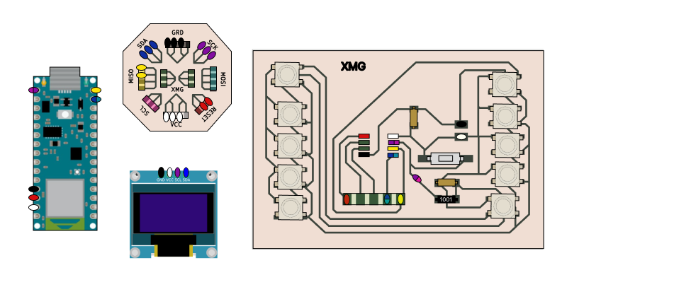
Just like it is shown in the diagram or you can follow this images, due to de complexitie of conection what I can recomend you is to conect each port with a different color , for example all GRD conections in black, all Voltage conections white, SCL pulple ans SCK blue
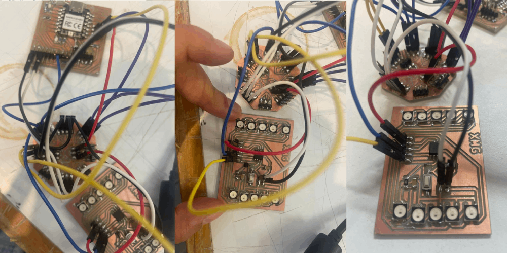
First example OLED
in hear I conected de OLED uisng SCL y SCK en los demas puertos usando the OLED example in Arduino> Libraries> Examples> OLED examples
What you can do in the OLED display:
Write text
Scroll text
Add fonts
Draw shapes
Invert colors
Display images
Create your own code
Image creation
We have 2 options:
- Create our own image
- Upload an image from the web
Create animation using reference
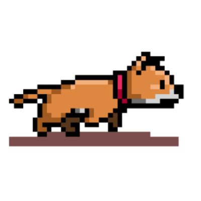
First I surf the internet looking for an image.
-
Then you can use any platform that you want. I use Photopea and configure the canvas to 128 x 32 pixels.
Then painted the little dog using this animation as reference.
You can add more but this animation works with 3 imgs
Once we save the image, we go to a converter from image to byte. I used this one.
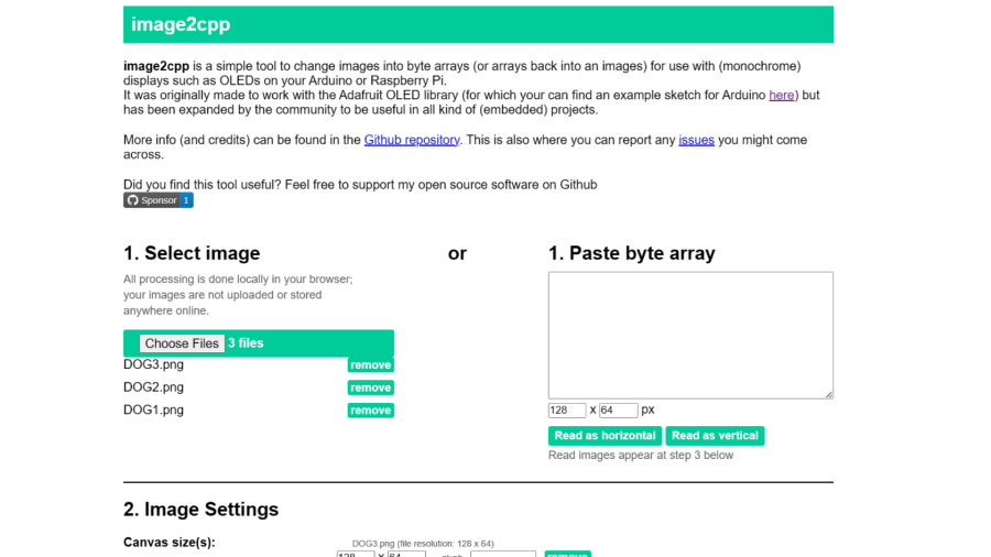
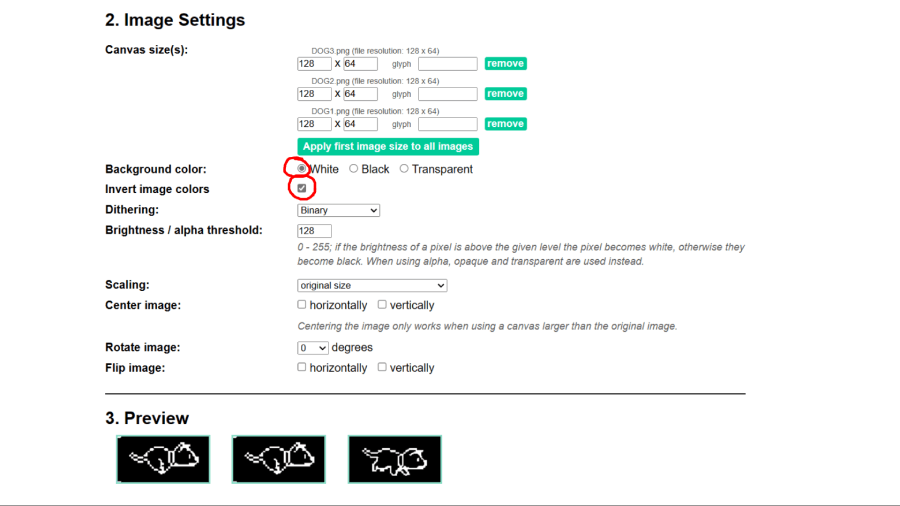
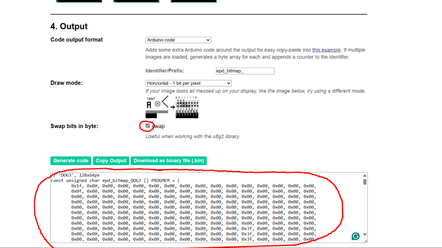
If we want to use animations and cut down on programming, we also need to download the library from https://github.com/olikraus/U8g2_Arduino. Follow the example at https://wokwi.com/projects/374294166215201793Or simply copy this code and edit the code where it says Insert code and add the one you get in the page above .
Quick Video Tutorial
This is the diagram that I used to charge the program that you see in this video
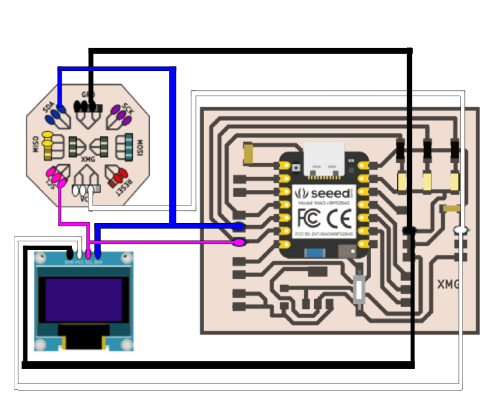
So once you have follow this diagram above you can proceed to use the code above or download the archive DOG Animationto follow exactly how it says in the video, dont forget to select the correct microcontrollerand the correct PORT.
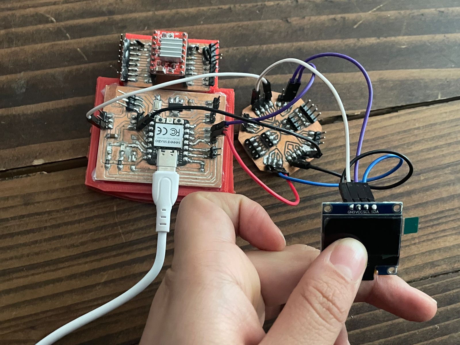
Final Results
Files
Reflection Summary
This week, I delved into PCB design using KiCad, focusing on creating a multicontact PCB to accommodate a variety of components. I used pins from the library and connected them with polygons, adding labels for clarity and margins for accurate cutting.
Challenges and Solutions
Designing the multicontact PCB presented challenges in organizing the numerous pins and ensuring correct connectivity. I overcame this by carefully planning the layout and using polygons to group pins logically. Exporting the design for milling required adjusting the settings to ensure precise cutting.
Working with the OLED display and programming it via Arduino posed another challenge. Installing the necessary libraries and understanding the I2C protocol were essential. Creating custom images and animations for the display involved converting images to byte arrays and utilizing external libraries.
Future Applications
The skills learned in PCB design, PCB milling, and programming an OLED display are applicable to future projects involving microcontroller-based systems and graphical interfaces. These skills are fundamental for developing more advanced projects that require custom PCBs and interactive displays.
Mastering KiCad for PCB design and OLED display programming will enhance my ability to prototype and innovate in electronics, enabling me to create functional and visually appealing electronic devices.

