Computer-Controlled Machining
Here its our group assigment: Week 7What I learned from the group assigment:
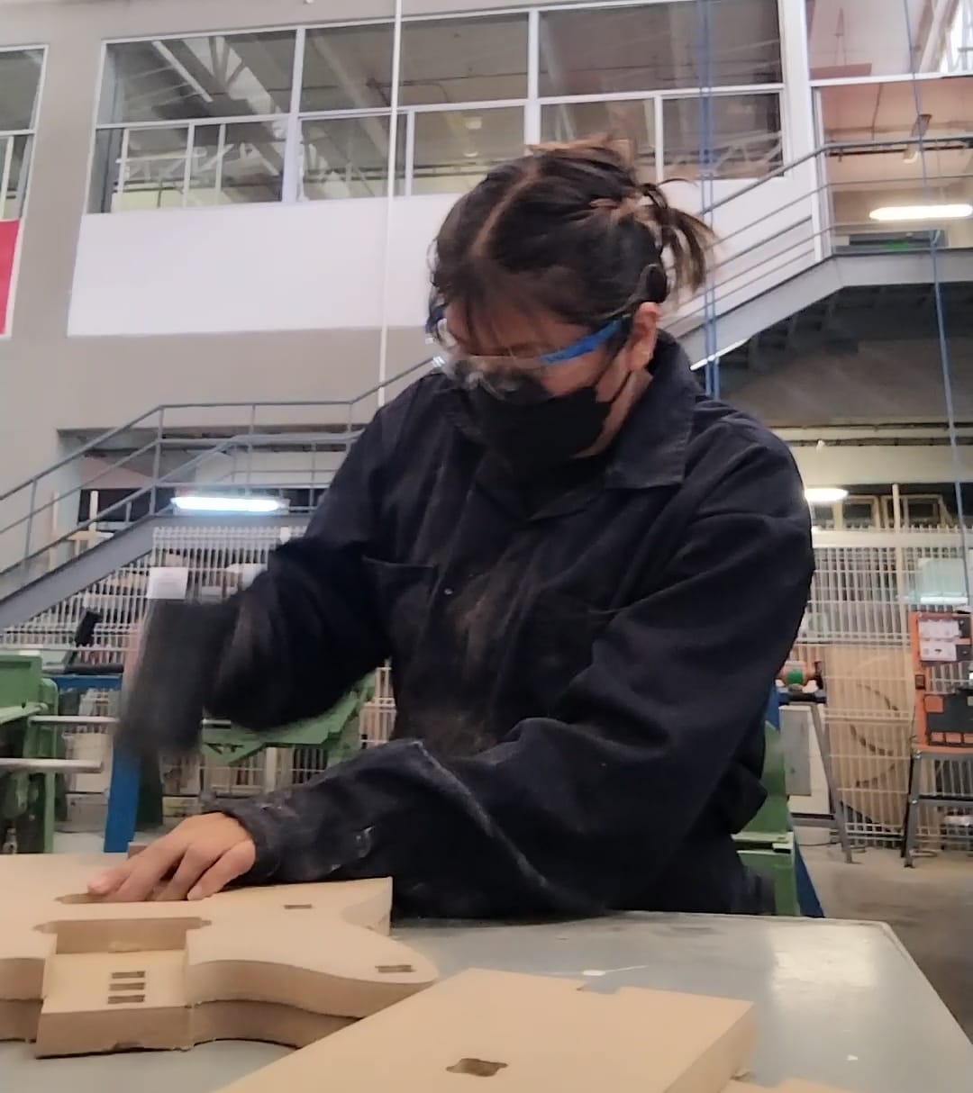
- Safety is really important so make sure to use: safety googles, noise protection headset, lab coat/ overalls, no hanging accessories, no shorts, safety boots and breaking mask.

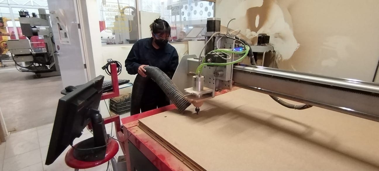
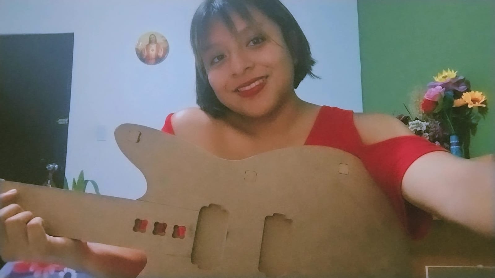
Here is an image of me with the necessary protection.
- When the machine is starting to operate, the operator should: remain attentive, do not wear gloves, close the door and do not put the hands near the cutting area.
- The floor must be clean, keep distance from the machine, make sure the cutting tool is colocated correctly and make sure everything is well positioned.
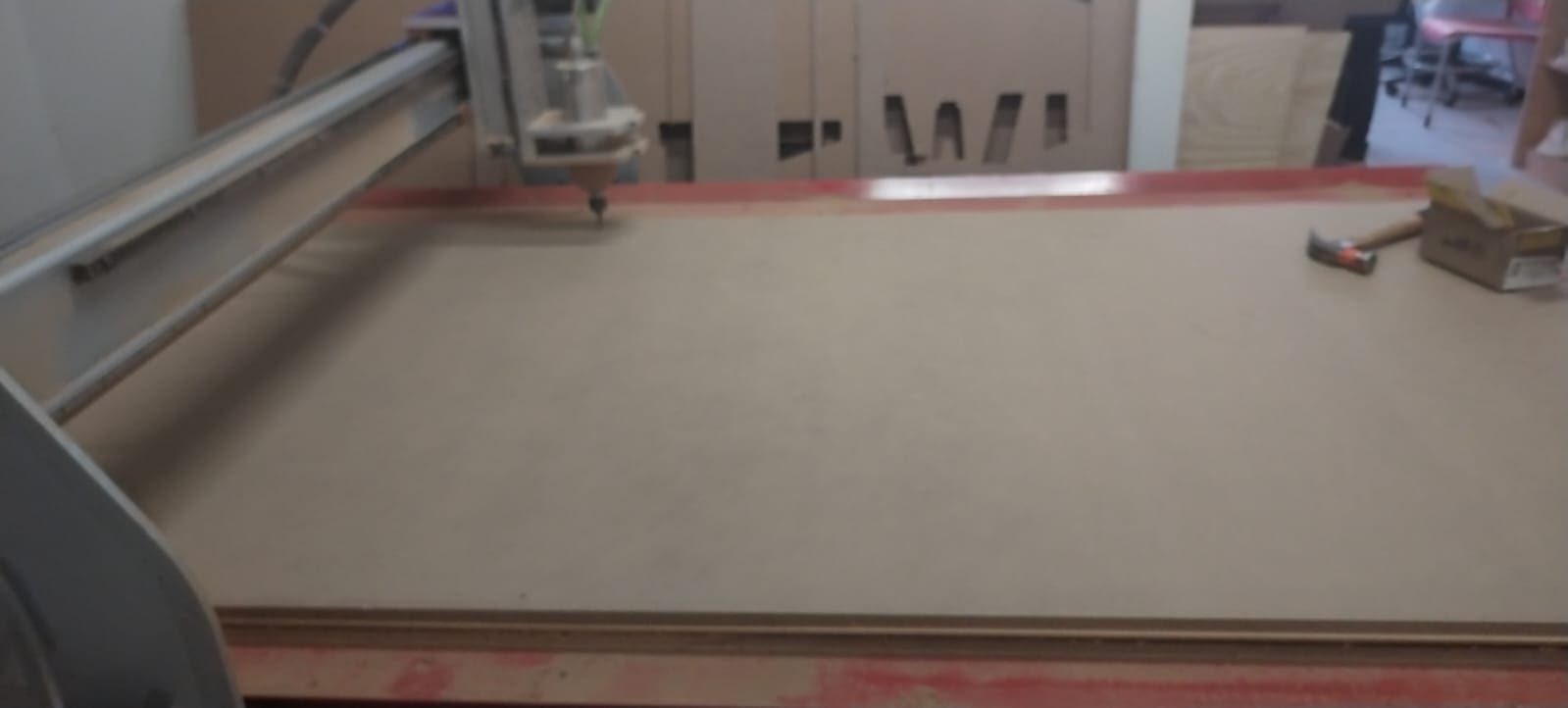
- In this Fab Lab Puebla, there are two CNC routers:
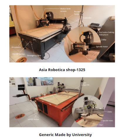
Here is an image of both of them:
- There is a various list of possible materials: ABS,acrylic, ALUCOBOND, aluminium, copper, estirene, tin, solidwood, softwood, hardwood, mdf, plywood, veneered, nylon, resins, etc.
- The runout test: a Starrett gauge was used for measuring the concentricity of the spindle/cutting tool, first with the spindle off, then turned on. This measuring gauge has a range of 0.01mm and after the tests, no variation was found.
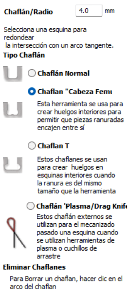
- Design rules: it is necessary to add “dogbones" or “T-bones” which are a slight modification of the mortise, the hole where the assembly is tight and well adjusted.
- Fizture:The material is fixed with a clamp that passes through the different canals in the machine bed.
Design
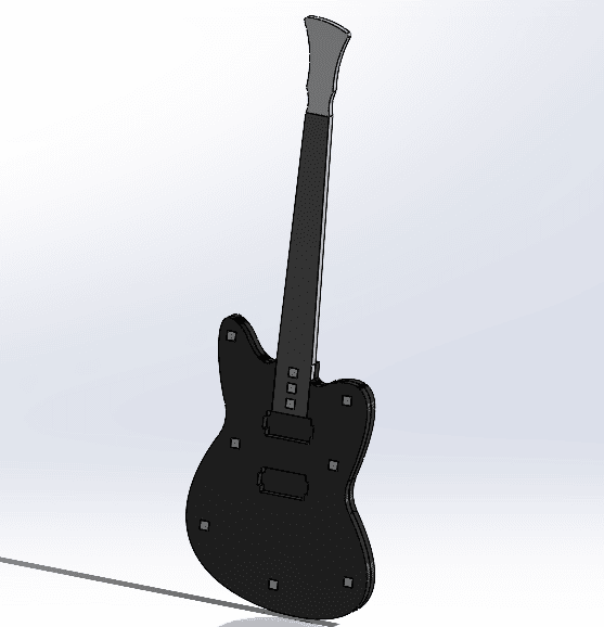
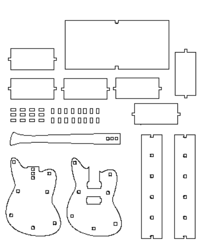
- Everything was designed in SolidWorks, because I am really used to the inteface and it's tools. I took the proper measurements for a guitar I have for my boyfriend, and for the organizer I took the measurements from the space I wanted it to be.
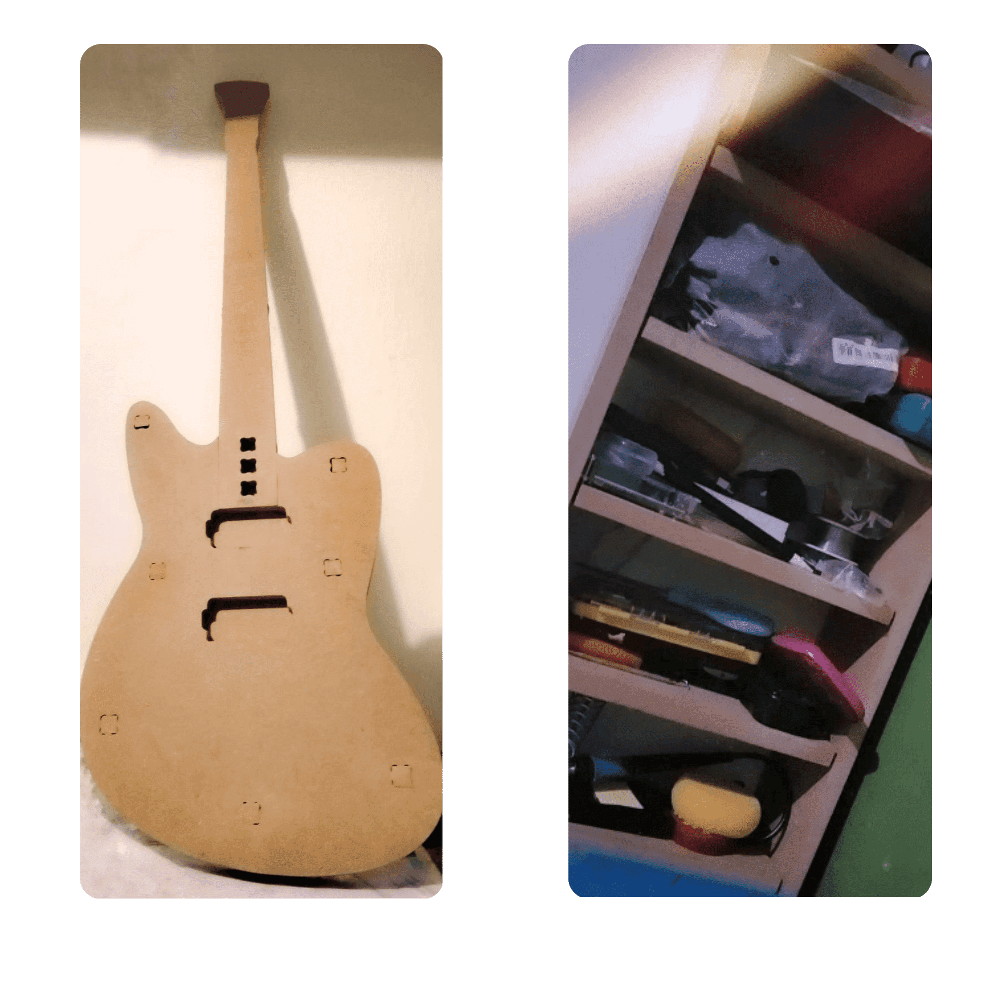
- The first idea behind the project was to attempt designing an electric guitar. Having access to one, I could disassemble it and use its components as a reference to generate a design. This would allow me to recreate the guitar in the future using different materials and easily program it for manufacturing.
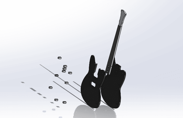
Its dimensions are the same as a real size guitar, in this case, 1m 10cm of height and of the narrowest part of the guitar, its width is 35 cm.
- The second idea stemmed from the fact that there was still some leftover space on the table we were provided with. Upon noticing that many electronics items were clustered in one spot, I decided to create a shelf to better organize everything.
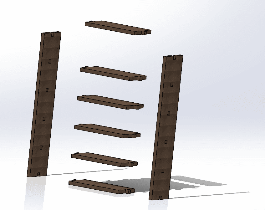

This design was kinda extra, because after learning everything from manufacturing the guitar, I could more easily do other things. The dimensions of this organizer is 60cm of height and 28 of width.
Vcarve
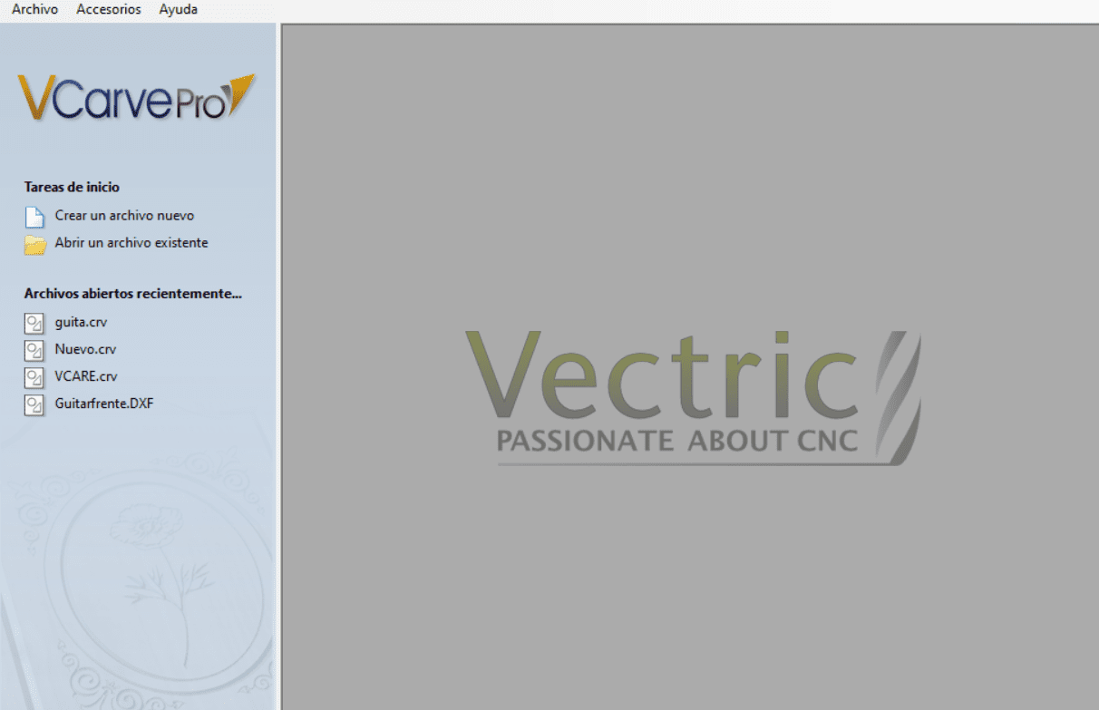
VCarve is a software package developed by Vectric Ltd. for creating toolpaths and generating CNC code for cutting, carving, and engraving designs. It offers a user-friendly interface with features tailored for woodworking, sign making, engraving, and more. You can create or import 2D designs, define material dimensions, and generate various toolpaths including V-carving, profile cutting, pocketing, and drilling. The software provides simulation and preview capabilities to visualize the machining process before sending the job to the CNC machine. Additionally, VCarve can generate machine-specific CNC code (G-code) for compatibility with a wide range of CNC machines, making it accessible to users with varying levels of experience in CNC machining and design.
-
Launch VCarve: Start by opening the VCarve software on your computer.
-
Create a New File or Open Existing Design: Depending on your project, either start a new design or open an existing one.
-
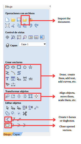
Design Creation: Use VCarve's design tools to create or import your design. You can draw shapes, import vectors, add text, and more.
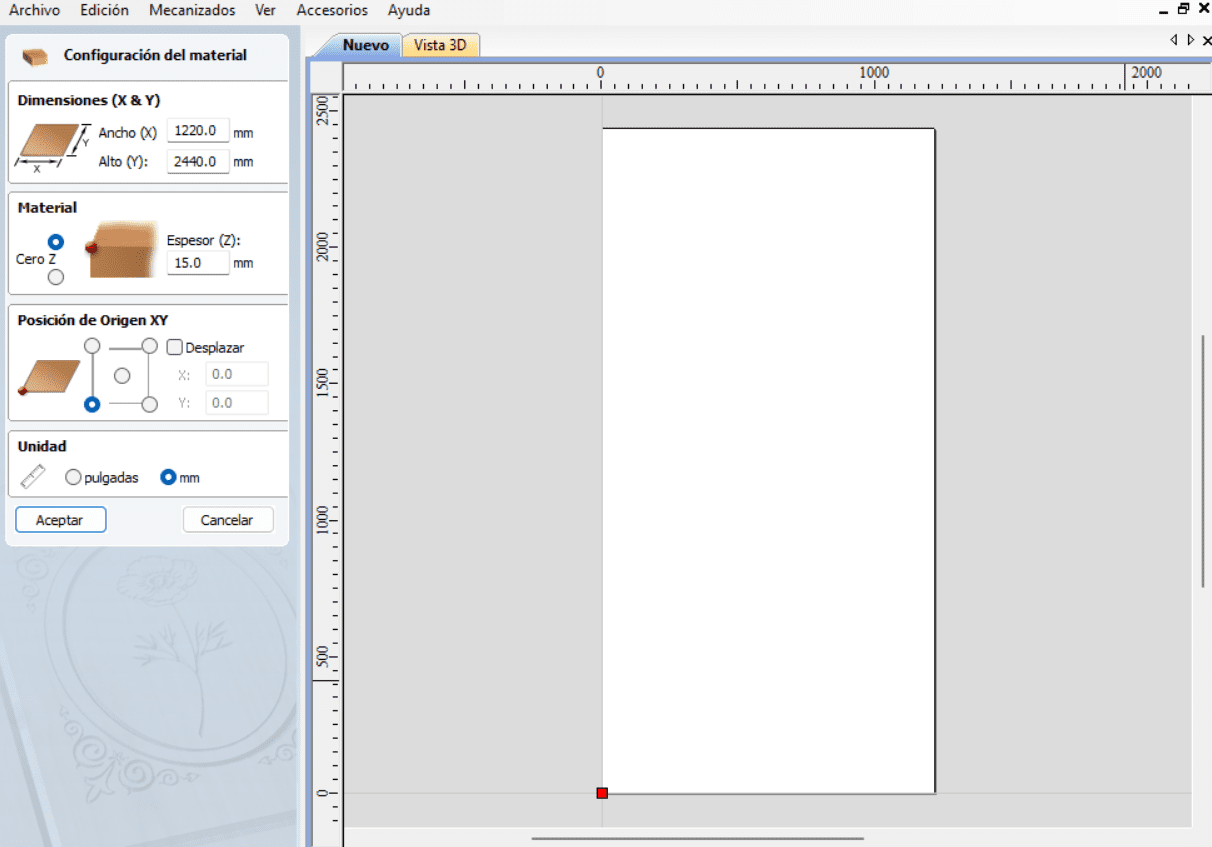
- Toolpath Setup: Set up your material dimensions, thickness, and other relevant parameters.
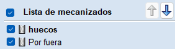
- Vector Selection: Choose the vectors or shapes you want to cut.
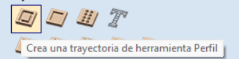
- Toolpath Generation: Select the type of toolpath you want to use, such as profile cut, pocketing, drilling, etc.
- Tool Selection: Choose the appropriate cutting tool for your job.

- Toolpath Parameters: Set parameters such as cutting depth, spindle speed, feed rate, etc.
- Preview Toolpaths: Before sending the job to the CNC machine, use the preview feature to visualize the toolpaths and check for any errors.
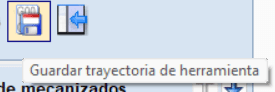
- Save Toolpaths: Once satisfied with the toolpaths, save them in a compatible format (e.g., .nc or .gcode).
- Post-Process: Use the post-processor function to generate machine-specific code suitable for your CNC machine.

Toolpath Generation:
Machine Setup
- Material Fixturing: Secure your material to the CNC machine bed using appropriate clamps or fixtures.
- Tool Installation: Install the cutting tool specified in your toolpath settings.
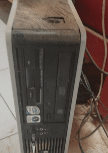
- CNC Setup: Load the saved toolpath file into your CNC machine's control software, in this case is "AR2400"
- Set Origin: Establish the workpiece origin (zero point) on the CNC machine.
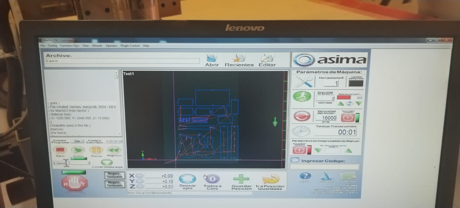
- In this case, to move along the X, Y, and Z axes, you use the arrow keys on the keyboard. However, simultaneously, you need to hold down the Shift key.
- For manipulating the Z-axis, you use Shift + Page Up to move upwards and Shift + Page Down to move downwards.
- For the speed, it is important to mention that I colocated:
- Execute Toolpaths: Run the CNC machine to execute the programmed toolpaths and cut your design into the material.
- Inspect Finished Parts: Once machining is complete, inspect the cut parts for accuracy and quality.
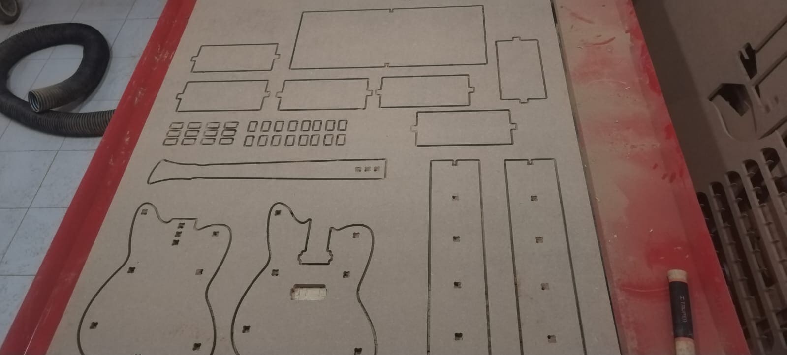

- Assembly everything:
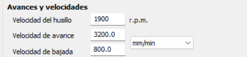
It is important to mention that it actually was really slow and it took almost the double to cut, that it would take at higher speed; but it is important to mention it actually cut it really good.
Don't make the same mistakes as me...
| Mistake | Solution |
|---|---|
| One of the problems I faced was trying to install T-bones onto the tabs of my organizer. However, when I attempted to assemble them, they didn't fit entirely. | To resolve this issue, I decided to sand them down. By doing so, I adjusted their size and shape, enabling the tabs to fit snugly and correctly when assembled. |
| One mistake I made was not properly leveling the Z-axis. I mistakenly leveled it in the area that wasn't bowed, causing the tool not to pass through entirely. | I solved this by simply leveling the Z-axis in the bowed area, allowing it to pass through correctly. |
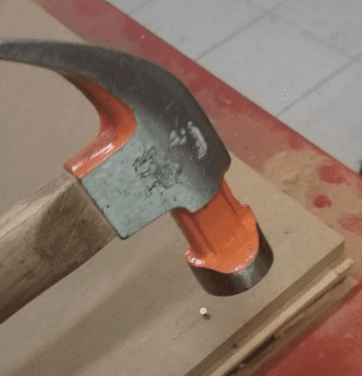
| This wasn't exactly an error, but when I was unscrewing the screws from the table and bed of the CNC, I accidentally injured myself while using a hammer to remove a stubborn screw. | Therefore, the solution for next time is to wear gloves for protection to avoid any injuries. |
Results
Documents
- ZIP of the solidworks documents and dxf of the guitar.
- ZIP of the solidworks documents and dxf of the organizer.
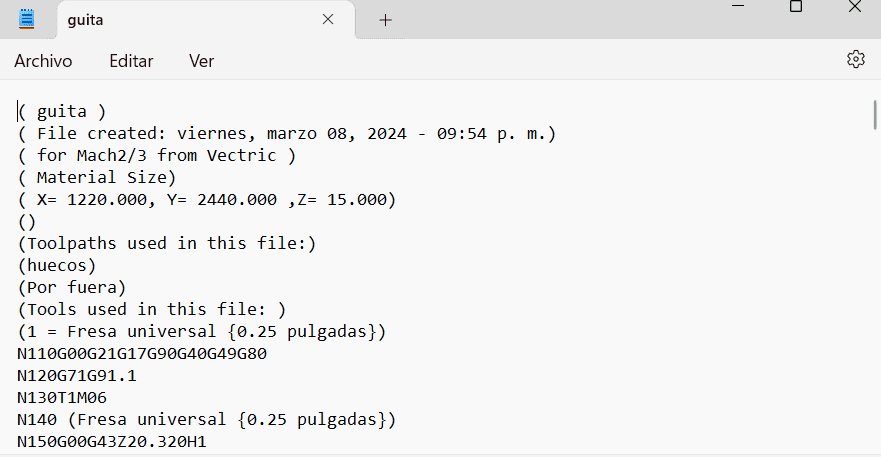
- Gcode of the guitar and the organizer.