Networking and communications
Here its our group assigment: Week 13Types of communications:
There are different protocols of communications, for example: UART, SPI and I2C protocols.
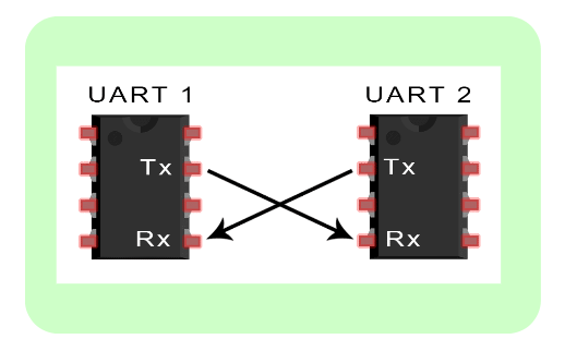
UART- UART is a simple asynchronous serial communication protocol used for transmitting and receiving data between two devices. It consists of two wires: one for transmitting data (TX) and one for receiving data (RX).
- Communication in UART is asynchronous, meaning that there is no separate clock signal shared between the devices. Instead, both devices must agree on a common baud rate (bits per second) for data transmission.
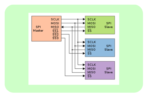
- SPI is a synchronous serial communication protocol commonly used for short-distance communication between microcontrollers and peripheral devices.
- SPI uses four wires: MOSI (Master Out Slave In), MISO (Master In Slave Out), SCK (Serial Clock), and SS/CS (Slave Select/Chip Select).
- SPI typically operates in a master-slave configuration, where the master device initiates communication with one or more slave devices.
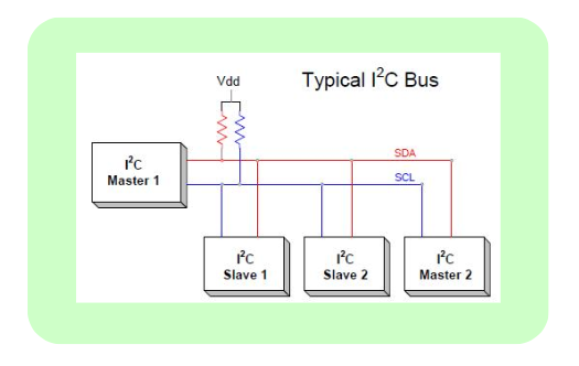
- I2C is a multi-master, multi-slave serial communication protocol commonly used for communication between integrated circuits on a circuit board.
- I2C uses two wires: SDA (Serial Data Line) and SCL (Serial Clock Line).
- Unlike SPI, which typically uses separate slave select lines for each device, I2C uses a unique address assigned to each slave device on the bus.
Before starting...
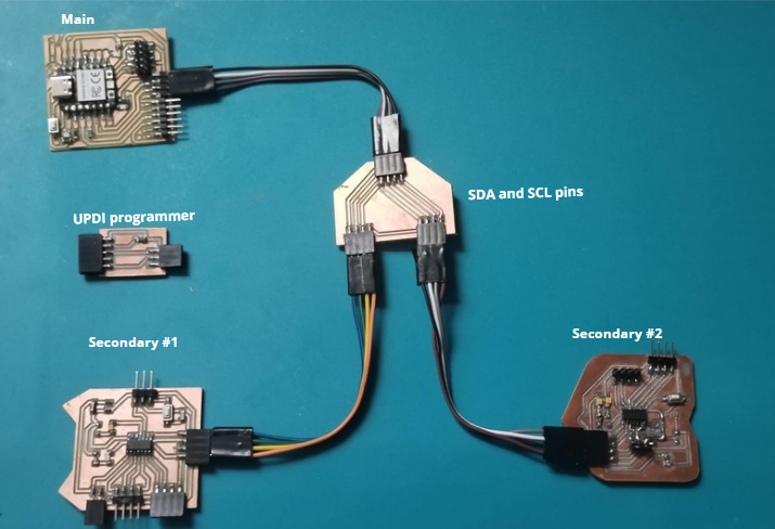
As I was going to use I2C, the board I was going to use as the master didn't had enough pins for SDA and SCL, that why I designed a small board only for adding more pins. So here it is the process:
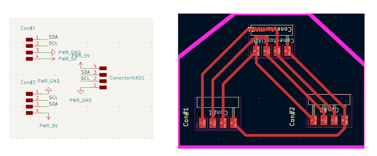
Board schematic and design done in KiCad, following the same steps that my other board in other weeks.
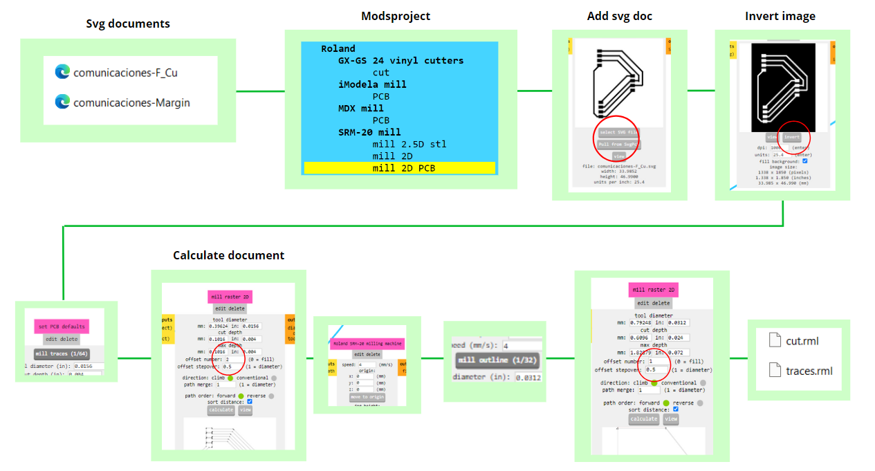
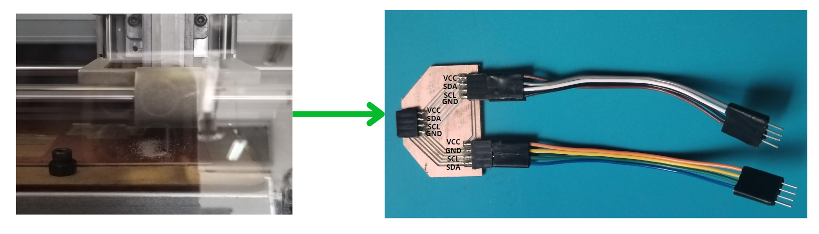
Final result of the the board, I only solded some pins, so that the jumpers could enter perfectly.
Documents of the board
Let's start :0
Now that I had my connecting board, I decided to use the following boards I had made for other assigments:
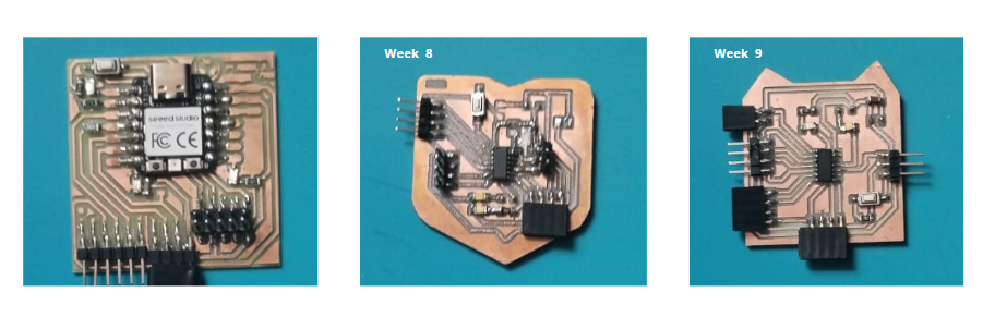
Board of the Week 9
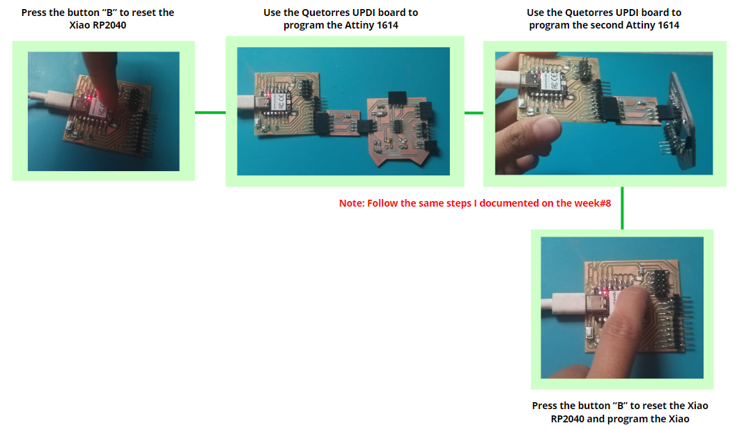
It is important to mention that as each of the boards need to be programmed individually, so here it is the process I followed to program each of them:
Everytime I programmed, to check everything I had to connect everything like this:
Program #1 LED:
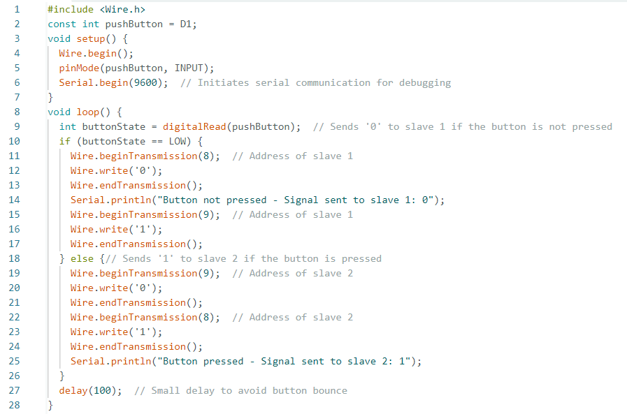
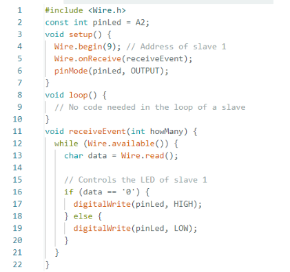
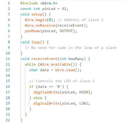
The three codes implement data communication using the I2C protocol between a main device and one or multiple secondary devices. In the first code, the main device sends signals to two secondary devices depending on the state of a button; one secondary receives '0' when the button is not pressed, and the other receives '1' when the button is pressed. The second code represents a secondary device that receives signals from the main and controls an LED based on the received data; if it receives '0', it turns on the LED, otherwise, it turns it off. Lastly, the third code is similar to the second but for a different secondary device; it also controls an LED in response to signals from the main, but this device has a different address and an LED on a different pin.
Program #2 Motor and Led:
The three codes implement data communication using the I2C protocol between a main device and one or multiple secondary devices. In the first code, the main device sends signals to two secondary devices depending on the state of a button; one secondary receives '0' when the button is not pressed, and the other receives '1' when the button is pressed. The second code represents a secondary device that receives signals from the main and controls an LED and motor based on the received data; if it receives '0', it turns on the LED, otherwise, it turns it off. Lastly, the third code is similar to the second but for a different secondary device; it also controls an LED in response to signals from the main, but this device has a different address and an LED on a different pin.

Mistakes and how I solve them
| Problem | How we solve it | One of the primary obstacles I encountered early on stemmed from the constraint of not possessing a board that boasted an ample number of pins specifically designated for the Serial Data (SDA) and Serial Clock (SCL) lines. This deficiency arose primarily due to the nature of the pre-existing practice boards I had at my disposal. These practice boards, being primarily intended for introductory exercises and rudimentary experiments, were not originally engineered with the extensive pin configurations required for more advanced projects. | This bottleneck prompted me to devise an additional board to facilitate the connection between the two existing boards. While this solution demanded the creation of a new board design and implementation, I found the process surprisingly expedient. |
|---|---|
| However, as the project progressed, a more nuanced challenge emerged, stemming from the utilization of two distinct types of microcontrollers. This divergence led to a significant time investment during the programming phase. Any minor missteps in programming necessitated a complete reset of my Xiao board to accommodate the programming of the ATtiny microcontroller, followed by a switch back to the original configuration. | In hindsight, it's evident that employing microcontrollers from the same family could have mitigated this issue, streamlining the programming process and ultimately reducing time expenditure. |