Molding and casting
Here its our group assigment: Week 12Group assigment
- Review the safety data sheets for each of your molding and casting materials.
Here are some of the safety points I recovered from this link:
- It is NOT a hazardous substance or mixture according to United States Occupational Safety and Health Administration (OSHA)
- In case of eye contact, flush eyes with plenty of water
- In case of skin contact, wash thoroughly with soap and water.
- Prevent spilled material from entering sewers, storm drains or unauthorized drainage systems and natural waterways by using sand, earth, or other appropriate barriers.
- Use good general housekeeping procedures. Wash hands after use. Do not get in eyes, on skin or on clothing. Do not breathe vapors or mists.
- Respiratory protection is not normally required when using this product in open environments with adequate ventilation
- Wear any liquid-tight gloves such as butyl rubber, neoprene or PVC.
- Never eat, drink, or smoke in work areas.
Individual assigment
- Design a mold around the process you’ll be using, produce it with a smooth surface finish, and use it to cast parts.
Design
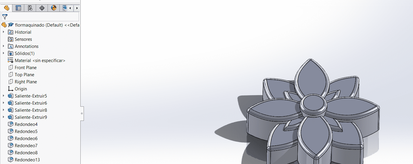
Personally I wanted to do a flower mold for doing candles and maybe trying to sell them.
Here are the steps I followed:
-
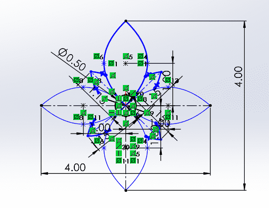
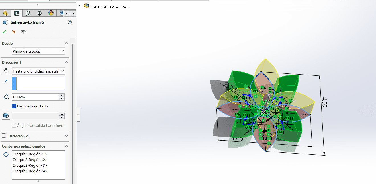
The main idea it is that I designed 3 main parts that were extruded in different sizes, so that the mold had different heights.
-
This first part was extruded 1cm tall, based on the design I planned before.
-
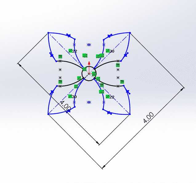
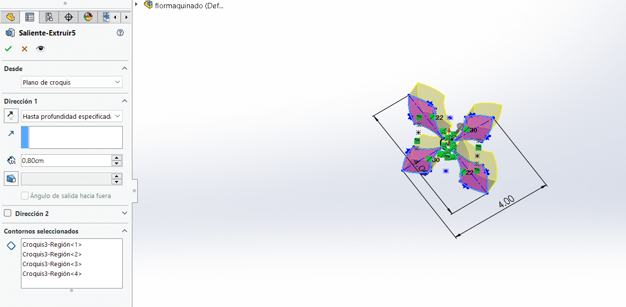
I drew the other four petals of the flowers that it is clearly going to be extruded in a different height, the main purpose it is to create the effect of different points of starting.
-
This part was extruded 0.8 cm, a little bit smaller than the other parts.
-
Now the last part I drew was a circle that was going to be the stigma.
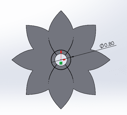
-
This was extruded 1.20 cm.

-
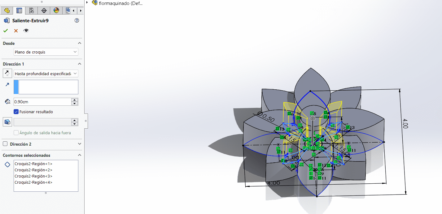
I draw some small 4 petals of the rose so it can have more decoration.
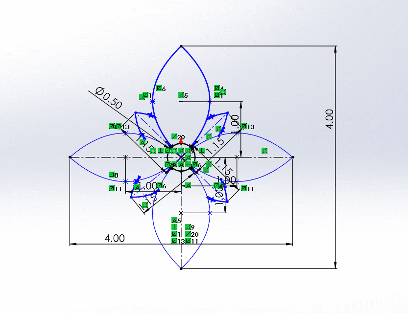
-
This was extruded 0.9 cm.
-
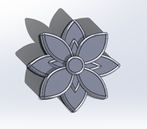
-
Then I rounded 0.1cm the borders of all the flower.
-
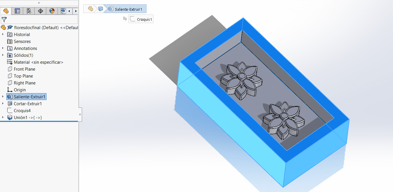
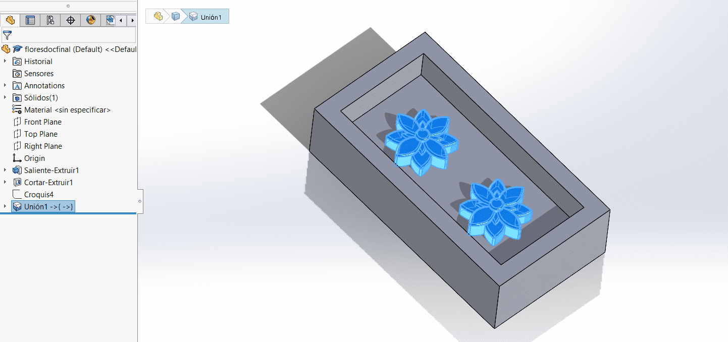
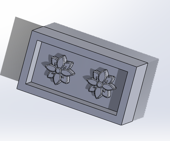
Then I did an assembly of the wax block (15x80x40cm) so
-
For this week the idea was to use the sensors I am goint to use for my final project, in this case the following ones:
-
Vcarve
Here are the steps for doing the document in Vcarve for the CNC machine:
-
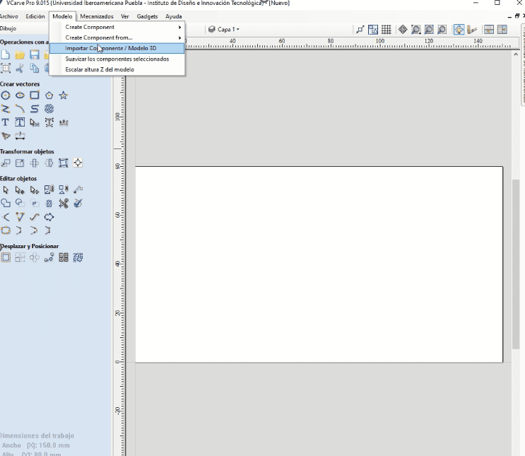
Open VCarve and create a new file/project.
Import the STL file by going to "File" > "Import" > "Import Component or 3D Model" and select your STL file.
-
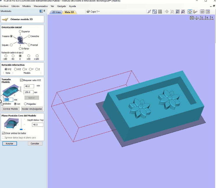
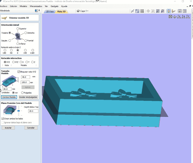
Define your material size and thickness in the "Job Setup" window.
Make sure it matches the actual size and thickness of the material you'll be working with.
-
Set your X, Y, and Z zero reference point. This is usually the lower left corner of your material surface.
Use the "Set XYZ Zero" button in the "Job Setup" window to establish this point.
-
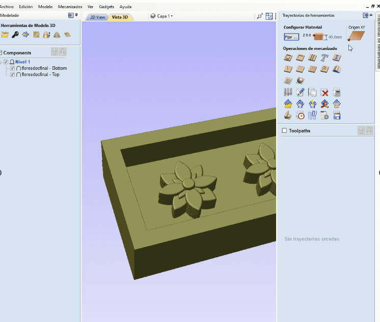
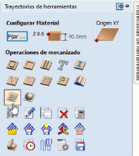
Go to the Toolpaths tab.
Click "Create a new toolpath" and select "3D Roughing".
-
Choose a suitable tool (like an end mill) for roughing.
Set a boundary around your model if needed.
Calculate the toolpath.
Review the toolpath simulation to ensure it looks correct.
Save the toolpath with a descriptive name.
-
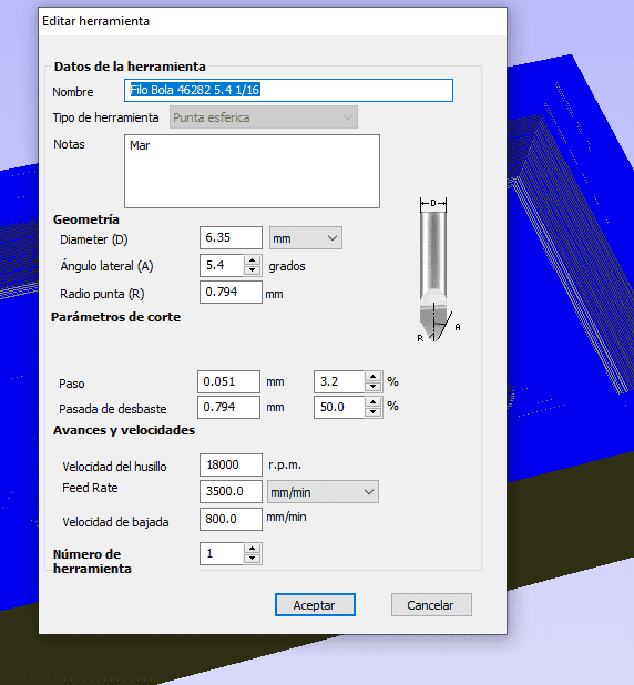
Here are the proper parameters to create the document:
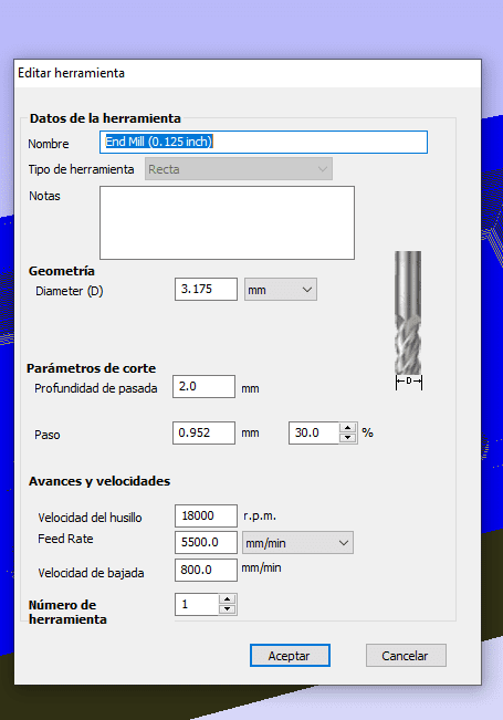
-
In this option you can properly see the simulation of what it is going to do:
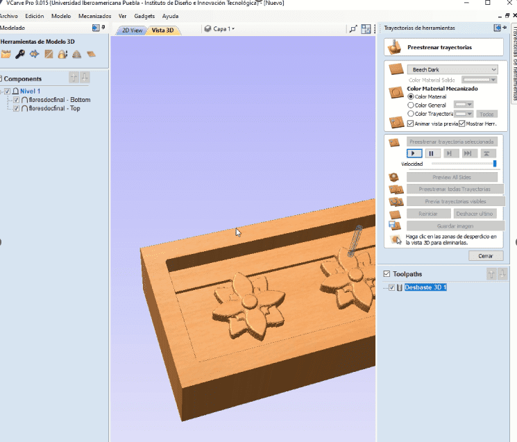
Desbasting
-
Create a new toolpath again, this time selecting "3D Finishing".
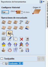
- Choose a smaller, finer tool (like a ball nose end mill) for finishing.
-
Here are the proper parameters to create the document:
- Save all the proper documents, on the correct processor:
Finishing
CNC machining
-
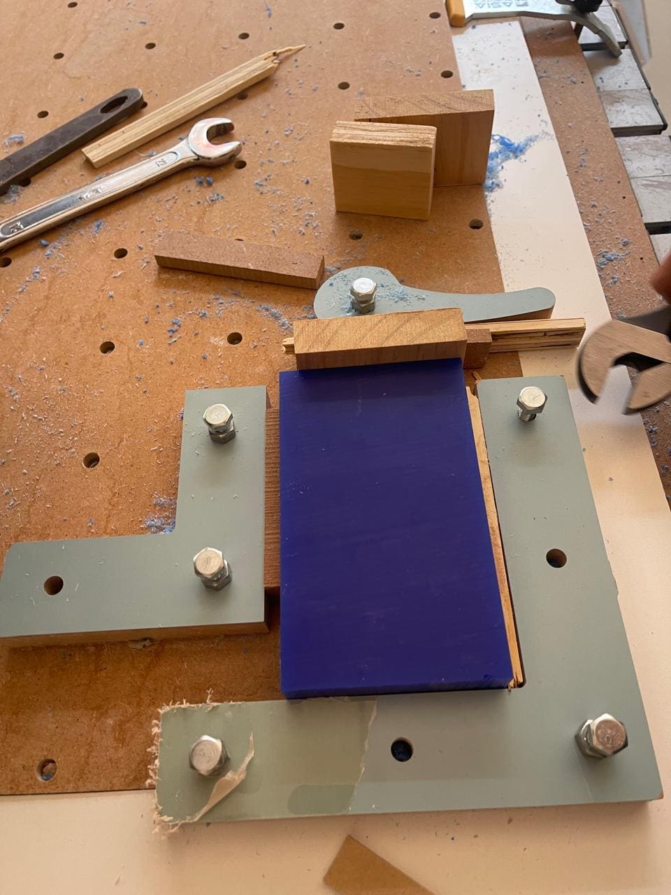
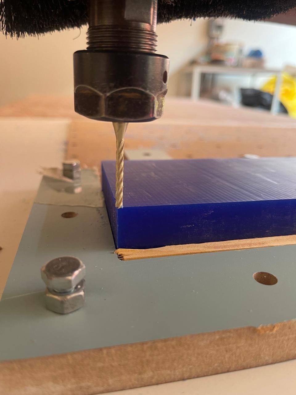
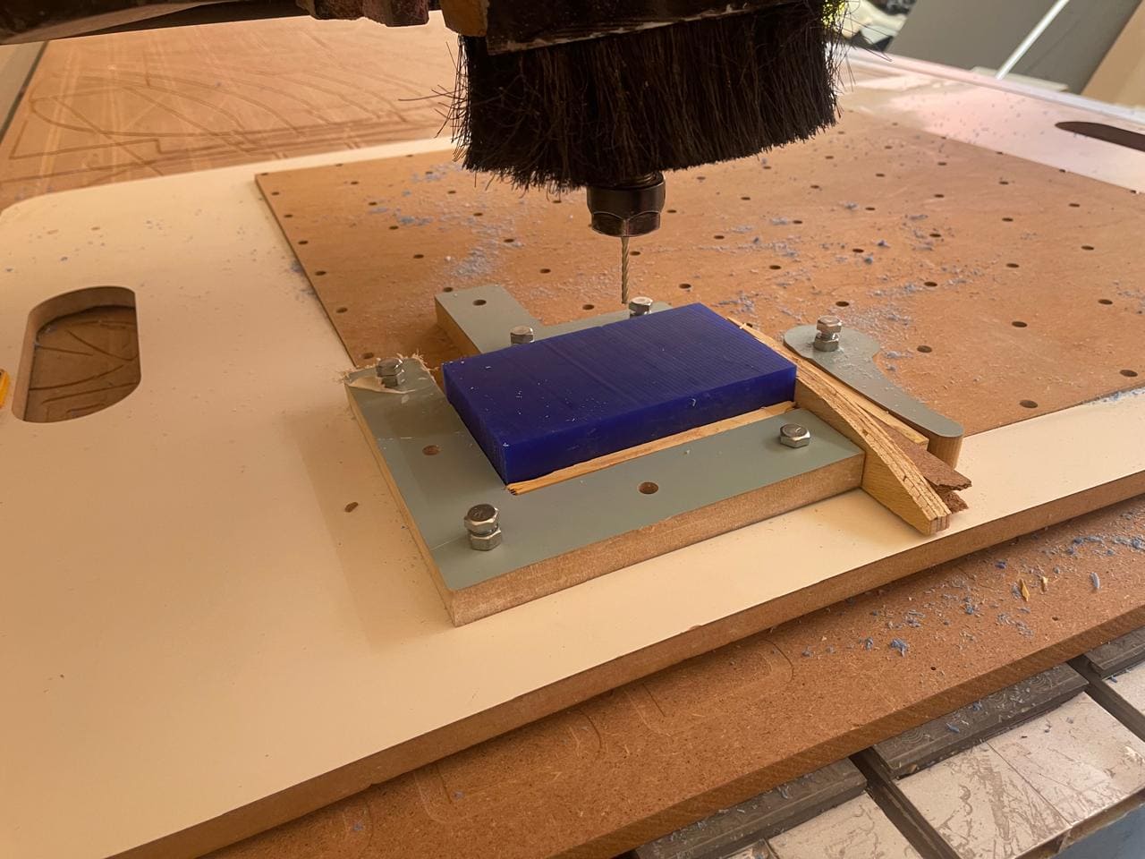
Before starting any CNC work, it's crucial to securely clamp down the material. In this case, wax is being used. The wax should be placed within the designated work area on the machine's bed. Tightening the nuts ensures that the wax is firmly held in place, preventing any movement during machining. This step is essential for accurate and safe machining.
-
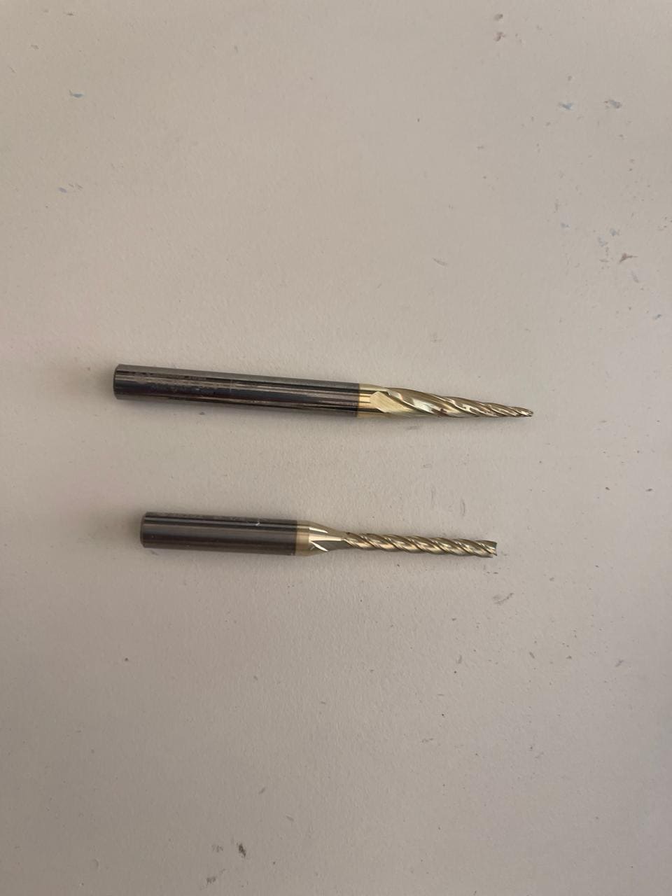
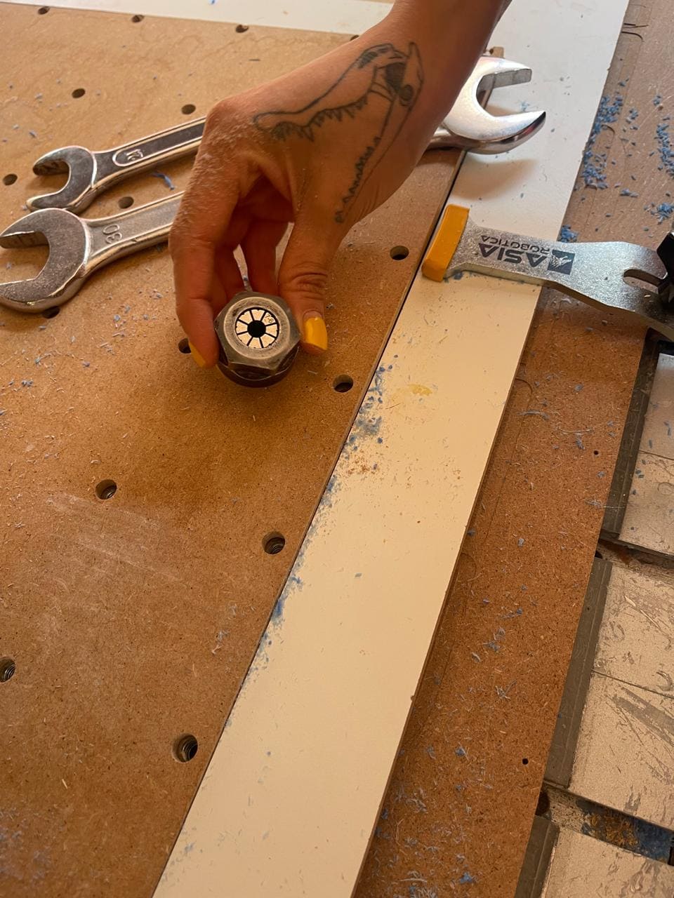
The two tools used are:
Amana Tools 1/16" Ball Nose Tool: This tool is likely used for detailed work or finishing passes. The ball nose design allows for smooth contouring and intricate designs.
Amana Tools 46292 1/8" Tool: This tool is a larger end mill, likely used for roughing or removing bulk material. The 1/8" size indicates it can remove material faster than the 1/16" tool.
-
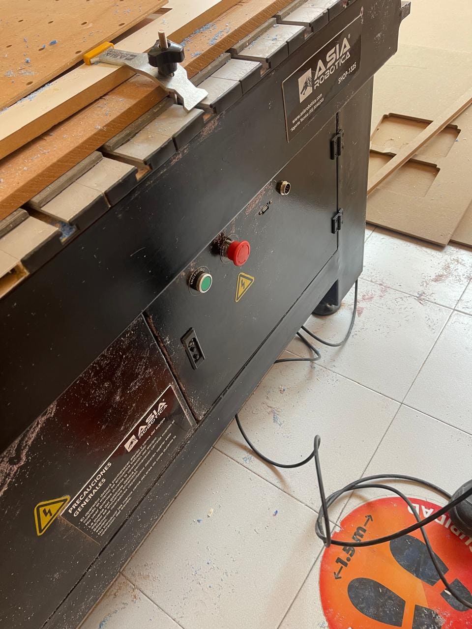
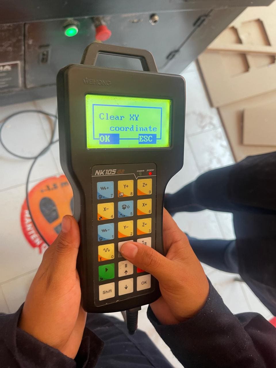
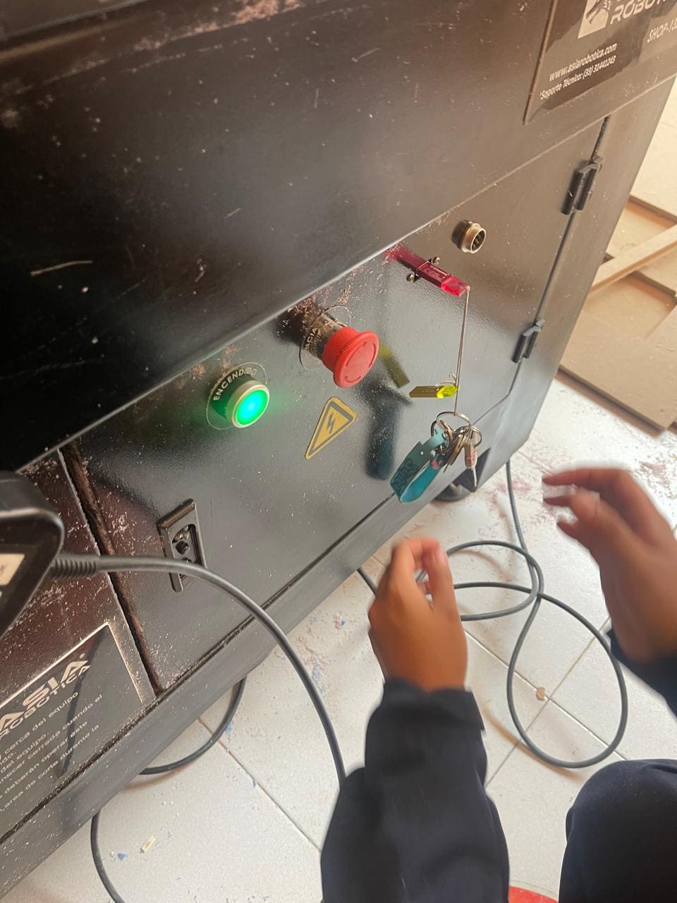
To power up the CNC machine, the green button is pressed. This initiates the startup process of the machine. The removal of the safety button is a standard safety measure to prevent accidental activation.
-
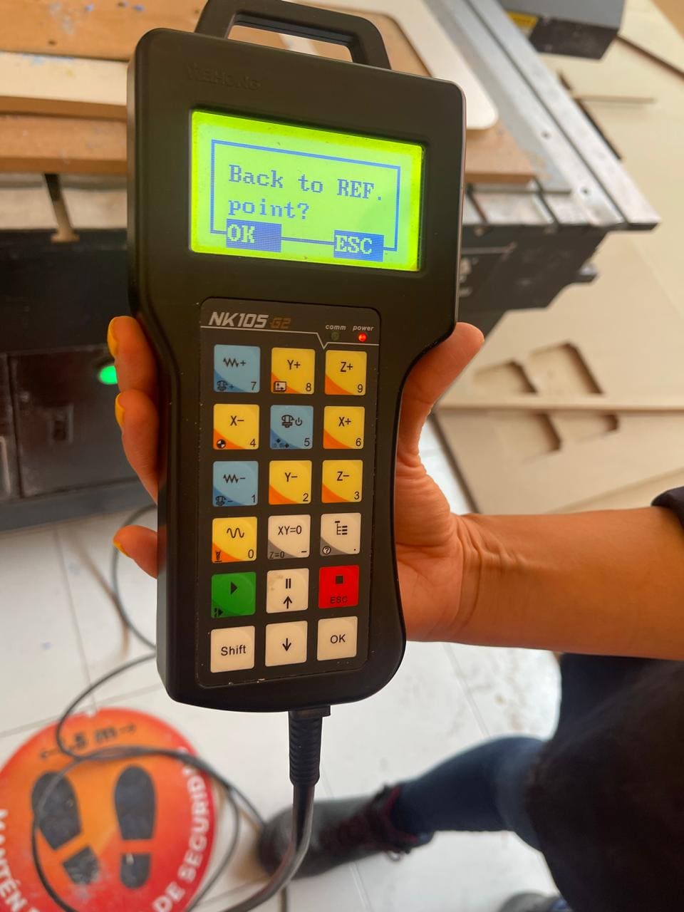
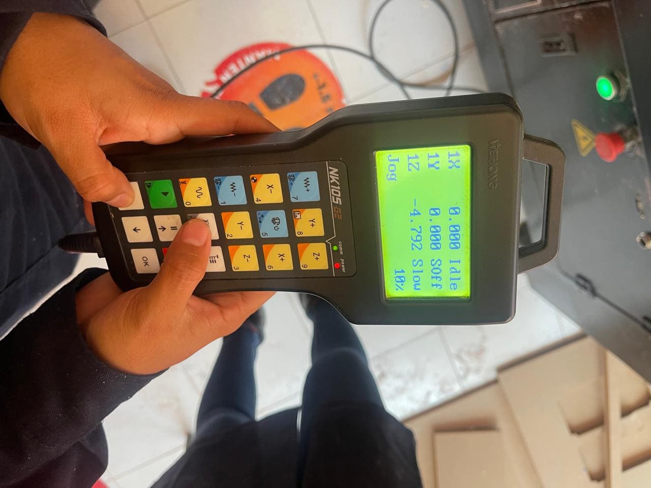
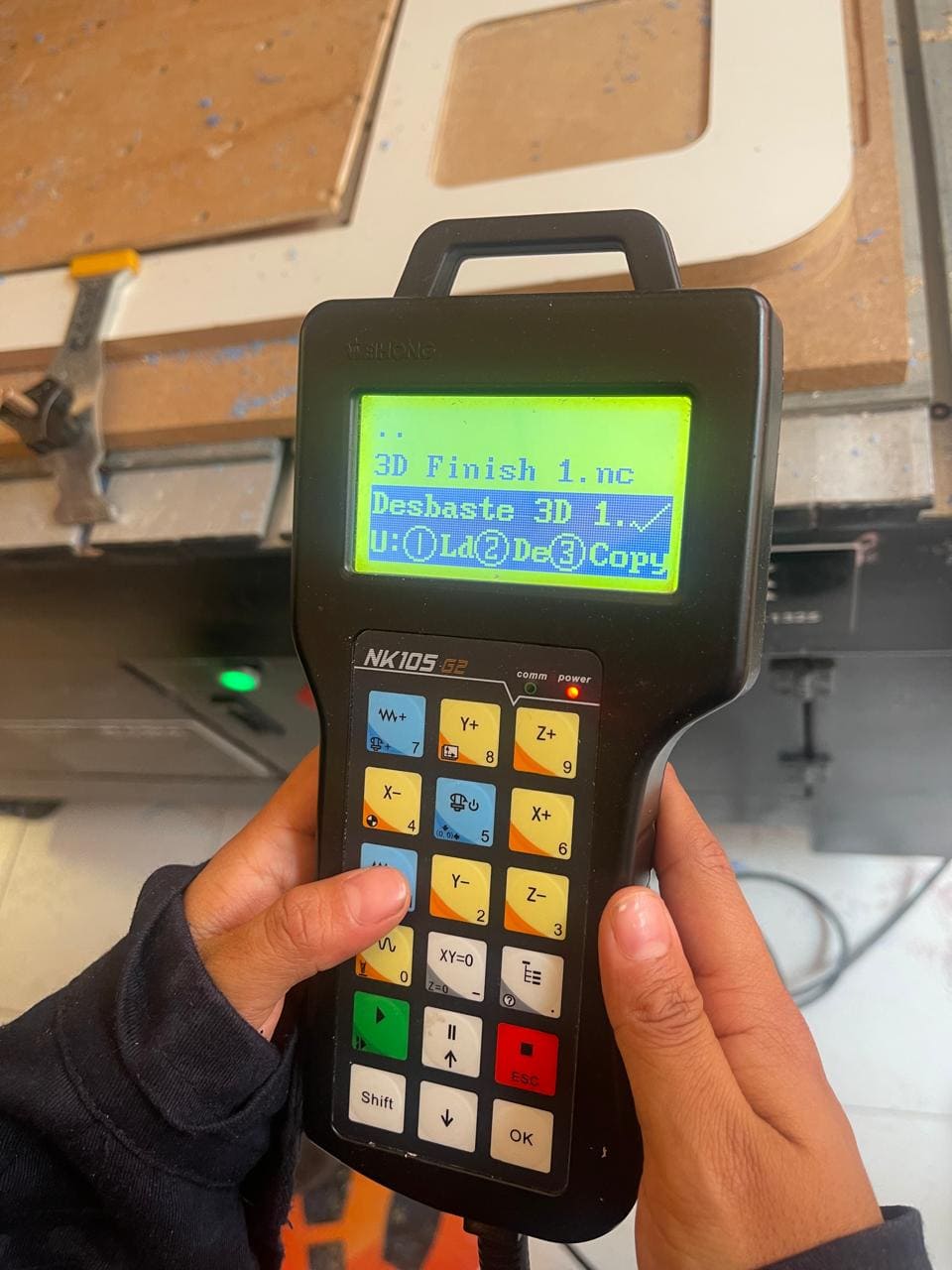
The image provided shows the control panel of the CNC machine. This control panel allows the operator to move the machine's axis. When the machine is turned on, it prompts the operator to send it to a reference point. This reference point is crucial for establishing the machine's starting position.
-
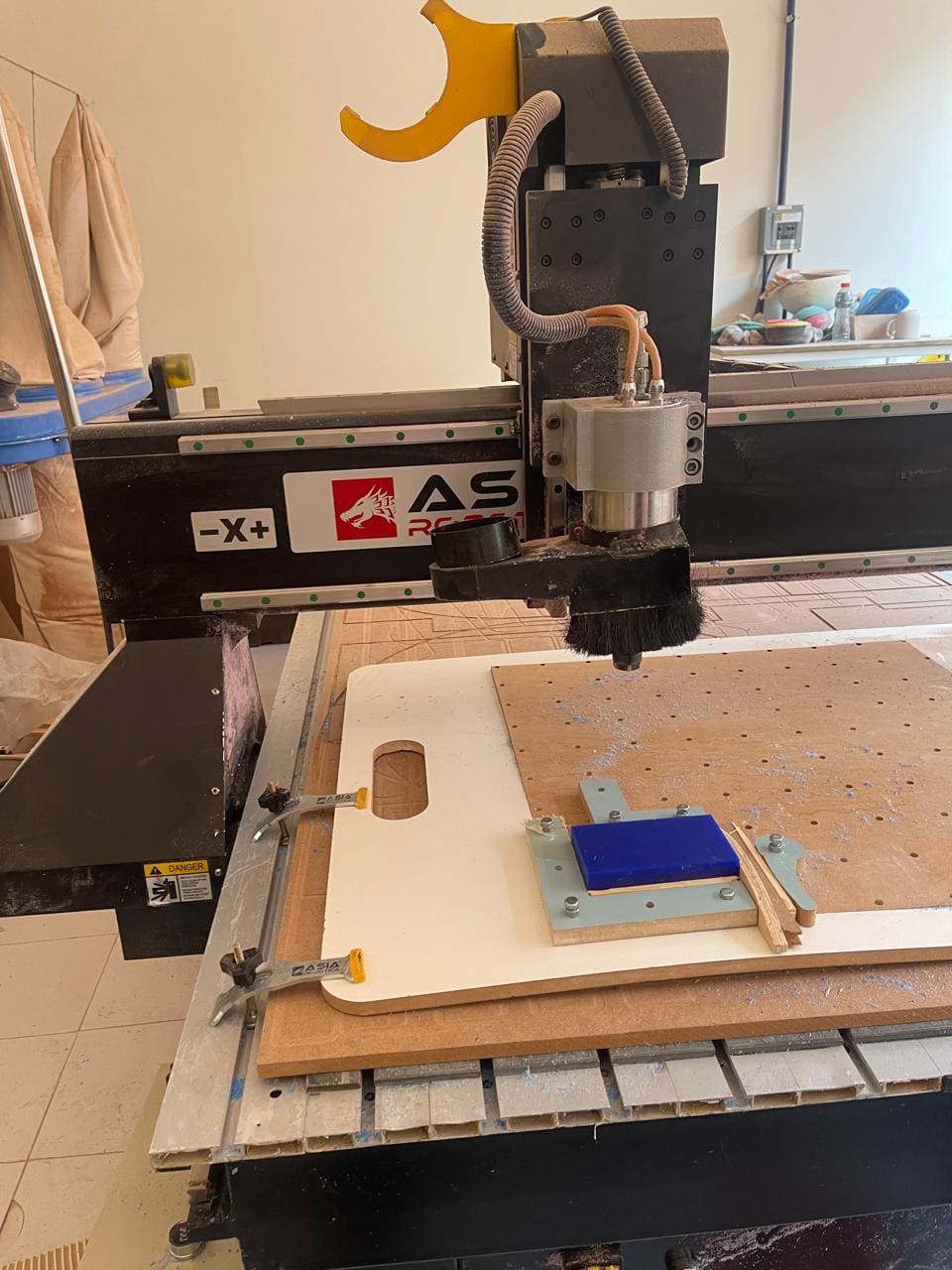
This image illustrates how the setup should look once the material (wax) and tools are correctly placed. It ensures that everything is in its designated position before proceeding with machining operations.
-
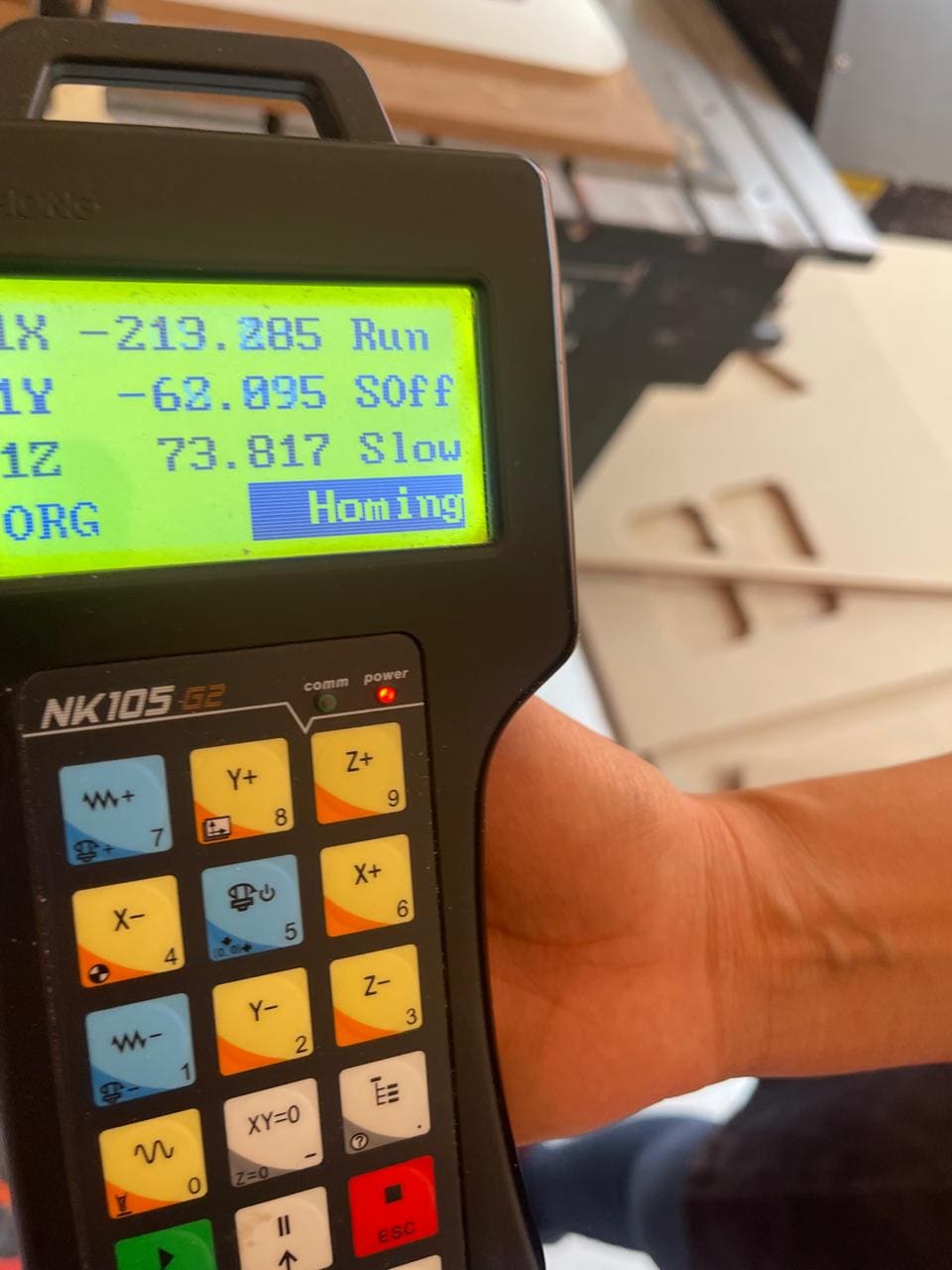
Homing the machine is a standard procedure in CNC machining. It involves the machine moving to a predefined home position to establish its starting reference point. This ensures accuracy and consistency in machining operations.
-
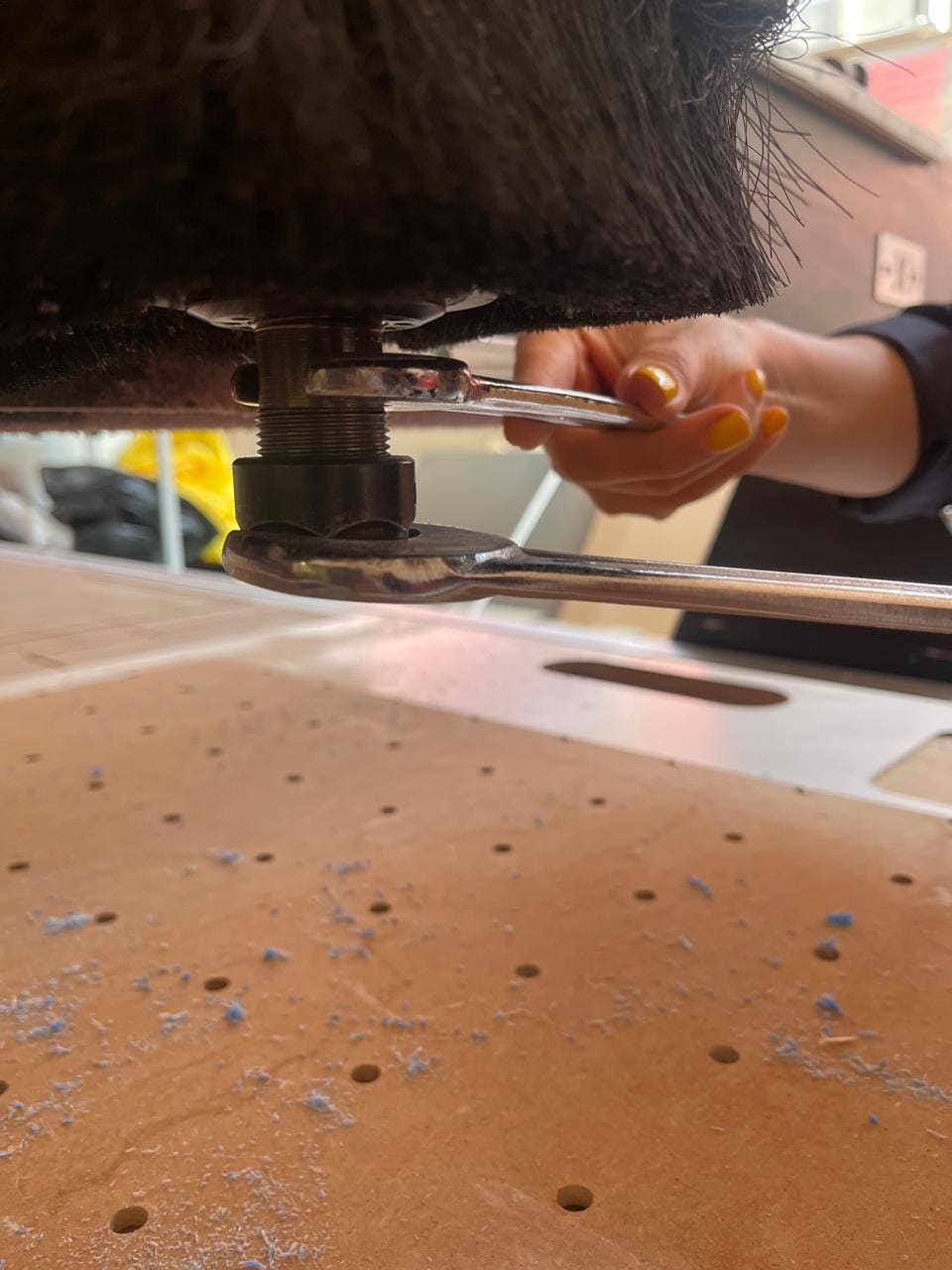
The tool holder is the part of the machine where the cutting tool is inserted and secured. Tightening it ensures that the tool is held firmly in place during operation. The comparison to "turning like a scissor" indicates that it should be tightened securely, similar to how one would tighten a scissor handle.
-
The sponge placed in the tool holder serves as a safety precaution. If the cutting tool were to fall out of the holder, the sponge would cushion its fall, preventing potential damage or injury. It's a simple yet effective way to protect both the tool and the machine.
-
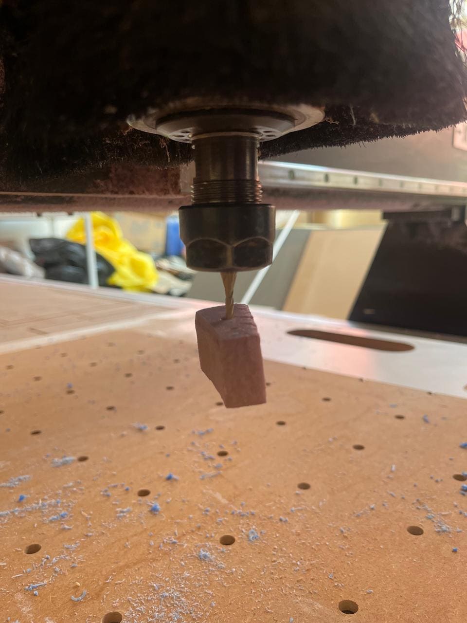
This step emphasizes the correct orientation of the tool when inserting it into the tool holder. The tool should be positioned so that half of it is inside the tool holder and the other half is outside. This ensures that the tool is properly secured and aligned for machining operations.
-
Pressing the specified key on the control panel sets the X-axis. This action establishes the X-axis as the reference axis for the machine's movements. Setting the axis correctly is crucial for accurate machining along the X-axis.
-
Pressing the two keys indicated on the control panel sets the Z-axis. Similar to setting the X-axis, this action establishes the Z-axis as the reference axis for vertical movements. Properly setting the Z-axis is essential for accurate depth control during machining.
-
The image shows the completed setup with the tool inserted, oriented correctly, and secured in the tool holder. This final check ensures that everything is in place before proceeding with machining operations.
-
Connecting the USB allows for transferring the machining code (G-code) from a computer to the CNC machine. This step is crucial for loading the instructions that the machine will follow for the specific machining operation.
-
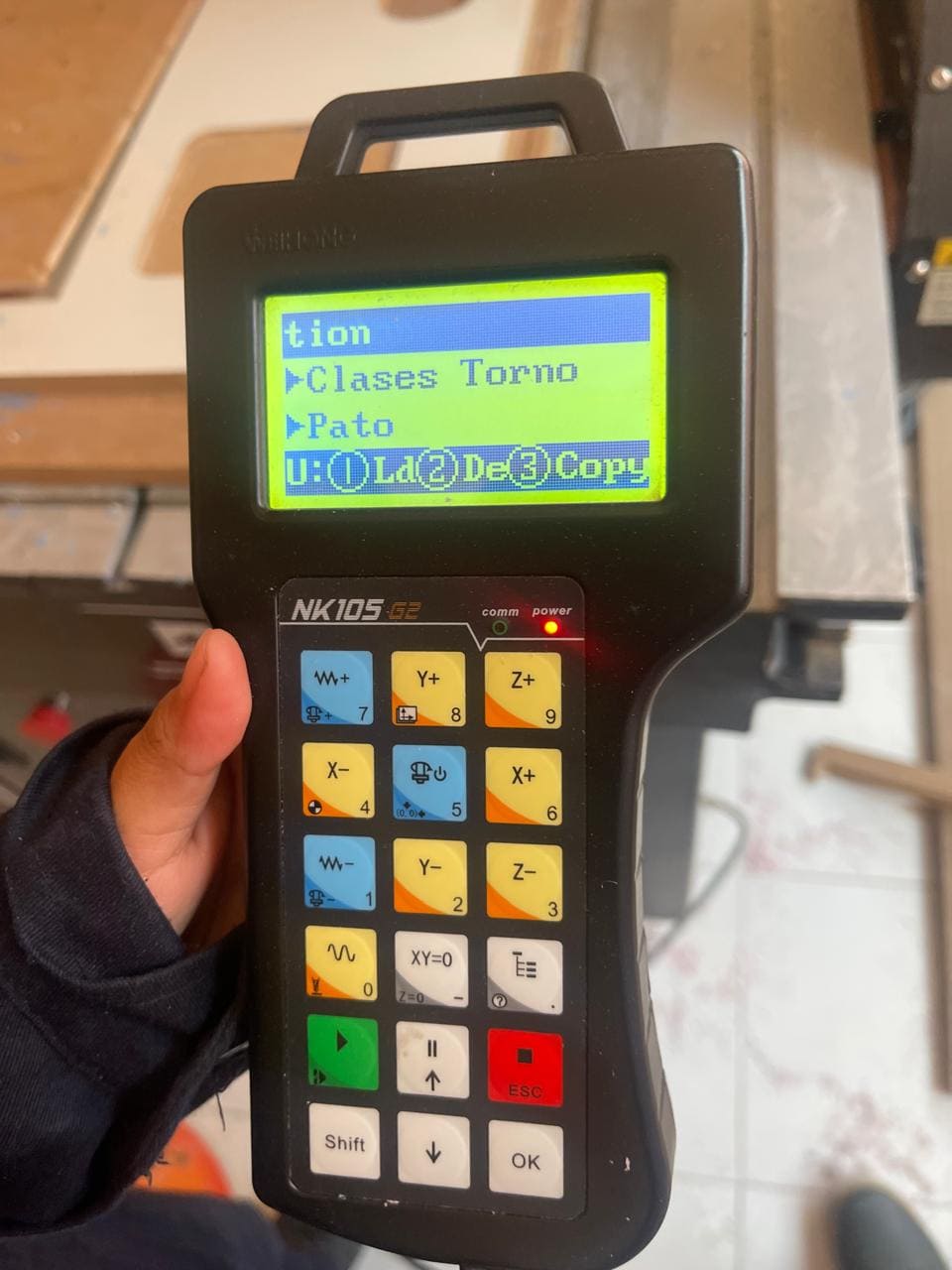
Once the USB is connected, the operator navigates through the machine's interface to locate and open the desired machining file. This file contains the instructions (G-code) for the specific design or part to be machined.

-
After selecting the file, the operator uploads the G-code to the machine by pressing the specified key. This action transfers the machining instructions from the file to the CNC machine's control system. Once uploaded, the machine is ready to execute the programmed machining operations.
Desbasting video
Finishing video
Silicon mold
The process began by creating a silicon mold using a wax mold. This wax mold serves as a pattern for the final silicon mold.
- The silicon material is typically a two-part compound, often referred to as Part A and Part B. In this case, the ratio used was 100 parts A to 10 parts B. This ratio is crucial for the silicon to cure properly and achieve the desired properties.

- To determine the amount of silicon needed, the volume of water in the wax mold was measured. The total volume of water came out to be 117 milliliters.
-
With the 100:10 ratio in mind, the calculation for the specific amounts of Part A and Part B was straightforward. For Part A, which is 100 times larger than Part B, 117 ml of water translated to 117 ml of Part A. For Part B, which is 10 times smaller than Part A, 117 ml of water equated to 11.7 ml of Part B.

-
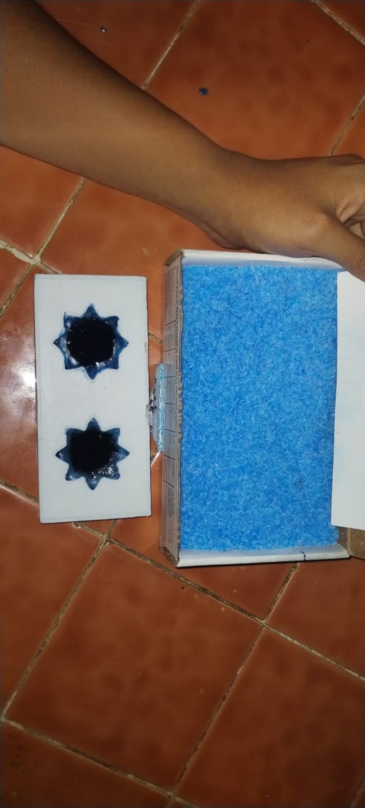
The mixed silicon was then carefully poured into the wax mold. It's essential to pour slowly and steadily to avoid air bubbles, which can create imperfections in the final mold.
- After pouring the silicon into the mold, it was left undisturbed for 12 hours. This waiting period allows the silicon to cure and set properly.
-
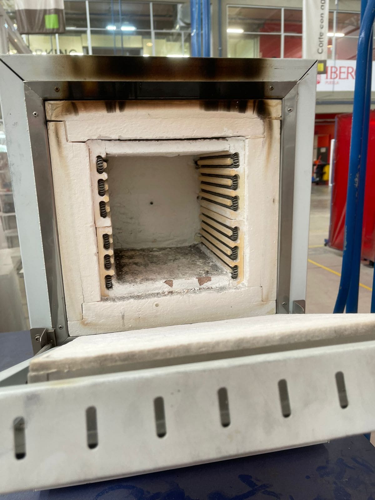
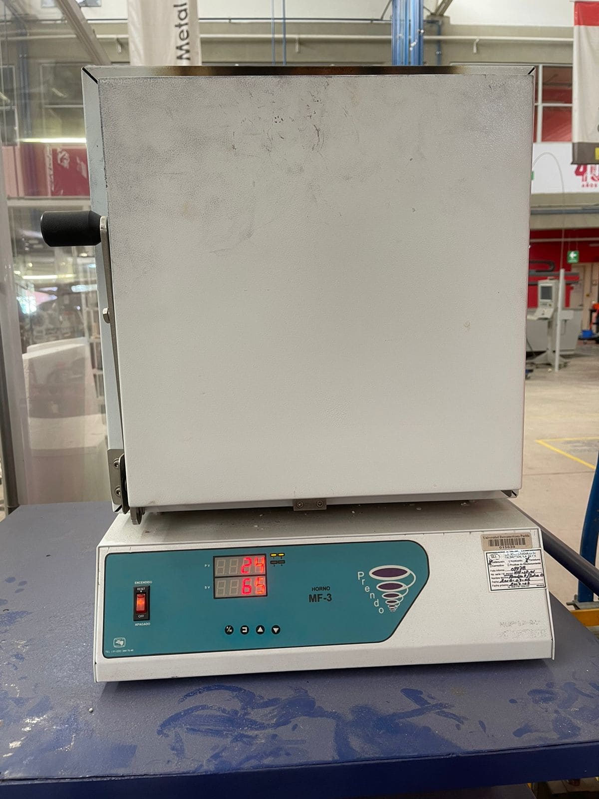
To further enhance the curing process and ensure the silicon reaches its full strength and stability, the mold was placed in an oven set to 65°C (149°F). This temperature is typically recommended for curing silicon molds and may vary depending on the specific type of silicon used.
-
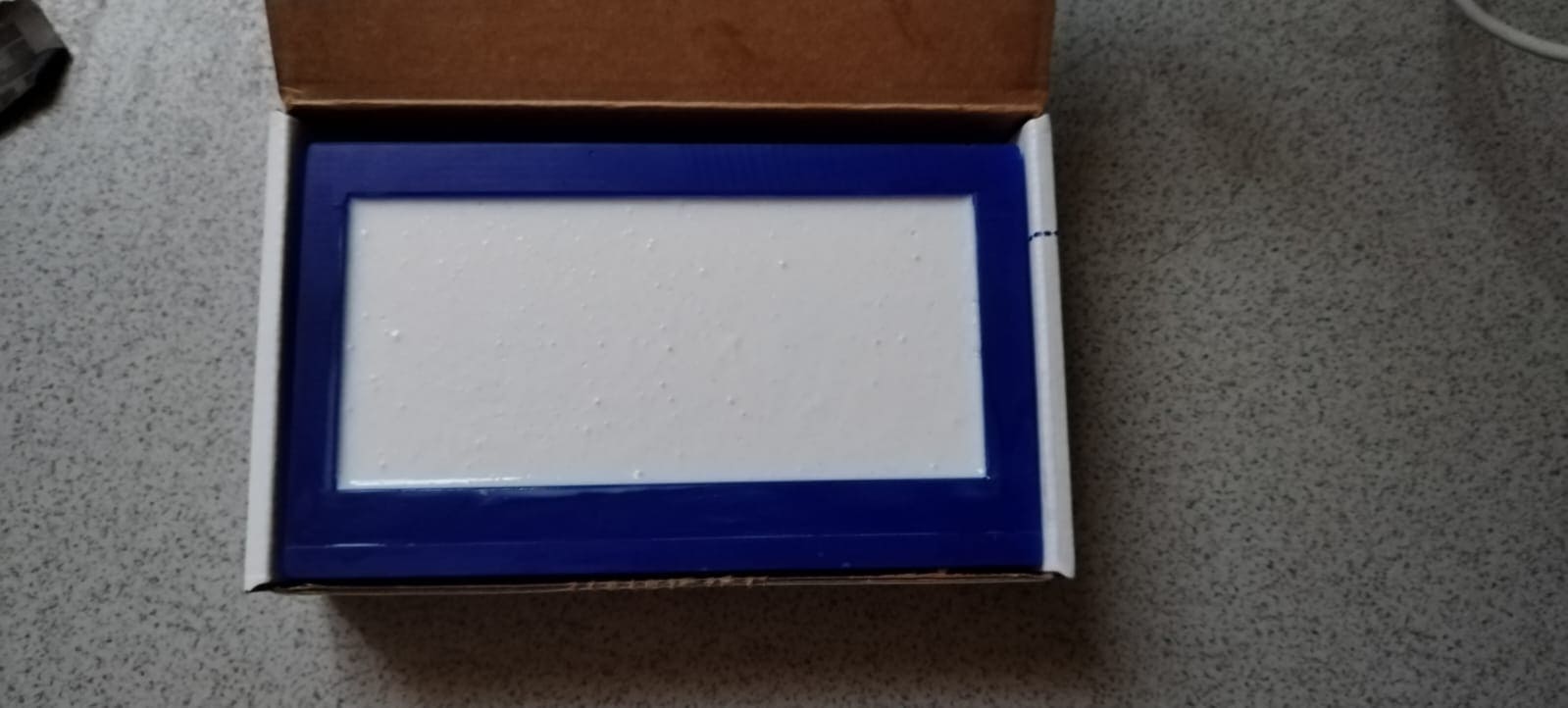
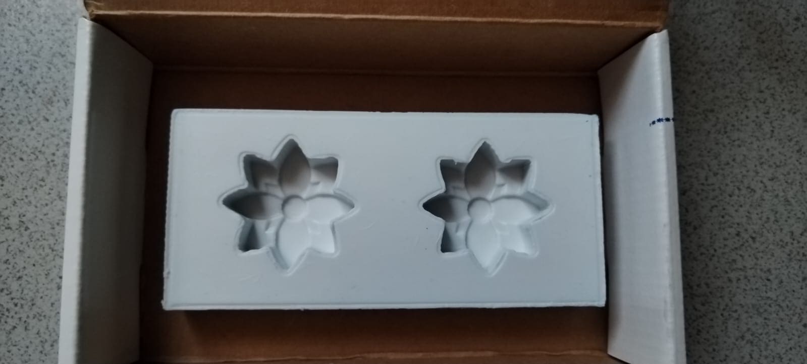
After the curing process was complete, the silicon mold was allowed to cool to room temperature. Once cooled, the silicon mold was carefully removed from the wax mold. The result is a durable and precise silicon mold ready for its intended use, such as casting resin, soap, or other materials.
Molding
As you can see in the begining after reading the datasheet, I did the molding.
-
The process began by melting the leftover wax from making the wax mold. This wax would be reused to create candles.
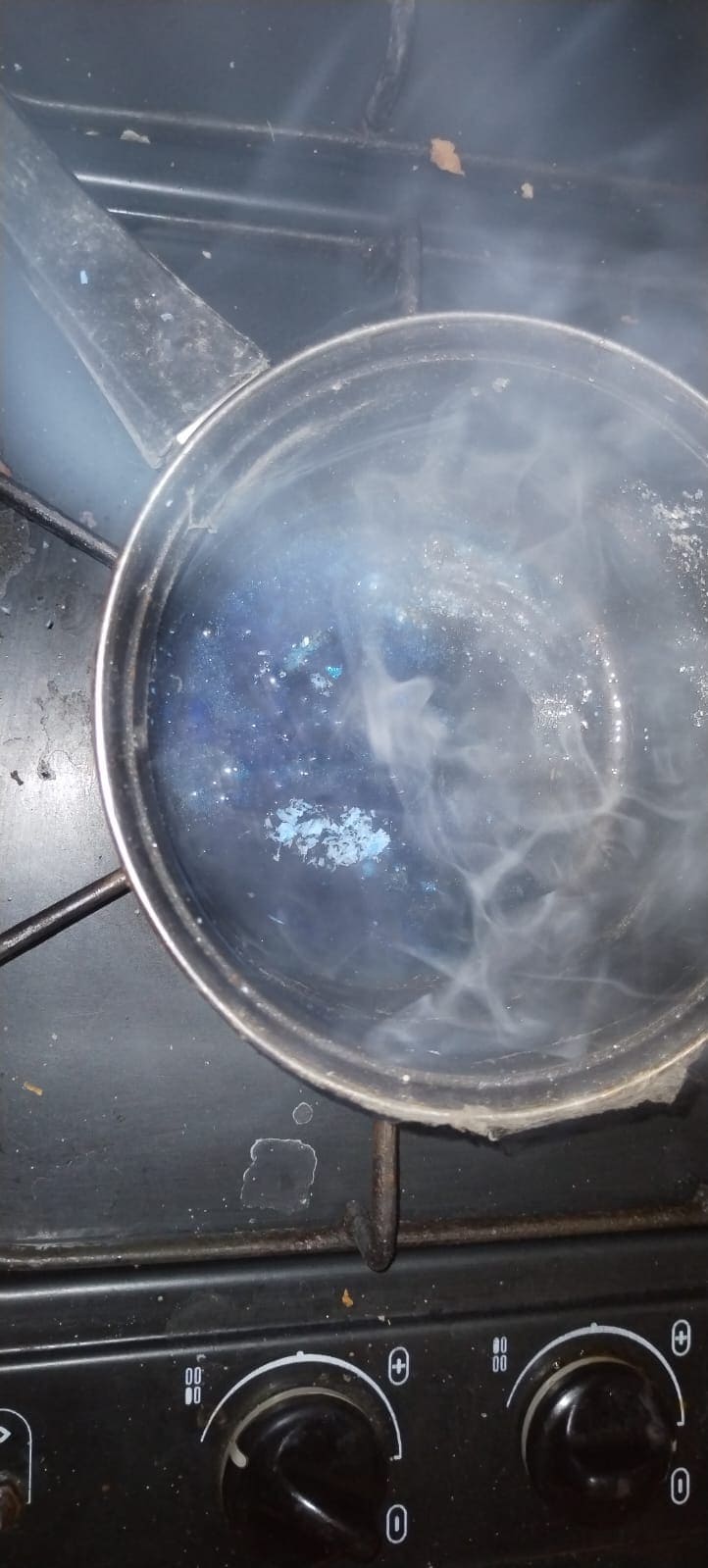
- Once the wax was melted, it was carefully poured into the silicone mold. This mold was created earlier for making candles.
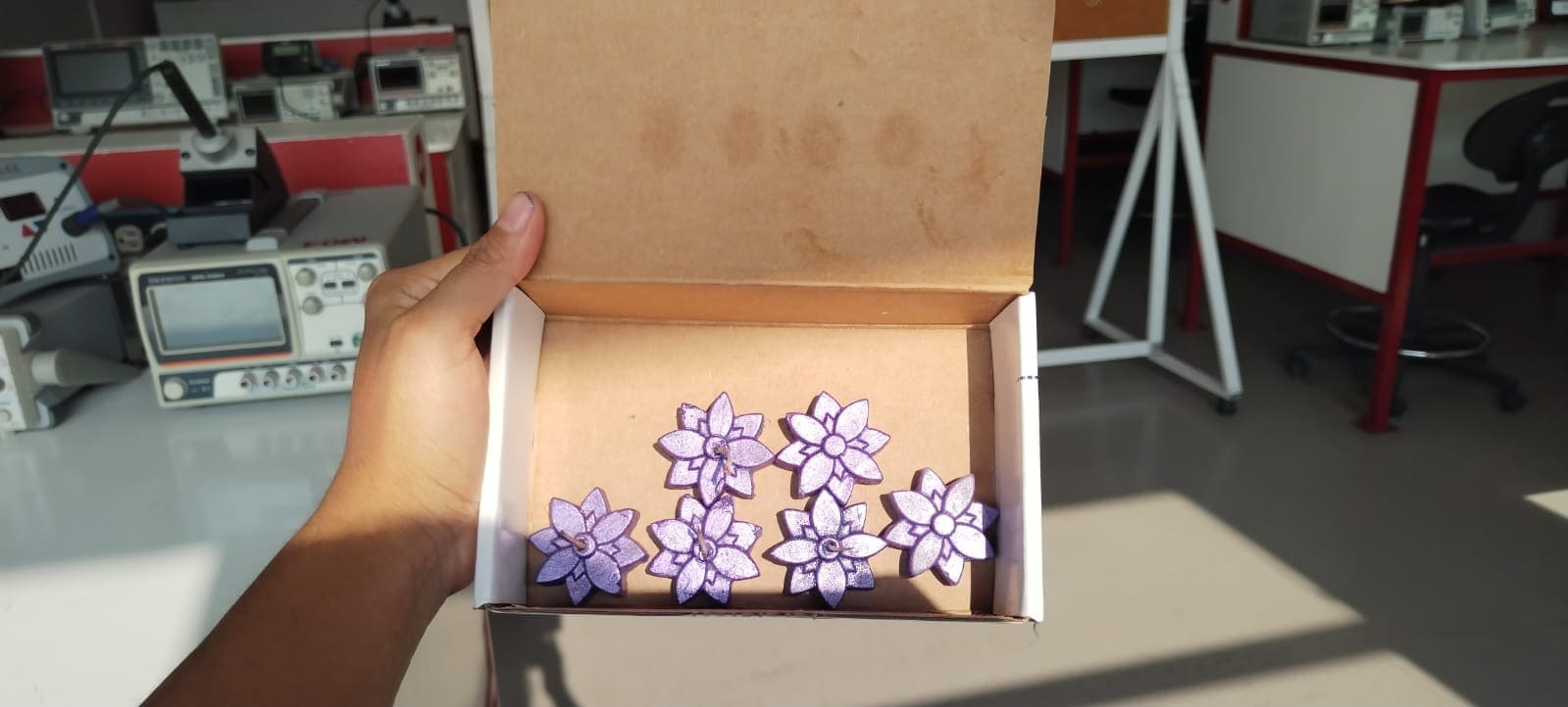
- After pouring the melted wax into the silicone mold, it was left to cool and solidify. This cooling process typically took about 30 minutes to ensure the wax hardened properly within the mold
- With the wick in place, any final adjustments or trimming of the wick, referred to as "litso," were made to ensure it was at the desired length for burning.
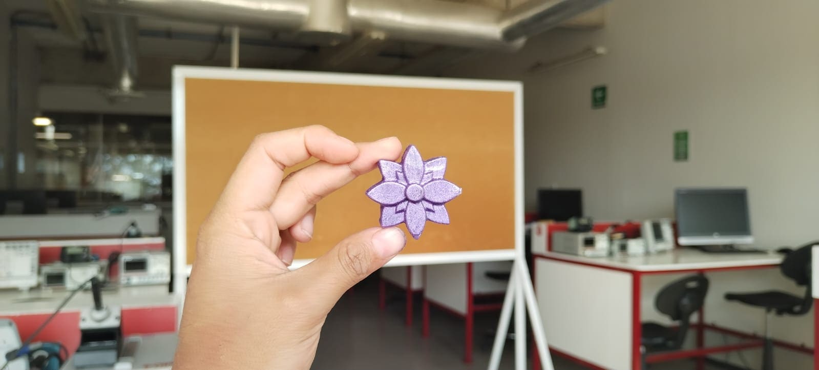
Results

Mistakes and how I solve them
| Problem | How we solve it | One of the problems encountered was that someone accidentally broke the finishing tool I was using. This tool is crucial for achieving a smooth finish on the wax molds. | I had to switch to a different tool for finishing. This unexpected change required adjustments to all the documents and procedures to accommodate the new tool, causing a bit of disruption and extra work. |
|---|---|
| Another issue arose when I was attaching my wax block to the work surface. Unfortunately, I accidentally over-tightened the screws, which caused the base to warp or "pandeo" and resulted in irregularities in the mold. This misalignment affected the quality of the molds, causing them to come out incorrectly. | To resolve this, I had to carefully readjust the entire base setup and reattach the wax block, ensuring the screws were tightened correctly this time. This adjustment was crucial to maintain the stability and alignment of the wax block, preventing further issues with the molds. |
Documents