14. Embedded Networking and Communications
This week was about Communications and embedded networking. It's an interesting week because we can learn how to connect multiple devices.
The group assignment
Here is the group assignment where you can find more about this topic.
Communications
Networking and communications are an important part when making a circuit and want to add more things. On microcontrollers this is very useful and there's a list of type of communications we can use for this.
On this topic, we have UART, SPI and I2Cc
UART is a serial communication protocol that enables asynchronous serial communication between devices. It uses two primary lines, RX (receive) and TX (transmit), allowing for full-duplex communication. UART is widely used for short-distance, low-speed, low-complexity data exchange between microcontrollers and peripherals.

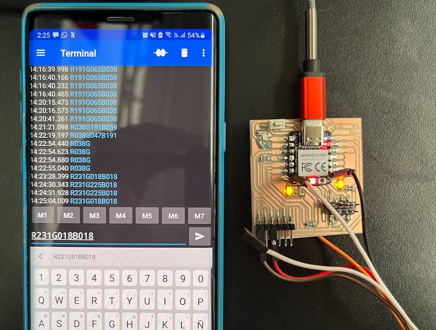
Actually I made one type of this communication on week06 connecting via Bluetooth and changing a Neopixel color using RGB format.
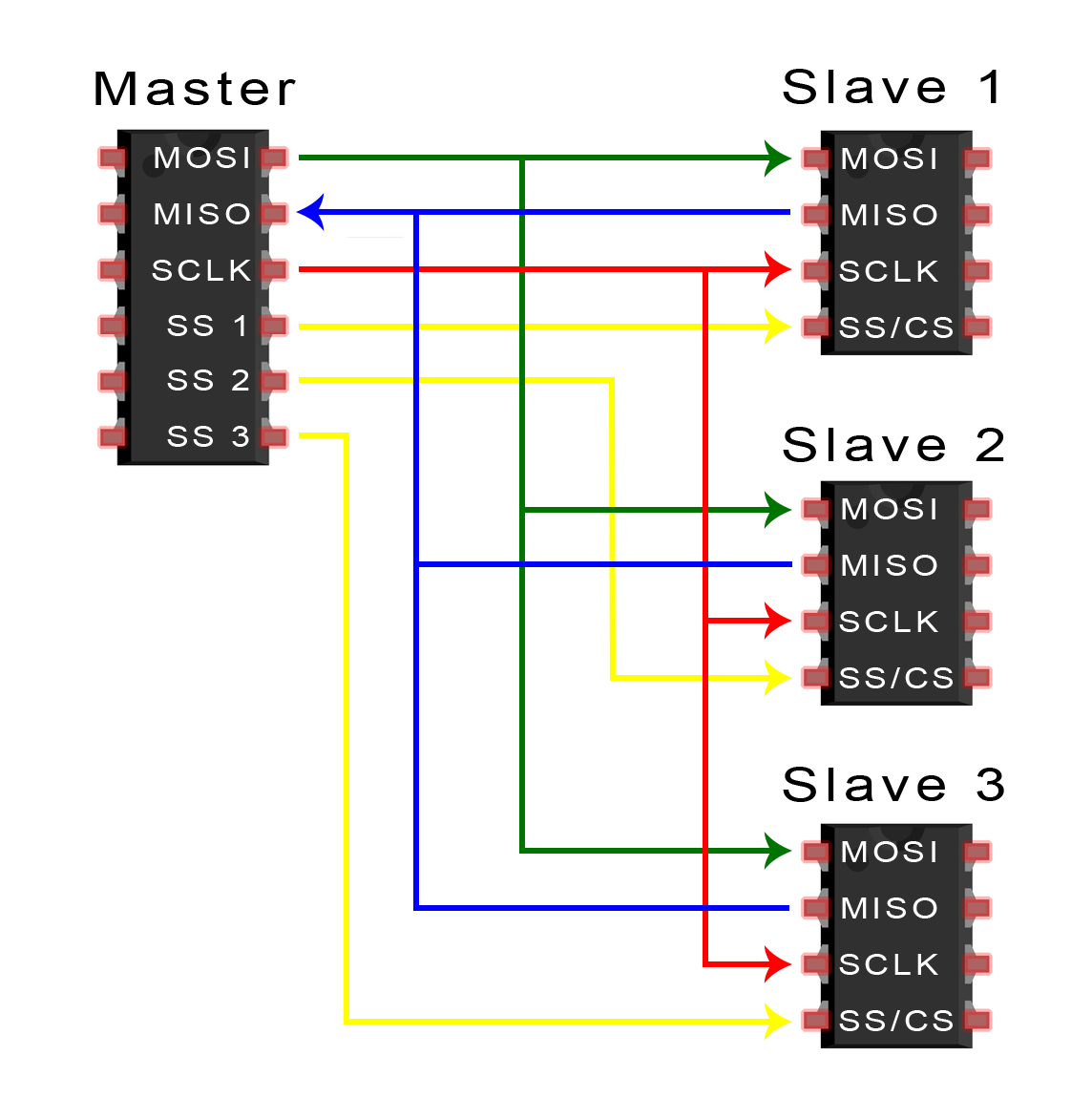
SPI (Serial Peripheral Interface) is a synchronous serial communication interface specification used for short-distance communication, primarily in embedded systems. It operates in full duplex mode and uses a main-secondary architecture. Key lines include SCK (Serial Clock), MOSI (main Out secondary In), MISO (main In secondary Out), and often a SS (secondary Select) for each secondary device.
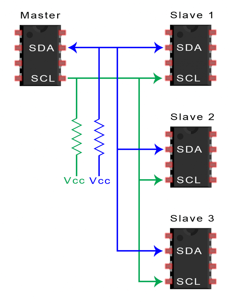
Finally and the one that I used this week, is I2C (Inter-Integrated Circuit) is a multi-main, multi-secondary, packet-switched, single-ended, serial computer bus invented by Philips Semiconductor (now NXP Semiconductors). It's used for attaching low-speed peripherals to processors and microcontrollers in short-distance, intra-board communication.
The components of I2C are:
- SCL (Serial Clock Line): Controlled by the main device, it synchronizes the data transfer between devices on the I2C bus.
- SDA (Serial Data Line): Used for sending and receiving data between the main and the secondary. Both lines are bidirectional.
- Addressing: Each device connected to the I2C bus is assigned a unique address. This allows the main device to select which secondary device to communicate with without any interference from others.
- main and secondary Devices: Any device can function as main or secondary. mains control the clock line and initiate communication with secondaries.
The advantages of I2C are:
- Simple Wiring: Only requires two wires (SCL and SDA), which helps reduce the complexity and cost of the wiring.
- Support for Multiple mains and secondarys: Multiple devices can be connected to the same bus with unique addresses which helps in expanding the system without additional wiring.
- Built-in Error Detection: Uses ACK/NACK signaling and optional CRC checks to ensure data integrity.
The disadvantages of I2C are:
- Speed: Generally slower than SPI, with standard modes typically ranging from 100 kbps to 400 kbps, though higher speeds (up to 3.4 Mbps) are possible.
- Complexity in Handling Collisions: In multi-main configurations, managing bus collisions can complicate firmware.
- Distance Limitations: More suitable for short-distance communication within the same board or closely located devices due to its susceptibility to noise and signal degradation over longer distances.
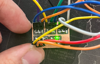
Mini PCB for connections
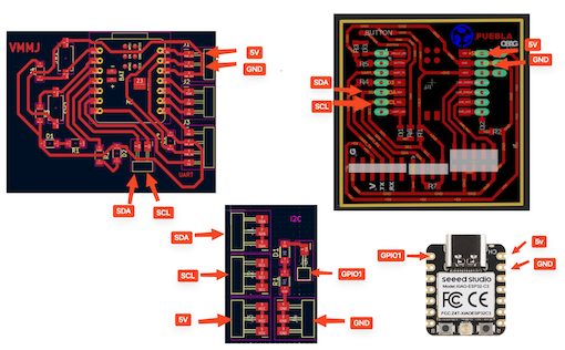
Knowing that I'm going to use I2C, I though it would be a great idea to create a PCB to have all the multi-connections. The 3 SDA, 3 SCL, 3 GND and 3 5V vcc.
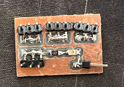
This tiny PCB has a led, resistor for the led and the multi-connection for the I2C communication. Because I want to connect only one XIAO to USB, I need to have a 5V current and Ground, then the common SDA and SCL.
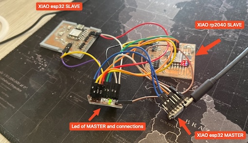
Connecting everything
This is how I'm going to connect everything on this task:
The codes.
As we use I2C communication, we need to configure secondaries and the main. The codes are explained in each line, here are the codes. This codes are going to turn on a led on every PCB using the I2C communication.

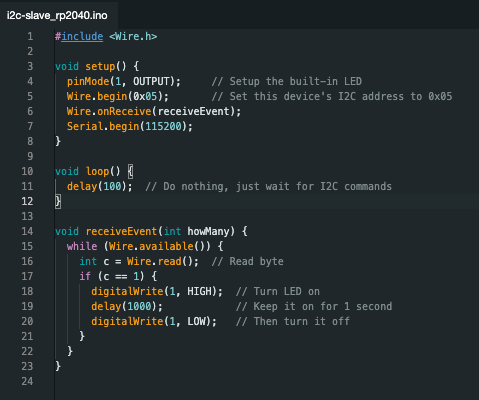
Then we have the two secondaries, here are the codes for each one:
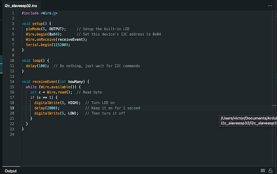
After uploading the codes to every XIAO, lets set everything. Our main is going to be a XIAO esp32 without PCB, just pins.
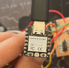
Everything set:
The PCB I made for connect everything:
Let's see everything working...