6. Embedded programming.
On this week we learned how to program on the PCB, the connections, how to use the "drivers" and more.
The group assignment
Here is the group assignment, click here
CODING principles
Let's beging with the basics of programming, for starting I'll be explaining everything on python.
First of all we have variables which are very useful and works as a "bucket" to keep something (a data).
Then we have types of the data, the most important and the ones that are useful for start programming are:
- int: Integer: 0, 1, 2, ... 9, 01, 02, 999...
- str: String: "Hola From Mexico", "Hello global evaluator", "Neil"
- bool: Boolean: True or False
- tuple: tuple: (value1, value2, ... valuen)
- list: list: ['Value1', 'Value2'], [1, 2, 4, 3]
- bytes: binary type
- dict: Dictionary: {"name" : "John", "age" : 36}
bucket_string = 'Hello' #string
bucket_int = 10 #integer
bucket_list = [0, 1, 2] #list
bucket_tuple = (10, 20, 30) #Tuple
bucket_dict = {"name" : "John", "age" : 36} #Dictionary
bucket_bool = True #Boolean

using_list = [bucket_string, bucket_bool] #Example of creating a list with values already created

print(using_list) #Prints the list created before
Then we have basic operations with operators such as +, -, *, /, %, this can be used on numbers and the + on strings. The comparison ones are < , > , ==, those are used to compare values, etc.. All datatypes have their methods. A method is something that "changes" or give information about a datatype. On the next example I'll be using an if statement which check if a condition is true or false:
list_1 = [0, 1, 2] #Creating a list
list_1.append(3) #Using the method append to add a element to the list
print(list_1) #This show the list with the new element: [0, 1, 2, 3]
######################


value1 = 1
value2 = 2
value3 = 1
sum = value1 + value1 #This creates an addition of value1 (1) + value1 (1)
#Result: sum = 2

#Compare if value1 is fewer than value2
if value1 < value2: #Condition
    print("1 is fewer than 2") #Result if true
else: #Else statement: if not the above, this
    print("1 is not fewer than 2")#Case else
Having this little basics on mind, let's start with the beging of this week task, coding a PCB.
coding the pcb
For my final project I want to create a lamp that actually would have a red color and white one. So for this task I decided to program the PCB in order to change color by a cellphone using Bluetooth connection. For this task I'll be using python and cpp, in order to show how the same task can be solved by the two languages.
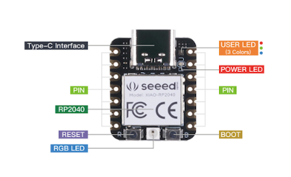
To start is important to know the way in which the XIAO rp2040 works. The XIAO rp2040 works as a raspberry or arduino, you need to "flash" the unity to make it work on python, in order to flash the unity, is needed to connect to a laptop/pc and add to the unity the .uf2 file (USB Flashing format) which is going to be the file that's going to flash the XIAO.
Arduino coding
We will start with Arduino. The first step is to download the arduino IDE. For my individual case and some other classmates, we needed to set-up the XIAO for Arduino. The steps to follow in order to set-up the XIAO RP2040 are the next [*]:
Step 1. Press and hold the BOOT button and then connect the Seeed Studio XIAO RP2040 to the PC.
Step 2. If the "RPI-RP2" disk is shown on the PC and the Power LED on the Seeed Studio XIAO RP2040 is turned on, the connnection is complete. But this was not my case, so needed to continue setting up the software.
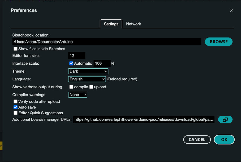
Step 3.Add the XIAO RP2040 to the Arduino IDE: Navigate to File > Preferences, and fill Additional Boards Manager URLs with the next url: https://github.com/earlephilhower/arduino-pico/releases/download/global/package_rp2040_index.json
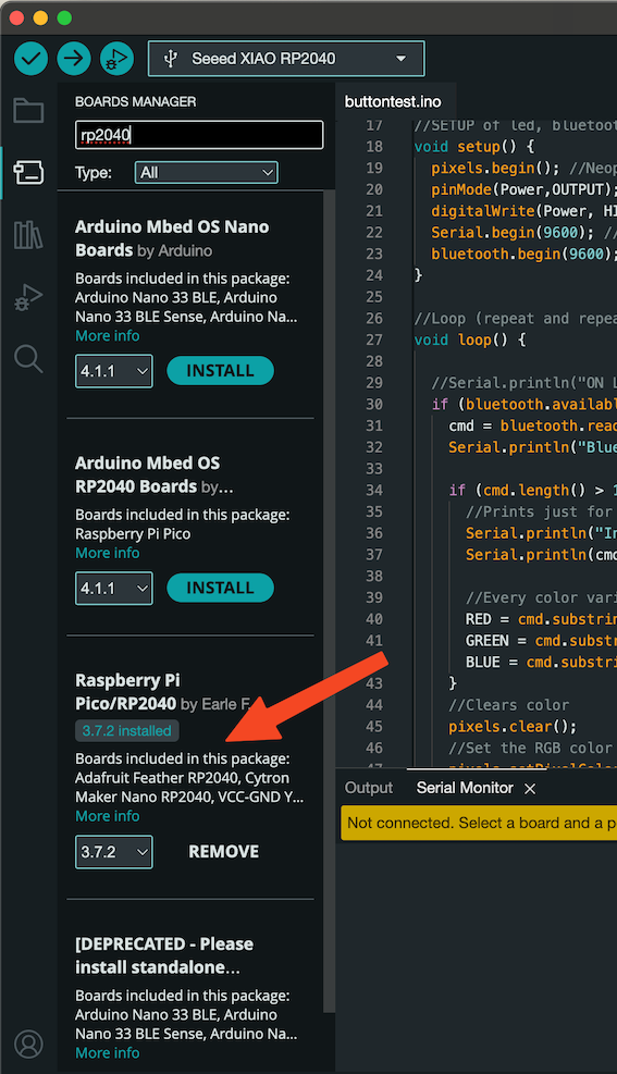
Step 4. Navigate to Tools-> Board-> Boards Manager..., type the keyword "RP2040" in the searching blank. Select the lastest version of "Raspberry Pi Pico/RP2040" and install it.
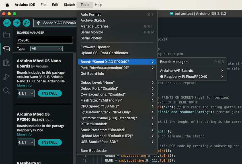
Step 5. Select the board: After installing the board package, navigate to Tools-> Board, find "Seeed Studio XIAO RP2040" and select it. Now we have finished setting up the Seeed Studio XIAO RP2040 for Arduino IDE.
Step 6. Upload it to the XIAO and check if everything is working properly.
The last was provided by Seeedstudio And now, it's time to code the important...
Bluetooth and coding on Arduino
On my board you're going to see things such a push button, leds and pins. For this task I'm only using:
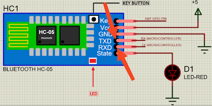
- HC-05 Bluetooth Module.
- Female to Female jumpers
The idea is to turn on different colors using the RGB led that is found on the XIAO RP2040. For turning this on I wanted to be via Bluetooth, this by sending the RGB code from the terminal of a CellPhone. This is important for me because is linked to my final project.
Doing some research, I found that the best way to use the Bluetooth HC-05 component is by using UART.
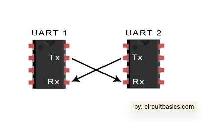
UART stands for Universal Asynchronous Receiver/Transmitter. This is used on physical circuit in a microcontroller. It's main purpose is to transmit and receive serial data.
For communication, two UARTs communicate directly with each other. The transmitting UART converts parallel data from a controlling device like a CPU into serial form, transmits it in serial to the receiving UART, which then converts the serial data back into parallel data for the receiving device. Only two wires are needed to transmit data between two UARTs. Data flows from the Tx pin of the transmitting UART to the Rx pin of the receiving UART.
UARTs transmit data asynchronously, which means there is no clock signal to synchronize the output of bits from the transmitting UART to the sampling of bits by the receiving UART. When the receiving UART detects a start bit, it starts to read the incoming bits at a specific frequency known as the baud rate. Baud rate is a measure of the speed of data transfer, expressed in bits per second (bps). Both UARTs must operate at about the same baud rate. The baud rate between the transmitting and receiving UARTs can only differ by about 10% before the timing of bits gets too far off.
There is more about UART but for this moment with that information is enough.
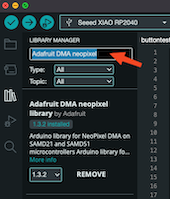
Now for the RGB led, we need to use a library called NeoPixel. On arduino this library is easy to install. Arduino IDE --> Library Manager --> Search "Adafruit DMA neopixel" --> Install it.
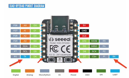
Last for the setup, we connect the Rx from the XIAO to the Tx of the HC-05 and the Tx of the XIAO to the Rx of the HC-05. This by following the next diagram:
The ones for the HC-05:
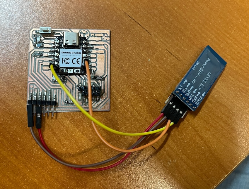
This is how the final circuit after connecting VCC and GND to the PCB looks like:
It's time for the code. This is going to be too much but every line has it explained. The input from the terminal should be a string with the RGB color in the next format R000G000B000. Example: R255G204B153
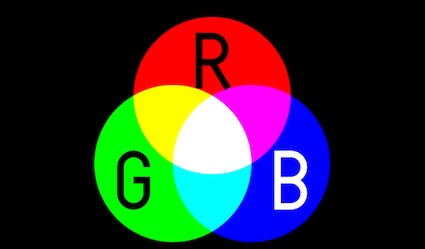
RGB works by an additive color model. In other words, to obtain other colors, you mix the primary red, green, and blue colors. If you mix all three colors at their maximum intensity (100%), you get white. On the other hand, if you mix all of them at their minimum intensity (0%), you get black.
#include < SoftwareSerial.h > //Adding software serial to connect to the bluetooth component. This is UART.
#include < Adafruit_NeoPixel.h > //Adding neopixel to the code to play with the colors
SoftwareSerial bluetooth(1, 0); //Set bluetooth connection
int Power = 11;
int PIN = 12; // The RGB led pin, found on the datasheet.
#define NUMPIXELS 1 //Numbers of pixels we're going to use.
int RED, GREEN, BLUE = 0; //variables that are going to have the RGB code.
Adafruit_NeoPixel pixels(NUMPIXELS, PIN, NEO_GRB + NEO_KHZ800); //Neopixel start
String cmd = ""; //String that will receive from the Bluetooth terminal
//SETUP of led, bluetooth and neopixel
void setup() {
pixels.begin(); //Neopixel setup
pinMode(Power,OUTPUT); // Setting output pin
digitalWrite(Power, HIGH);
Serial.begin(9600); // 9600 specifies the baud rate, which is the rate at which data is transmitted and received
bluetooth.begin(9600); // 9600 specifies the baud rate, which is the rate at which data is transmitted and received
}
//Loop (repeat and repeat and repeat and .... repeat)
void loop() {
//Serial.println("ON Loop"); // PRINTS ON SCREEN (just for testing)
if (bluetooth.available()>0) { //CHECK IF BLUETOOTH
cmd = bluetooth.readStringUntil('\n'); //This reads the string gotten from the bluetooth and add its to cmd until a line jump. \n
Serial.println("Bluetooth available and readUntilString"); //Print just for checking
if (cmd.length() > 10){ //Check if the lenght of the string is the correct.
//Prints just for checking
Serial.println("Into CMD length");
Serial.println(cmd); //Shows on terminal the string
//Every color variable gets it's RGB code by creating a substring and giving the places of the code. This having in mind that the spaces starts from 0.
RED = cmd.substring(1, 3).toInt();
GREEN = cmd.substring(5, 7).toInt();
BLUE = cmd.substring(9, 11).toInt();
}
//Clears color
pixels.clear();
//Set the RGB color to the neopixel
pixels.setPixelColor(0, pixels.Color(RED, GREEN, BLUE));
//Delay for security
delay(400);
//Show the color
pixels.show();
}
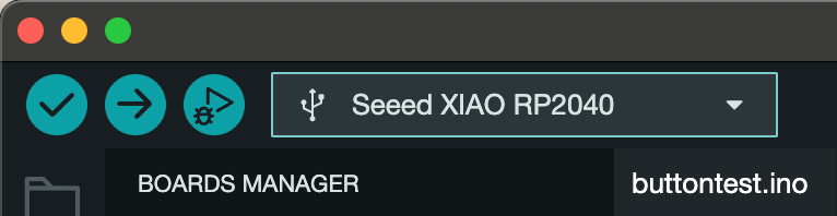
}Upload it to the XIAO with the arrow button.
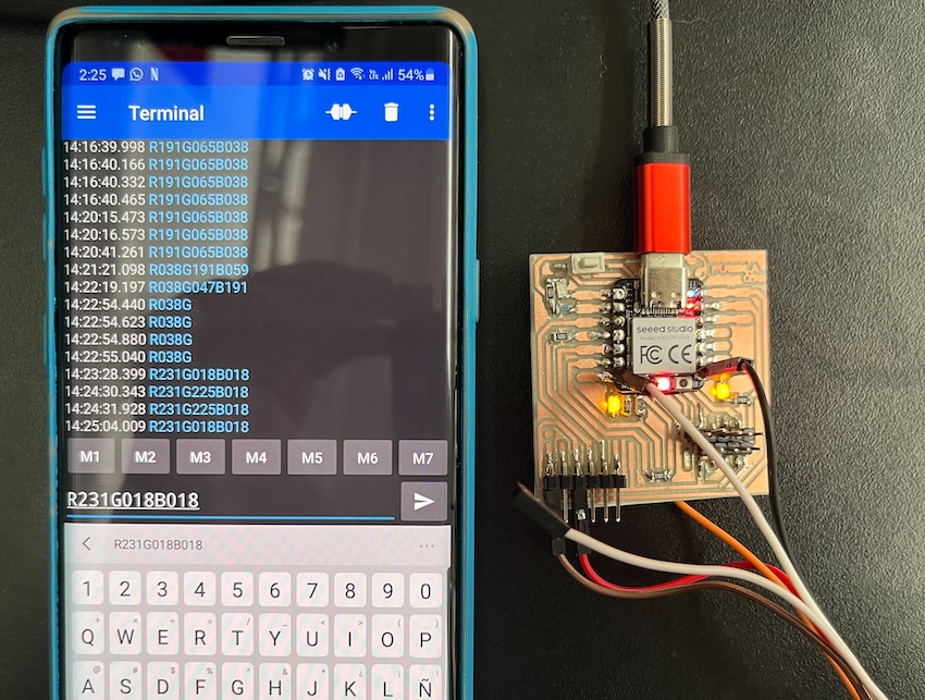
Now it's time to test it. For this I connect a cell to the HC-05 from settings and use an app called APPNAME. After connecting to it the led on the HC-05 stops blinking, now it indicates that we're connected. So let's try a color.
Now let's try with another color:
I played with it some time, let's show here a last color:
That was all with arduino, now let's try it with python.
Python coding using micropython
I did the same using python. Our instructor recommend us as a group to use MU Editor using CircuitPython but because I'm a Mac user, MU Editor has some troubles with my mac so then I prefered to use Thonny with micropython.
Thonny is an IDE that comes with Python 3.10 built in, so just one simple installer is needed and you're ready to learn programming. You can install Thonny on this link.
MicroPython is a lean and efficient implementation of the Python 3 programming language that includes a small subset of the Python standard library and is optimised to run on microcontrollers and in constrained environments. On this task I'll be using MicroPython.
We need first to "flash" the XIAO with the .uf2 file. For this we need to press the boot button on the XIAO while connecting it
to the computer, the we need to drag the UF file to the XIAO, file that you can download here. Finally you
open Thonny and automatically it detects the flashed XIAO. Open there the code.py and you can start programming.
In this case for using Neopixel we need to import the library as a code. This is the code and we need to add it to the Thonny with the XIAO connected.
Then we need to import it the ws2812 on the code.py. So the code of the neopixel with Bluetooth on python is the next (every line is explained)
from ws2812 import WS2812 #Import of NEOPIXEL
import utime
import machine
from machine import UART, Pin #Import of UART to connect to BT
power = machine.Pin(11,machine.Pin.OUT)
power.value(1)
led = WS2812(12,1)#WS2812(pin_num,led_count) #Connect to the RGB LED
uart = machine.UART(0, baudrate=9600, tx=0, rx=1) #Setting UART to bt
while True: #Cicle to await for response
#uart.write("Hello, Bluetooth!\n") to print on BT terminal
utime.sleep(1)
if uart.any(): #Check if uart receive
#Read the data
received_data = uart.read()
#Decode the data because it is given on 'byte' type
clear_data = received_data.decode('utf-8')
# Check the data on the terminal
print("Received:", clear_data, "Type", type(clear_data), len(clear_data))
#Check if the RGB code is given correctly
if len(clear_data) == 14:
#GET THE red RGB code (numbers after the "R")
red = int(clear_data[1:4])
#GET THE red RGB code (numbers after the "G")
green = int(clear_data[5:8])
#GET THE red RGB code (numbers after the "B")
blue = int(clear_data[9:12])
#Checking if we get all correct
print(red, green, blue)
#filling with neopixel (needs to be an array of the RGB code)
led.pixels_fill((red, green, blue))
#Showing the color
led.pixels_show()
utime.sleep(0.2)
#Case the RGB code wasnt complete
else:
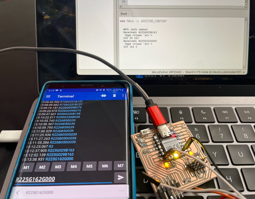
print("Not complete RGB code")That code is charged on the XIAO and running looks this:
Video of the code running:
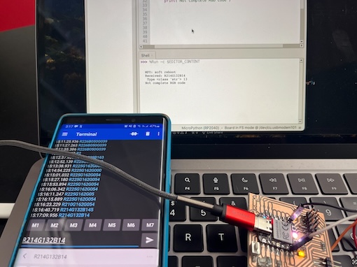
More examples:
Observations
Both ways of coding (python and c++) are good options for developing and programming but the c++ option using arduino is easier to manipulate and the libraries has a better way to access. For me, coding on python was kind of easy because is a language that I use everyday. Is important to add that using a Macbook and a apple enviroment make things a little more difficult. I couldn't use my Iphone to connect with the HC-05, so that's something to consider and finally, considering to put prints on your code or checkpoints is very useful in order to test almost everyline and check where could the mistake be.