Measure something: add a sensor to a microcontroller board that you have designed and read it.
Board design
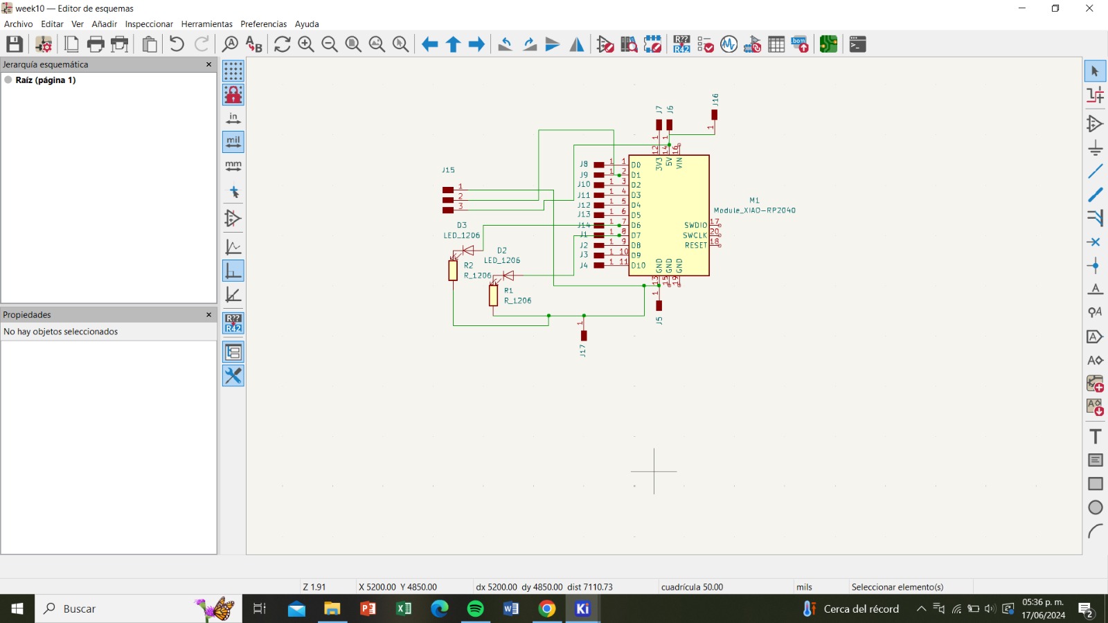
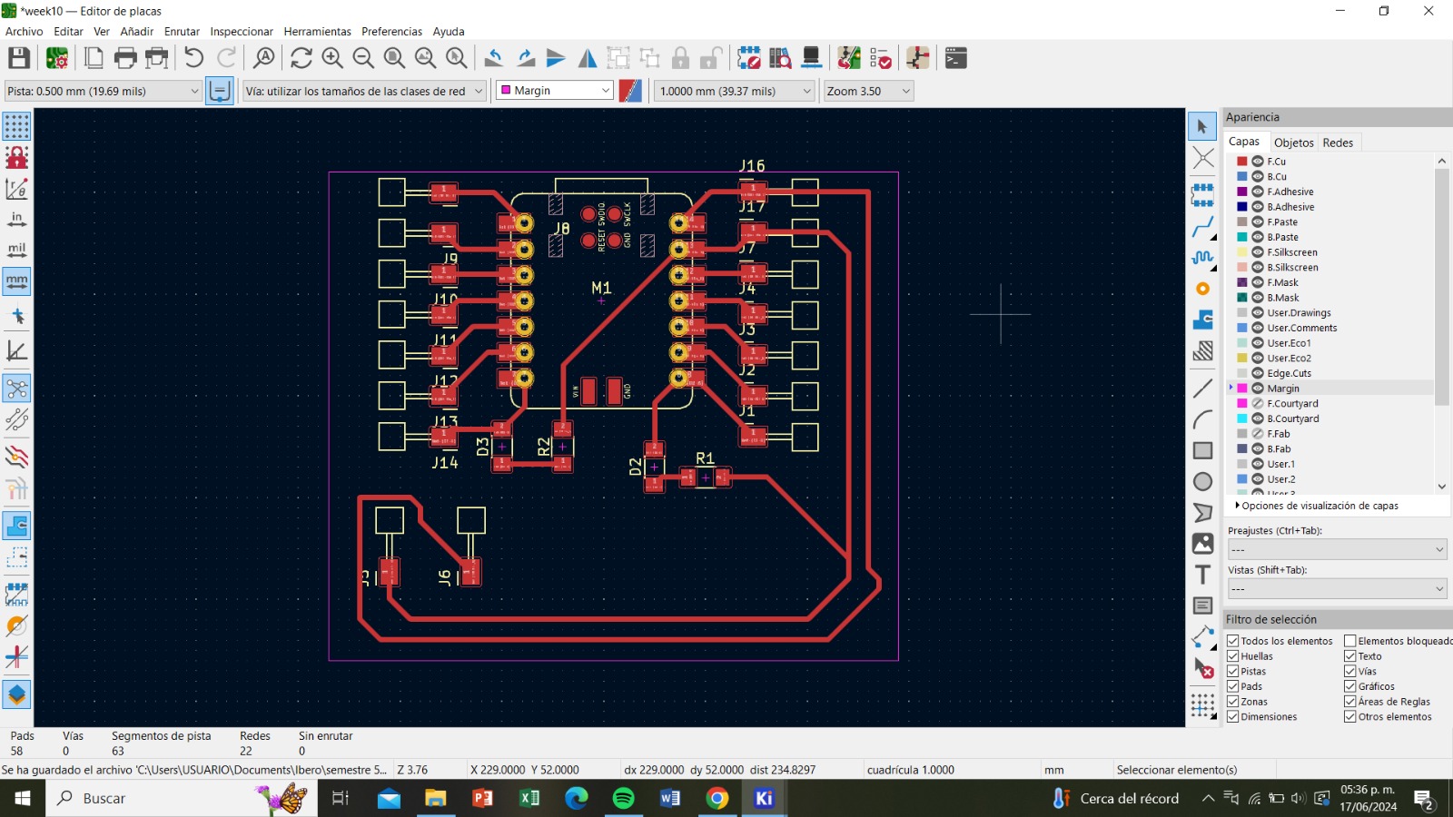
For this week, I designed a board for a Xiao RP2040.
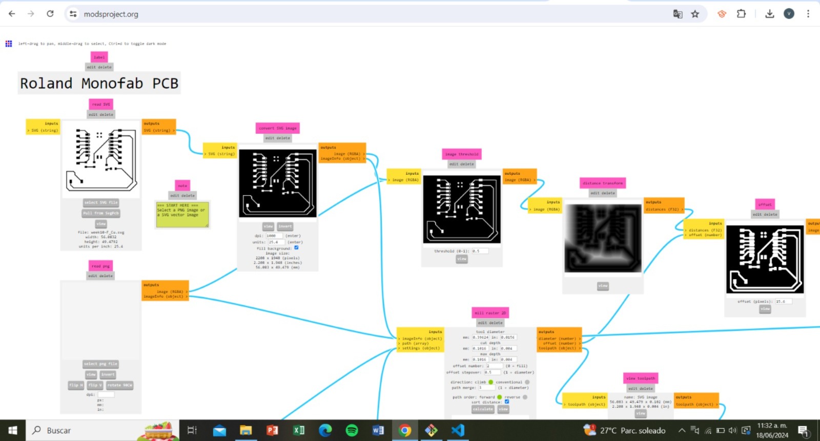
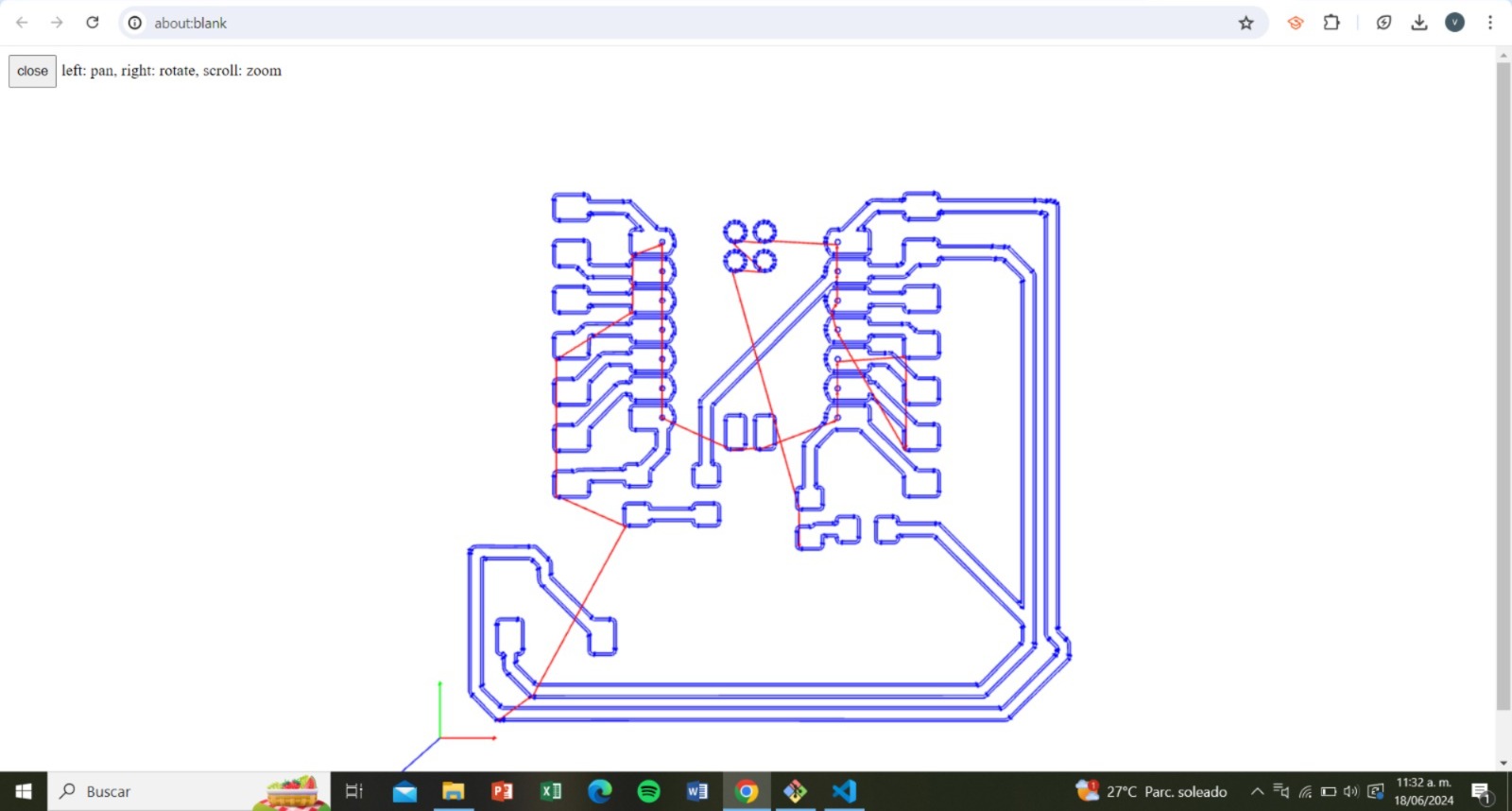
I sent it to Moods to later cut and solder it.
Connections
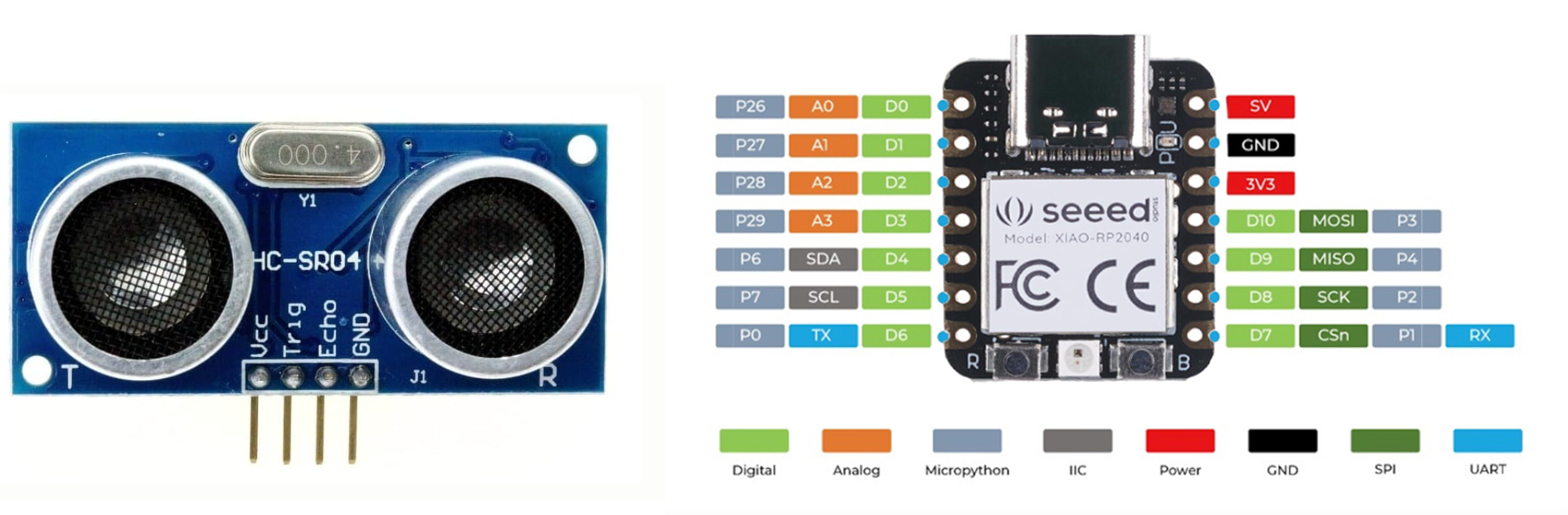
Connection of the HC-SR04 Sensor to the XIAO RP2040:
VCC of the HC-SR04 to 5V of the XIAO RP2040
GND of the HC-SR04 to GND of the XIAO RP2040
Trig of the HC-SR04 to a GPIO pin of the XIAO RP2040 (D4)
Echo of the HC-SR04 to another GPIO pin of the XIAO RP2040 (D5)
Code
The code will be written in Arduino IDE and the Arduino IDE serial monitor will display the distances measured by the ultrasonic sensor
to measure distance and controls several LEDs based on that distance. Below is the detailed explanation of the programming process of the code:
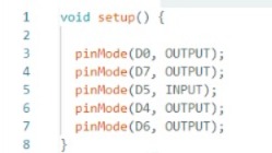
Pin Configuration
In the 'setup()' function, we configure the modes of the microcontroller pins: D0, D7, and D6 are set as outputs, presumably to control LEDs.
D5 is set as an input to receive the signal from the ultrasonic sensor.
D4 is set as an output to send the trigger pulse to the ultrasonic sensor.
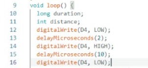
Main Loop
In the loop() function, the following operations are performed continuously:
1. Sending the Trigger Pulse
The D4 pin is set to low (LOW), then high (HIGH) for 10 microseconds, and then back to low.
This pulse is necessary to initiate the distance measurement on the ultrasonic sensor.
2. Measuring the Echo Time
'pulseIn(D5, HIGH)' measures the time that the 'D5' pin remains high, i.e.,
the time it takes for the echo pulse to return to the sensor. This time is stored in the 'duration' variable.
3.Calculating the Distance
The distance is calculated using the formula: distance = (echo time * speed of sound) / 2. The speed of sound is
approximately 343 m/s or 0.0343 cm/µs. We divide by 2 because the measured time is for the round trip.
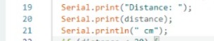
Printing the Distance:
The measured distance is printed to the serial monitor.
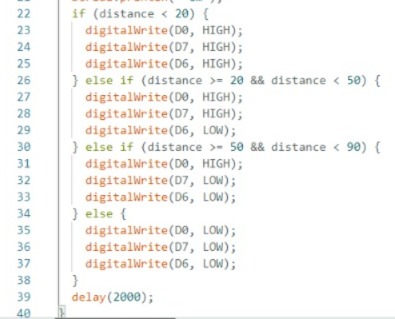
Controlling the LEDs Based on the Distance
Depending on the measured distance, the LEDs connected to pins D0, D7, and D6 are controlled:
If the distance is less than 20 cm, all LEDs are turned on.
If the distance is between 20 and 50 cm, only D0 and D7 are turned on.
If the distance is between 50 and 90 cm, only D0 is turned on.
If the distance is 90 cm or more, all LEDs are turned off.
Pause Before the Next Measurement:
A 2-second pause is introduced before measuring the distance again.

