Embedded Networking and Communications
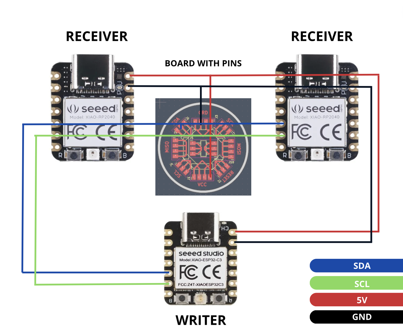
For this week's assignment, I've chosen to establish communication between the latest board I designed, the XIAO ESP32C3, and my two initial boards, both equipped with XIAO RP2040. This connection will be achieved using the NeoPixels integrated into each board, along with an additional pin board designed to facilitate all necessary connections. All of this will be possible thanks to the implementation of the I2C communication protocol.
Team Practice
Here its the link of our team practice.
COMPONENTS LIST
| Components | |
|---|---|
| Board with XIAO RP2040 | 2 |
| Board with XIAO ESP32C3 | 1 |
| Board with pins | 1 |
These are the components I used for this week.
I2C communication protocol
Understanding the I2C Protocol:
The I2C protocol involves two main lines: SDA (Serial Data Line) for data transmission and SCL (Serial Clock Line) for data synchronization. Each device on the I2C bus has a unique address.
Configure the writer device (ESP32C3)
This code sets up the ESP32C3 as the "writer" device on the I2C bus. It sends commands to turn on and off the "receivers" through specific I2C addresses.
#include

#define RECEIVER_1_ADDRESS 1   // Dirección I2C del primer receptor
#define RECEIVER_2_ADDRESS 2   // Dirección I2C del segundo receptor

void setup() {
    Wire.begin(); // Inicializa la comunicación I2C como "writer"
}

void loop() {
    sendMessage(RECEIVER_1_ADDRESS, 1); // Enciende el primer receptor (dirección 1) con color púrpura (1)
    delay(1000);
    sendMessage(RECEIVER_1_ADDRESS, 0); // Apaga el primer receptor (dirección 1) con color azul (0)
    delay(1000);
    sendMessage(RECEIVER_2_ADDRESS, 1); // Enciende el segundo receptor (dirección 2) con color púrpura (1)
    delay(1000);
    sendMessage(RECEIVER_2_ADDRESS, 0); // Apaga el segundo receptor (dirección 2) con color azul (0)
    delay(1000);
}

void sendMessage(int address, byte value) {
    Wire.beginTransmission(address); // Inicia la transmisión hacia el receptor con la dirección dada
    Wire.write(value); // Envía el valor al receptor
    Wire.endTransmission(); // Finaliza la transmisión
}
Configure the "receiver" devices (XIAO RP2040).
This code sets up the XIAO RP2040 devices as "receivers" on the I2C bus. When they receive an I2C message, they turn on or off the Neopixel according to the message value.
#include
#include

int Power = 11;
int PIN = 12;
#define NUMPIXELS 1
#define I2C_ADDRESS 1   // Dirección I2C del receptor

Adafruit_NeoPixel pixels(NUMPIXELS, PIN, NEO_GRB + NEO_KHZ800);
byte I2C_OnOff;

void setup() {
    Wire.begin(I2C_ADDRESS);    // Inicia la comunicación I2C como receptor con dirección 1
    Wire.onReceive(BlinkLED);   // Configura la función de llamada cuando se recibe un mensaje I2C

    pixels.begin();             // Inicializa la comunicación con el Neopixel
    pinMode(Power, OUTPUT);
    digitalWrite(Power, HIGH);
    pixels.setBrightness(50);   // Establece el brillo del Neopixel (0-255)
    pixels.show();              // Actualiza el Neopixel para mostrar cualquier cambio
}

void loop() {
    // No necesitas ejecutar ningún bucle aquí, ya que el Neopixel se controla mediante I2C
}

void BlinkLED(int Press) {
    I2C_OnOff = Wire.read(); // Lee el mensaje I2C recibido

    // Activa o desactiva el Neopixel según el mensaje recibido
    if (I2C_OnOff == 1) {
        pixels.clear();
        pixels.setPixelColor(0, pixels.Color(103, 25, 205)); // Púrpura
        pixels.show();
    } else if (I2C_OnOff == 0) {
        pixels.clear();
        pixels.setPixelColor(0, pixels.Color(12, 66, 101)); // Azul
        pixels.show();
    }
}
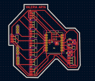
Board connection
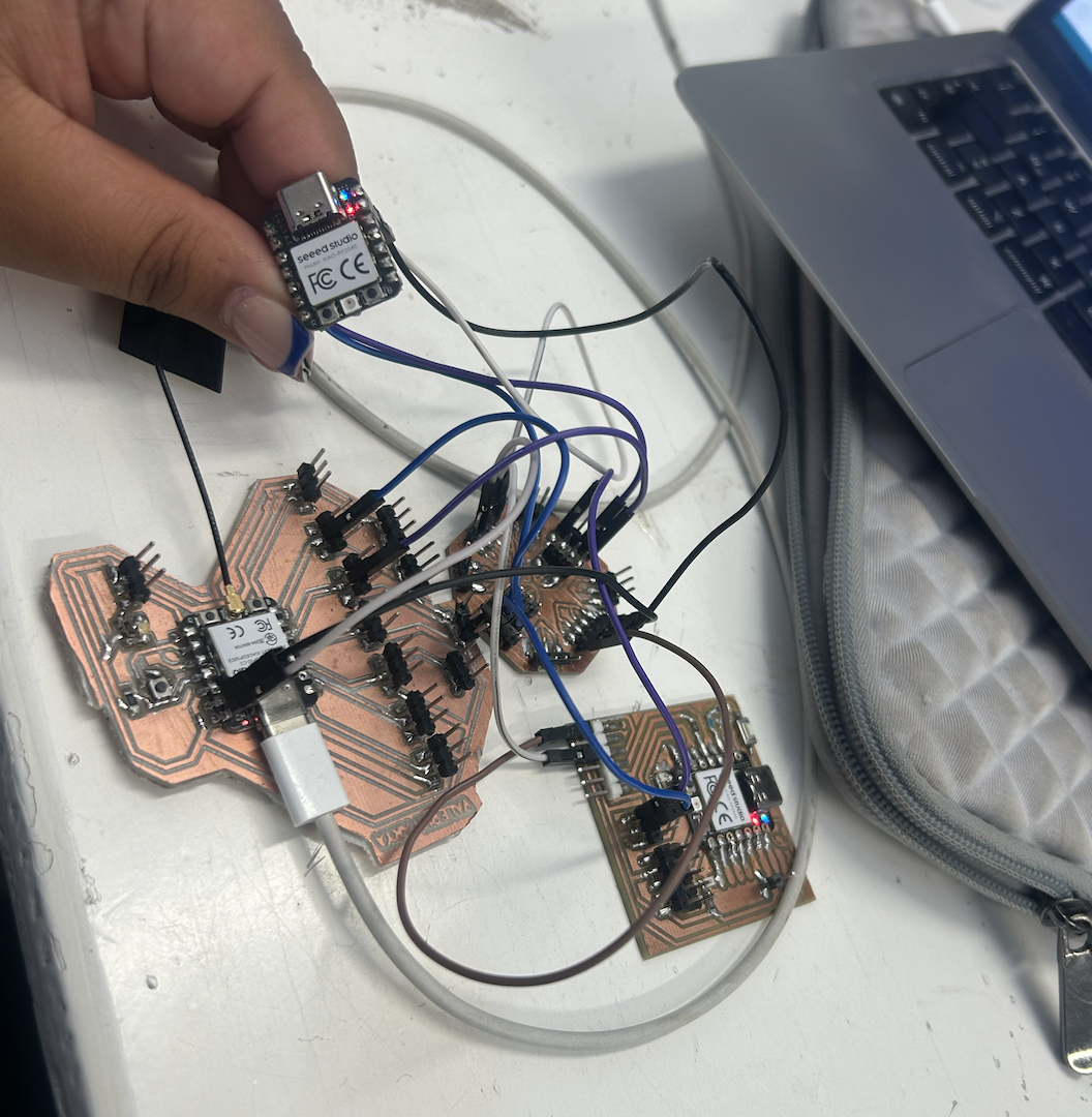
To connect the "writer" (ESP32C3) and "receiver" (XIAO RP2040) devices, I used jumpers and a PCB designed by myself. I carefully connected the data (SDA) and clock (SCL) lines between both devices, following the recommended connection scheme for the I2C bus. I made sure all connections were securely fitted and free from short circuits to ensure smooth communication between the devices.
FINAL RESULT
To connect the "writer" (ESP32C3) and "receiver" (XIAO RP2040) devices, I used jumpers and a PCB designed by myself. I carefully connected the data (SDA) and clock (SCL) lines between both devices, following the recommended connection scheme for the I2C bus. I made sure all connections were securely fitted and free from short circuits to ensure smooth communication between the devices.