Electronics Production
This is the process of engraving, cutting, soldering, and programming my electronic board.
Team Practice
Here its the link of our team practice.
COMPONENTS LIST
| Component | Function |
|---|---|
| Weller soldering station | Main tool for soldering. |
| Soldering iron(tin) | Material that enables the soldering of components. |
| 1k resistor | This one adjust the voltage for the others components" |
| 2k resistor | This one adjust the voltage for some components |
| LED component | Turns on a light within the system. |
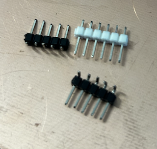
| Male headers | They are used to establish electrical connections between printed circuit boards (PCBs), modules, or electronic devices. |
Step 1
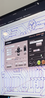
Before starting the process, download the program for the machine that will cut and engrave my design, a "ROLAND SMR-20," which is essentially a mini mill.
Step 2
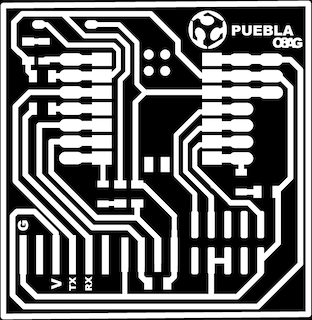
Also, download the PNG files that I will use in the "Mods" program to convert the information for the "ROLAND SMR-20." I have the two engraving and cutting files ready.

Step 3
Next, open the "modsproject" page, where interaction between the program and what we want to cut and engrave takes place to obtain the file we'll send to the SRM-20 cutter.
Step 4
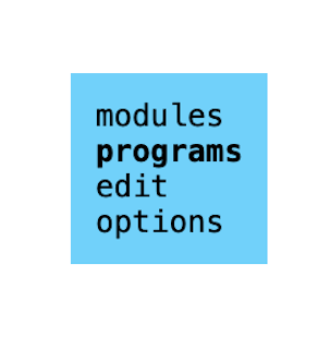
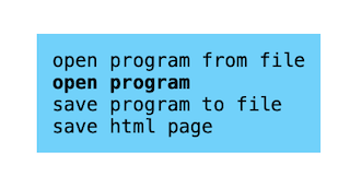
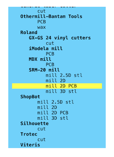
Within the "Mods" program, right-click to access the menu, select "programs," then "open program," and choose the machine in this case, a "mill 2D PCB."
Step 5
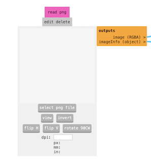
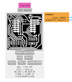
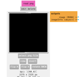
Once in the program, navigate to the area where I would add my PNG image, in this case, the engraving.
Step 6
With the image inside, I proceeded to adjust some parameters.
Step 7
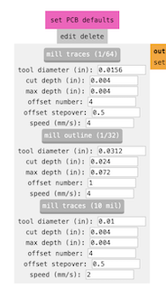
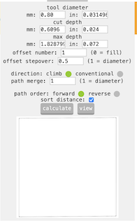
The first parameter I checked was in the "set PCB default" section, ensuring that "mill traces" was set to 1/64.
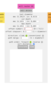
Step 8
I then moved to the "mill raster 2D" section and changed the offset number to "2.Select 2 offsets so that the part that engraves the plate can pass enough to engrave without any issues and without drilling it.
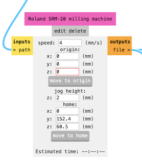
Step 9
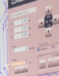
Next, I went to "Roland SRM-20 milling machine" and set the X, Y, Z parameters to 0 to mark an origin point.
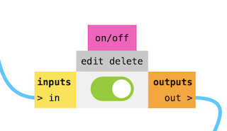
Step 10
I went to Inputs and Outputs, turning it on.
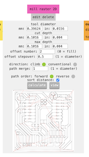
Step 11
Returning to the "mill raster 2D" section, I clicked the "calculate" button to generate the document for the machine and downloaded it in .rml format.
Step 12
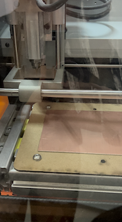
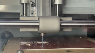
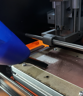
With the format ready, I prepared my MDF board, matching the machine's size, and attached a copper plate for engraving and cutting. I secured the board in the machine with screws.
Step 13
Once adjusted, I returned to the computer, opened the "VPanel for SMR-20" program, closed the machine door, and it calibrated automatically.
Step 14
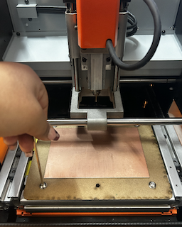
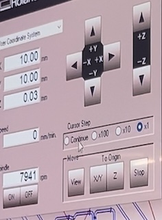
Using the program arrows, I positioned the engraving tip in the lower-left corner, marking X, Y parameters at 0 as the origin, and then set the Z point using a metric M2 key.
Step 15
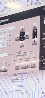
I changed the cursor to "x100" in the program to lower the Z origin slowly, avoiding collision with the piece.
Step 16
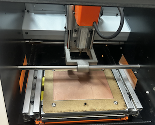
To ensure the Z origin is well-defined, I started the program, waited for the necessary revolutions, and gradually lowered the Z point until it touched the material, marking Z as 0.
Step 17
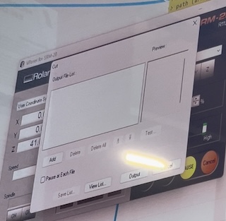
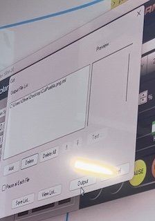
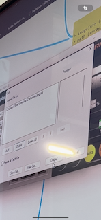
Moving to "Cut," I selected "add," added the previously saved file, and then selected "Output."
Step 18
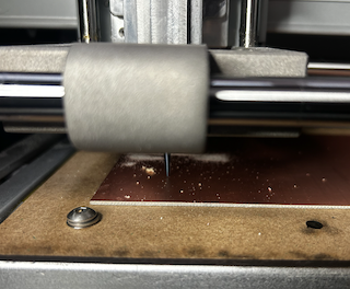
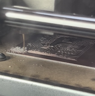
The program automatically started engraving.
Step 19
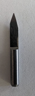
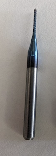
After a few seconds, it became apparent that it only started engraving and didn't continue. We had to stop the program, check, and realized the new engraving tip had worn out. We reconfigured the Z origin point, and it worked correctly.
Step 20
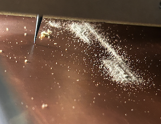
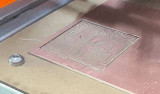
After 18 minutes, the piece finished engraving.
Step 21
I returned to the "Mods" program, repeated the process with the cutting contour PNG file.
Step 22
Added a new PNG, inverted it to cut only the line without affecting the previously engraved part.

Step 23
Changed the thickness of my cutting piece to 0.80mm.
Step 24
Clicked "calculate," downloaded the file again.

Step 25
In the program, adjusted the XY origin, pressed a button, and it adjusted automatically. Raised the Z again to switch from the "engrave" to the "cut" piece, carefully lowering and manually adjusting to avoid collisions.
Step 26
Marked the Z origin again, went to "cut," deleted the previous file, added the new file, and clicked "output." The cutter started descending automatically and cut the board.
Step 27
Once finished, opened the machine door and used a handheld vacuum to clean the dust, leaving the engraved and cut board free.
What I learned
Throughout my experience with the Roland SMR-20 program and machine, I have significantly expanded my skills in cutting and engraving copper plates. The program facilitated the creation of detailed designs, while the machine demonstrated its ability to make precise cuts and fine engravings. Each session was a practical lesson that honed my skills and brought me closer to mastery in crafting unique and meaningful copper plates. This technical and creative journey has enriched my passion for artistic creation.
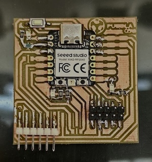
Board soldering
Here its my Board solding process .
Step 1
With the engraved and cut board, I first practiced my soldering on another board to avoid damaging mine.
Step 2
Once ready, I selected the components for the next soldering.
Step 3
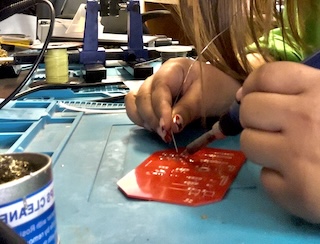
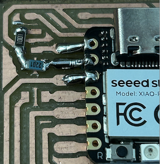
I used a soldering iron and solder to solder each of my components. I set my soldering iron at a temperature of 300 degrees and started from the inside, soldering outward to avoid complications.
Step 4
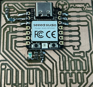
This was the first thing I soldered, and with these components ready, I moved on to those on the underside and finally to the pins. I used a pair of tweezers to bend them at a 90-degree angle to ensure they were aligned.
Step 5
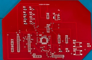
And that's how my soldered board was ready.
Board programming
Here its my Board programming process .
Step 1
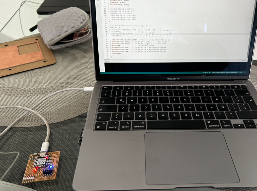
First, ensure that my board will work by checking the soldering when connecting it to my computer.
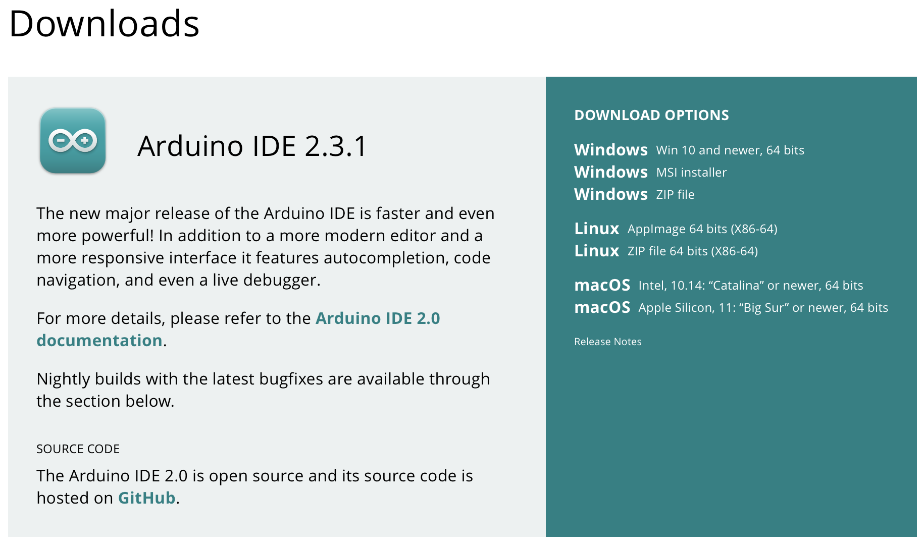
Step 2
With my board ready, I downloaded the program to be able to program my board, "ARDUINO IDE."
Step 3
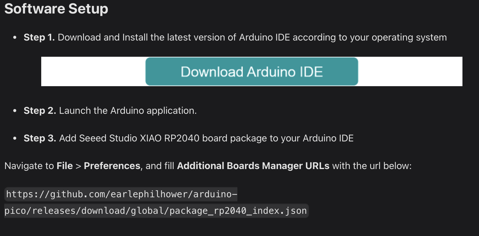
Once the program was downloaded, I had to install a board manager for my XIAO RP2040, so I searched the internet for that manager and copied the link.
Step 4
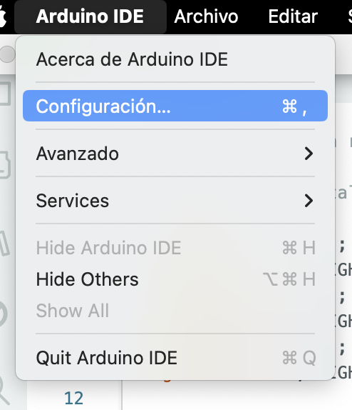
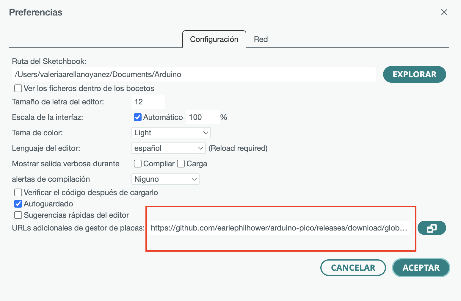
With the copied link, I returned to the Arduino program and went to the advanced settings, where I navigated to Additional URLs and pasted my link, then clicked "OK."
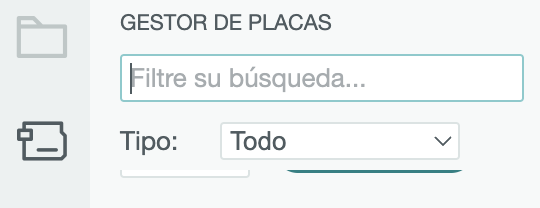
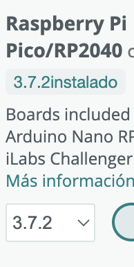
Step 5
Next, I went to the board manager and typed "Raspberry Pi" in the search bar to install the "RP2040" version.
Step 6
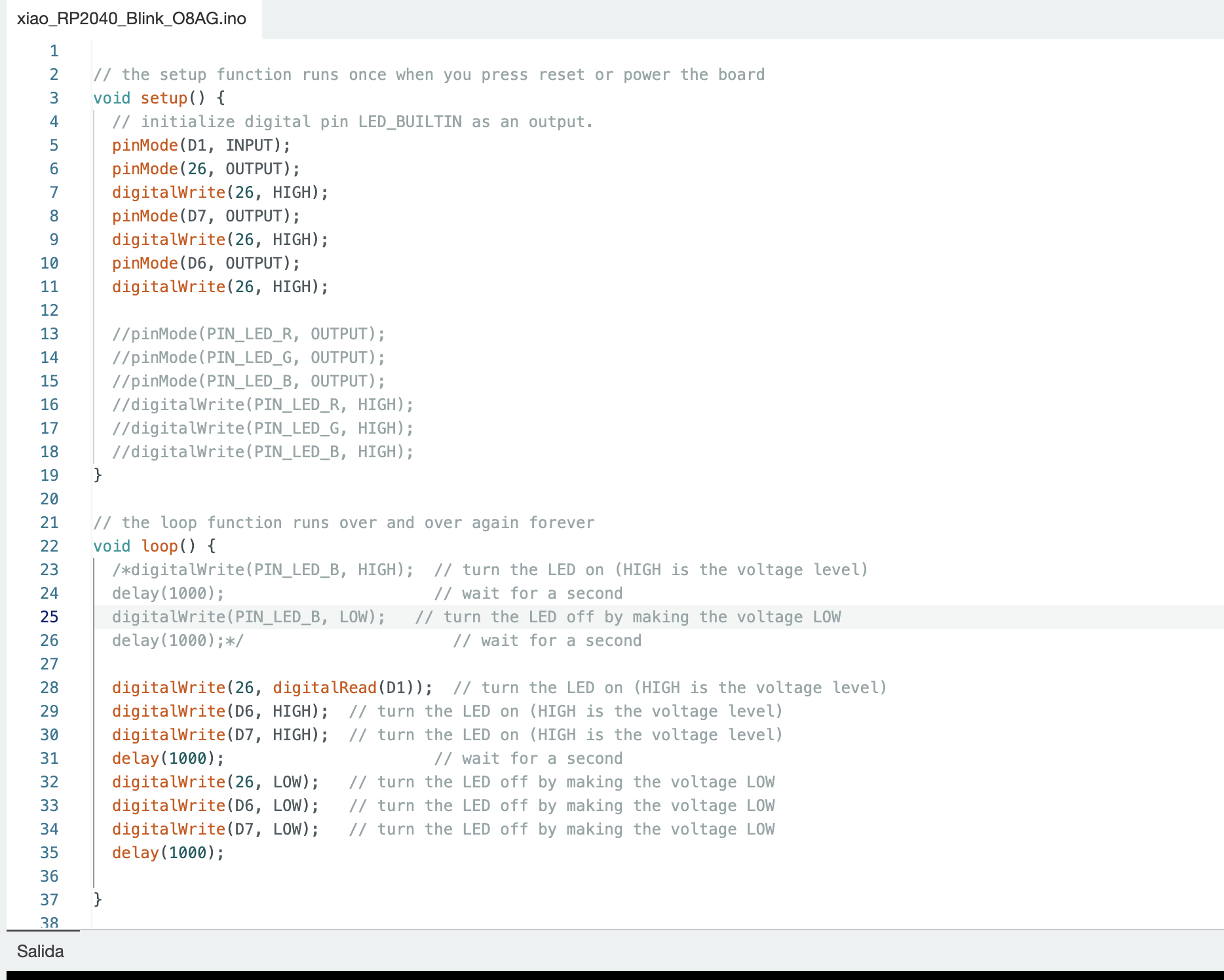
Once installed, I downloaded the test code provided by Fab Lab Puebla.
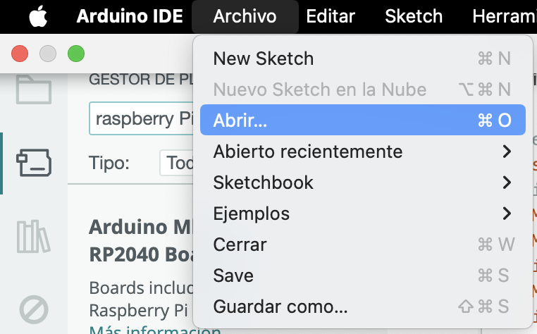
Step 7
I went to "File," then "Open File," and selected my test document.
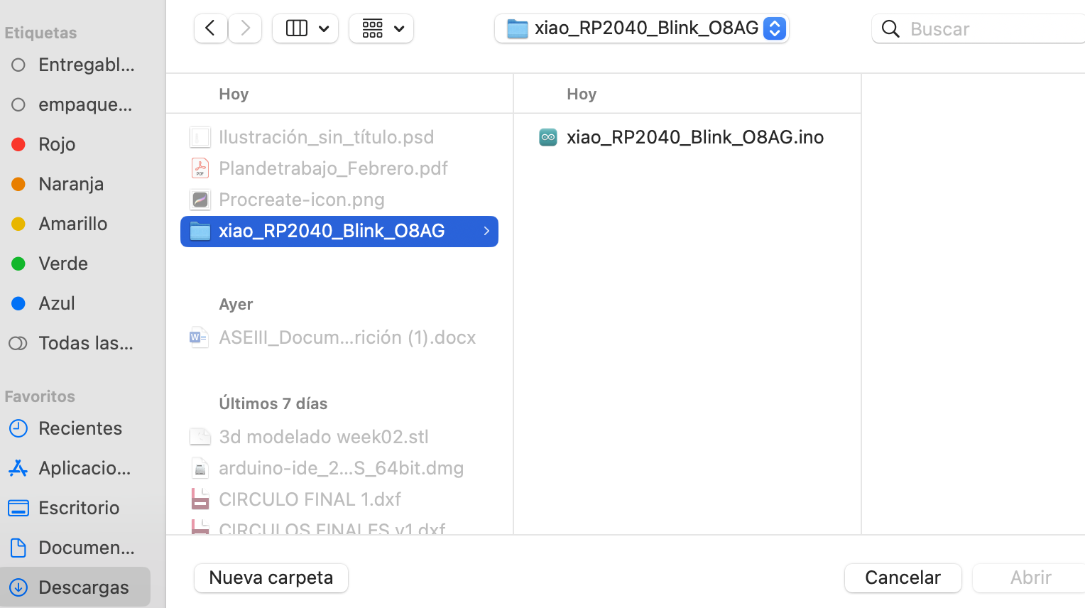
Step 8
It opened, and the code appeared.
Step 9
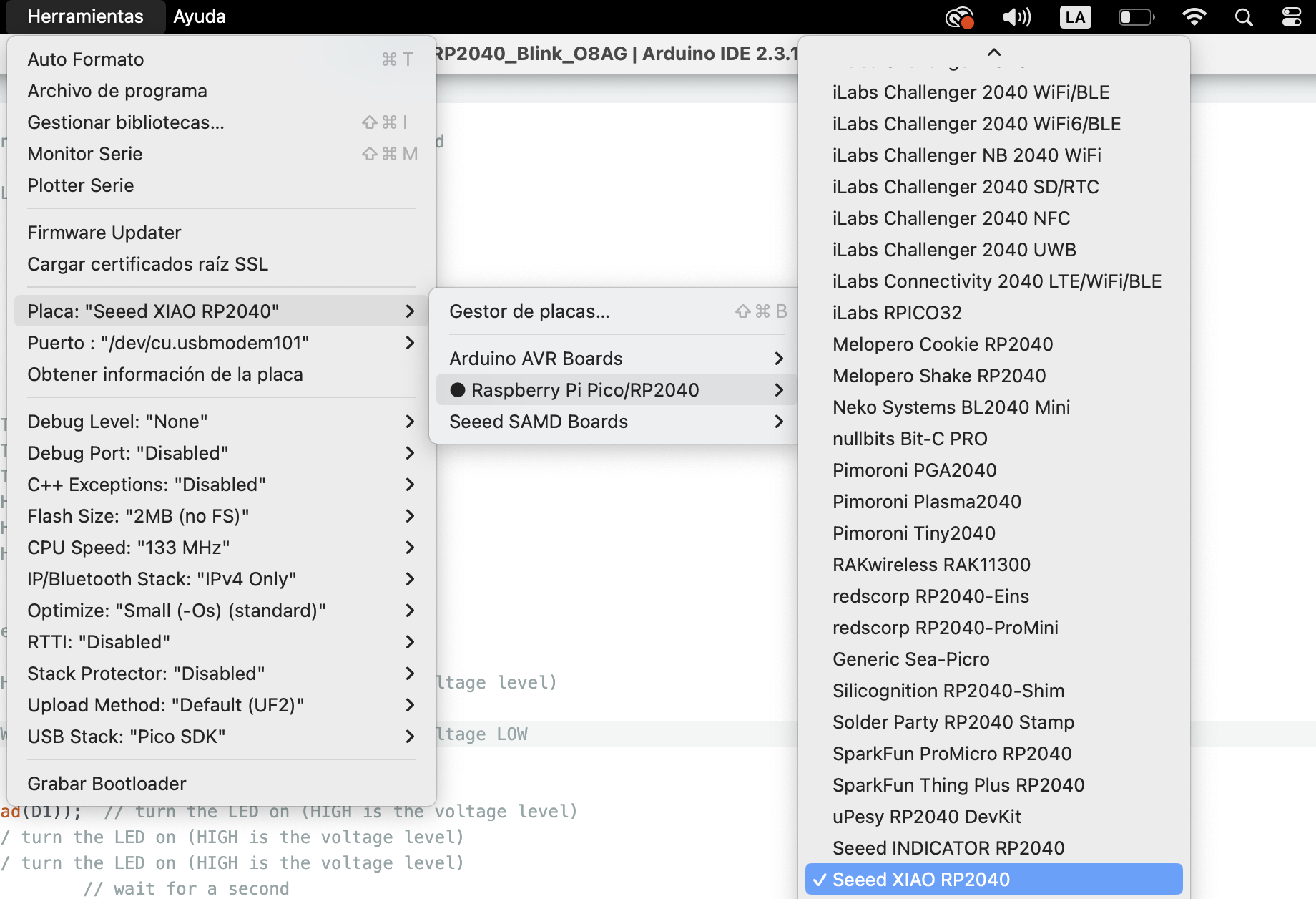
After that, I connected my board to the computer and went to "Tools/Board/Raspberry Pi Pico/RP2040/Seeed XIAO RP2040" and selected it.
Step 10
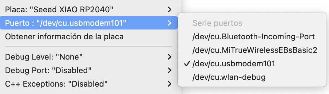
Then, I selected my port in "Tools/Port/dev/cu.usbmodem101."
Step 11
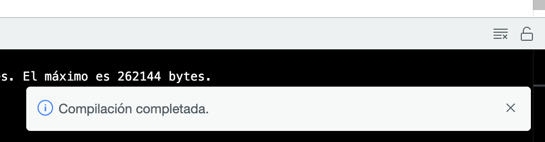
I went back and in the top right corner selected the "Verify" icon, and the code was verified with a message of "successful compilation."

Step 12
I then selected the upload code icon next to it and received the message "upload complete."

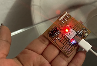
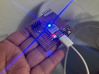
Step 13
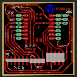
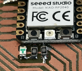
I could see that my board was ready, where basically both bottom LEDs lit up simultaneously, and when you pressed the button, the first LED had to light up only at that moment.