Computer controlled Cutting - Construction Kit
Here its my Computer controlled Cutting design process of my construction kit .
Step 1
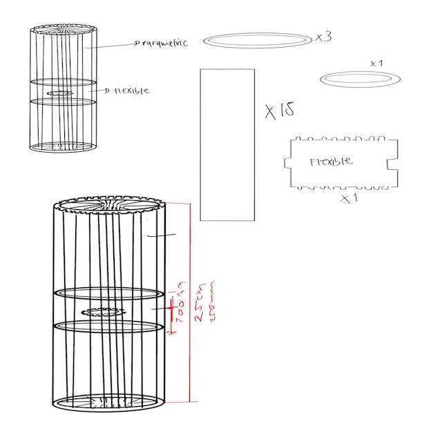
First, I created a design in Procreate with my idea and possible measurements for my construction kit.
Step 2
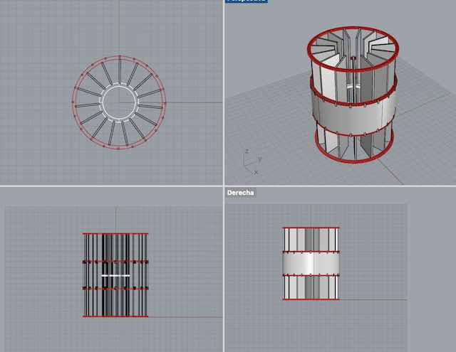
Next, I modeled my idea in Rhinoceros to determine if the joints I was creating would be feasible with the shape of my design.
Step 3
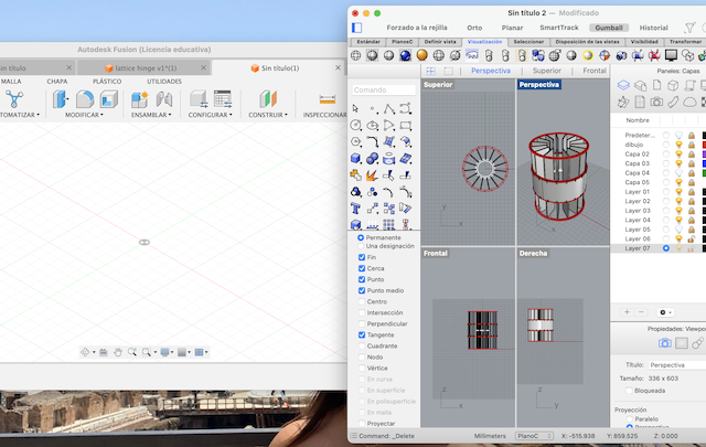
After this, I created a new document in Fusion 360.
Step 4
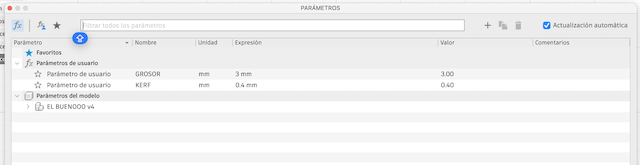
I added two new parameters, one for the thickness of my material, which in this case is 3mm acrylic, and another parameter to account for the laser cutting KERF, set at 0.4mm.
Step 5
I started with a new sketch in the top view to begin the components of my construction kit.
Step 6
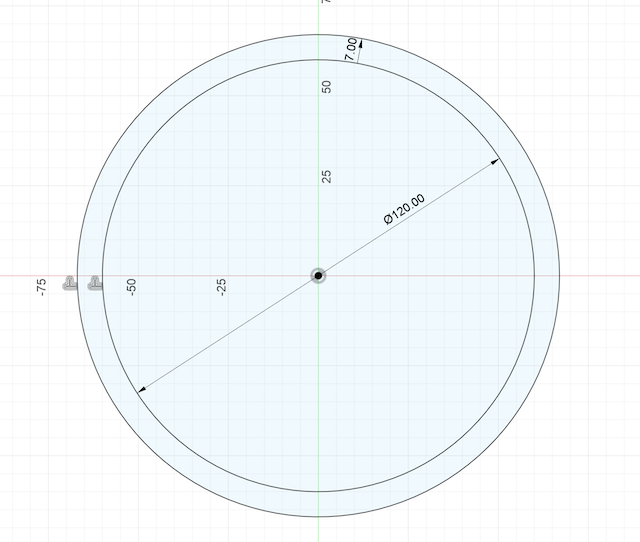
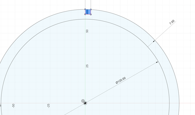
I began by creating circles since I need four of them to form the structure of my proposal.
Step 7
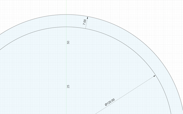
I applied a 7mm offset to my circle.
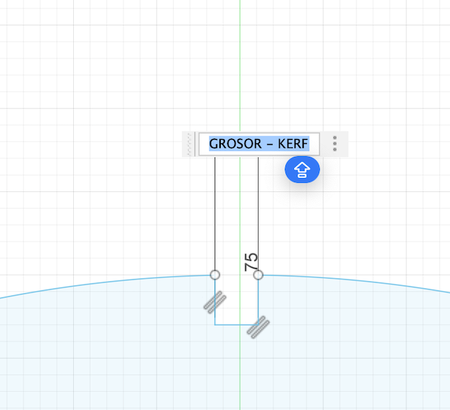
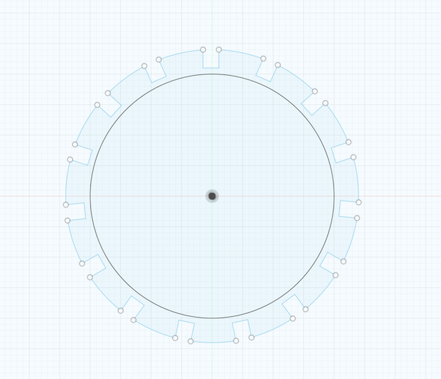
Step 8
I started the assembly design on this piece, drew a line down the middle, applied a 2mm offset, and similarly to the curve of the first offset, I applied a 3.5mm offset. I used the cutting tool just before cutting the part where the assembly would go. I applied a circular pattern of 15 pieces around the circle, then cut, leaving the outer assembly.
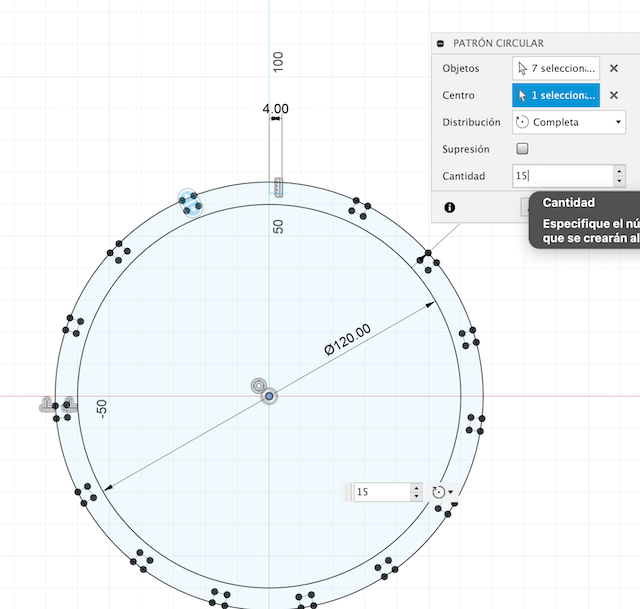
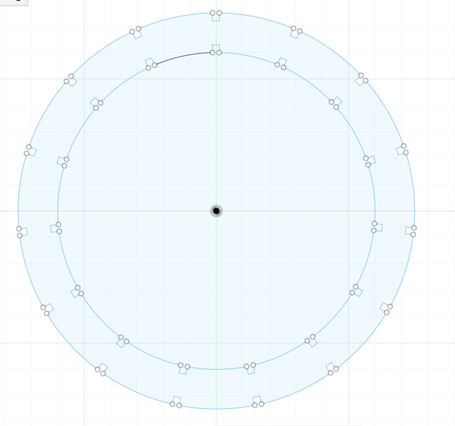
Step 9
I did the same but with the inside part of the circle.
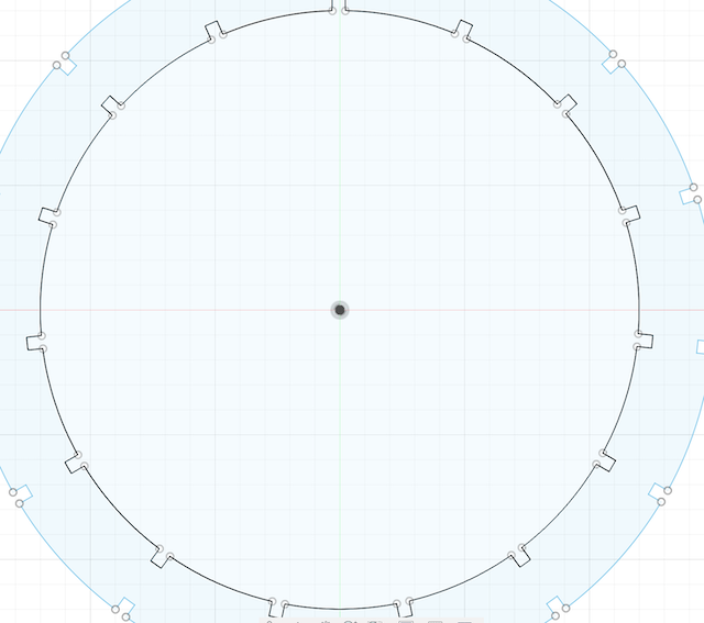
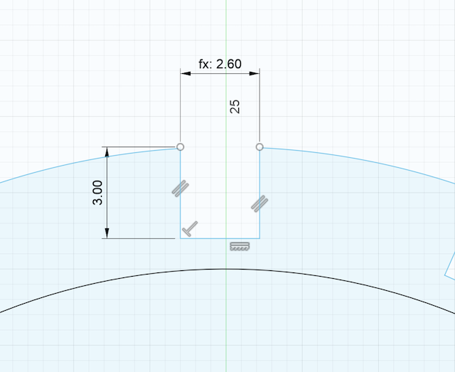
Step 10
Adjusted all measurements with my parameters (Thickness-KERF).
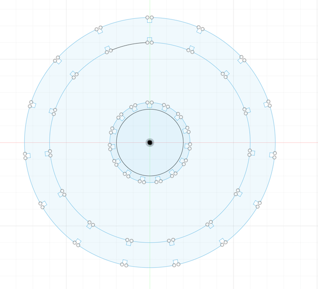
Step 11
With the base parts ready, I moved on to the interior part of the center, which will support the other pieces.
Step 12
First, I created a new sketch and basically repeated the previous steps with different measurements, adapting them to the parametric measurements.
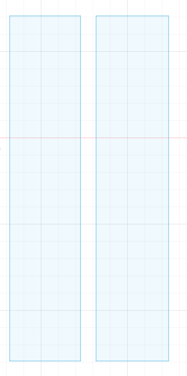
Step 13
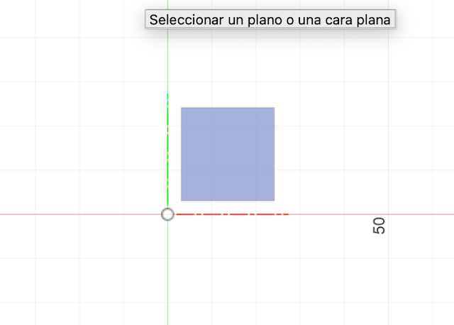
With these two pieces, I started on the rectangular pieces, essentially adjusting the size to fit the previous components.
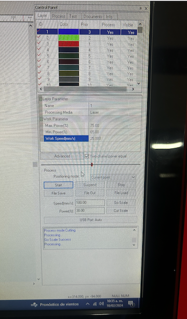
Step 14
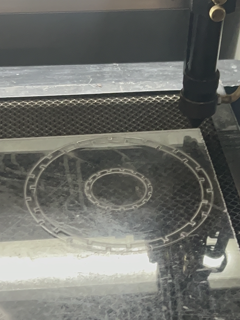
Once the pieces were ready, I sent them for laser cutting.Adjust the cutting speed parameters for the laser cutting machine, on which I sent my piece to cut 0, which would be the first one to see if my design worked.
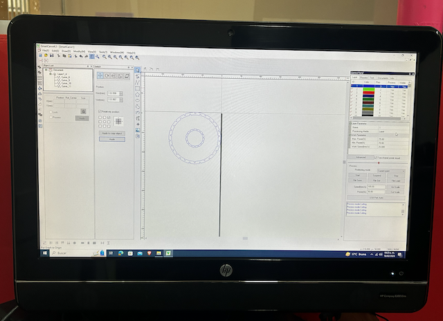
Step 15
I conducted various tests of laser cutting until finding the one that fit perfectly.
 /Users/valeriaarellanoyanez/Downloads/CONSTRUCTION KIT.f3d
Step 16
And there you have it, my construction kit is ready.
 8.14.08 a.m..png)
 8.14.18 a.m..png)
 8.14.36 a.m..png)
 8.14.49 a.m..png)
 8.14.57 a.m..png)
What I learned
During my experimentation with various KERF measures, I embarked on a fascinating journey of discovery, grappling with the variability of the material at hand. From a thickness of .1 to .4, I explored a wide range of possibilities to determine the optimal measure that would adapt to the ever-changing characteristics of my material. The diversity in the thickness of my material presented intriguing challenges but also opportunities to learn and refine my skills. As I experimented with different KERF measures, I observed how the cutting and engraving process uniquely responded to each variation in thickness. Although this path involved some material wastage, each trial and error became another rung on my ladder towards mastering the subject. Finally, after countless trials, I identified that the most effective KERF measure for my specific project was .22. This revelation not only marked the success of my effort and dedication but also the tangible manifestation of the fruits of perseverance. Despite the initial material wastage, each failed attempt transformed into a valuable lesson, guiding me towards a deeper and more practical understanding of the subject. In summary, my experience of trial and error with various KERF measures was not just a technical exercise but a learning journey that allowed me not only to attain the necessary practical knowledge but also to appreciate the intrinsic value of perseverance and experimentation in the creative process.
Team Practice
Here its the link of our team practice.
My interest in personalized design led me to the fascinating world of laser cutting. After studying its fundamentals, including the crucial concept of "kerf" (cutting width), I decided to apply this knowledge to my own project: a unique table lamp. I carefully selected the material, considering its suitability for laser cutting and the required transparency. While designing the lamp, I adjusted the dimensions, taking into account the kerf to ensure a perfect fit for each piece. During the cutting process, I witnessed the astonishing precision of laser technology. Although I faced challenges adjusting the kerf to perfect the cuts, each mistake became a valuable lesson. The end result was a table lamp that illuminated not only my space but also my appreciation for the blend of laser cutting theory and creative practice. This project underscored the importance of experimentation and dedication to transform knowledge into practical skills.
Computer controlled Cutting - Vinyl
Here its my Computer controlled Cutting design process of my vinyl .
Step 1
I used a program called Curve, which basically does the same thing as Illustrator.

Step 2
Within the program, I opened a new sheet.
Step 3
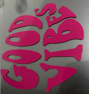
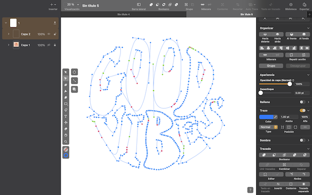
There, I started drawing the text of my sticker using the curve tool.

Step 4
I edited it with the vector points until I achieved the desired image.
Step 5
I exported it as a PNG.


Step 6
I downloaded the Silhouette Studio program for the vinyl cutter.

Step 7
I opened my PNG image in the program.
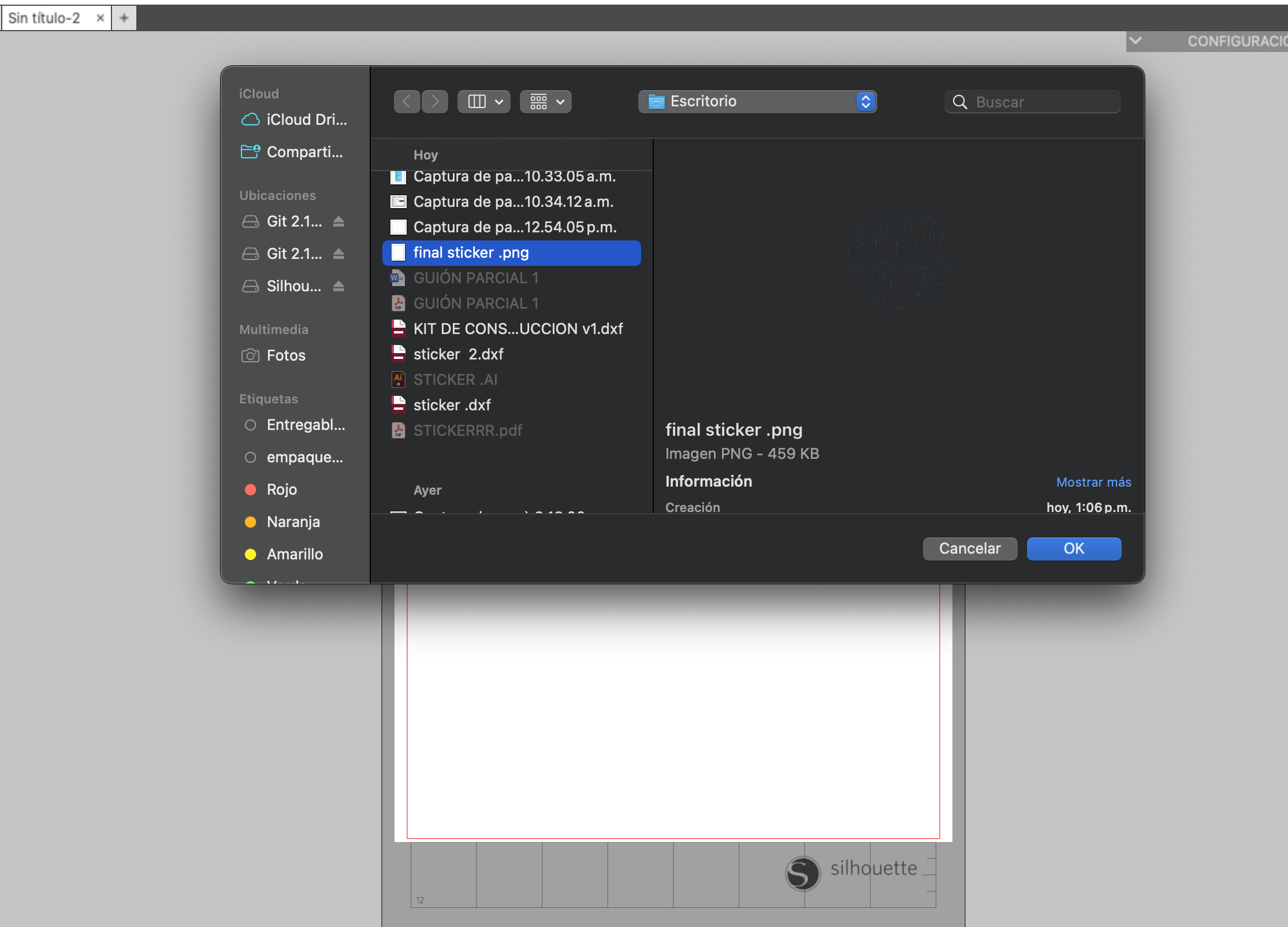
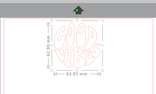
Step 8
I arranged it on the sheet and gave it a specific size.
Step 9
I placed my vinyl on the special sheet for the machine and positioned it correctly.
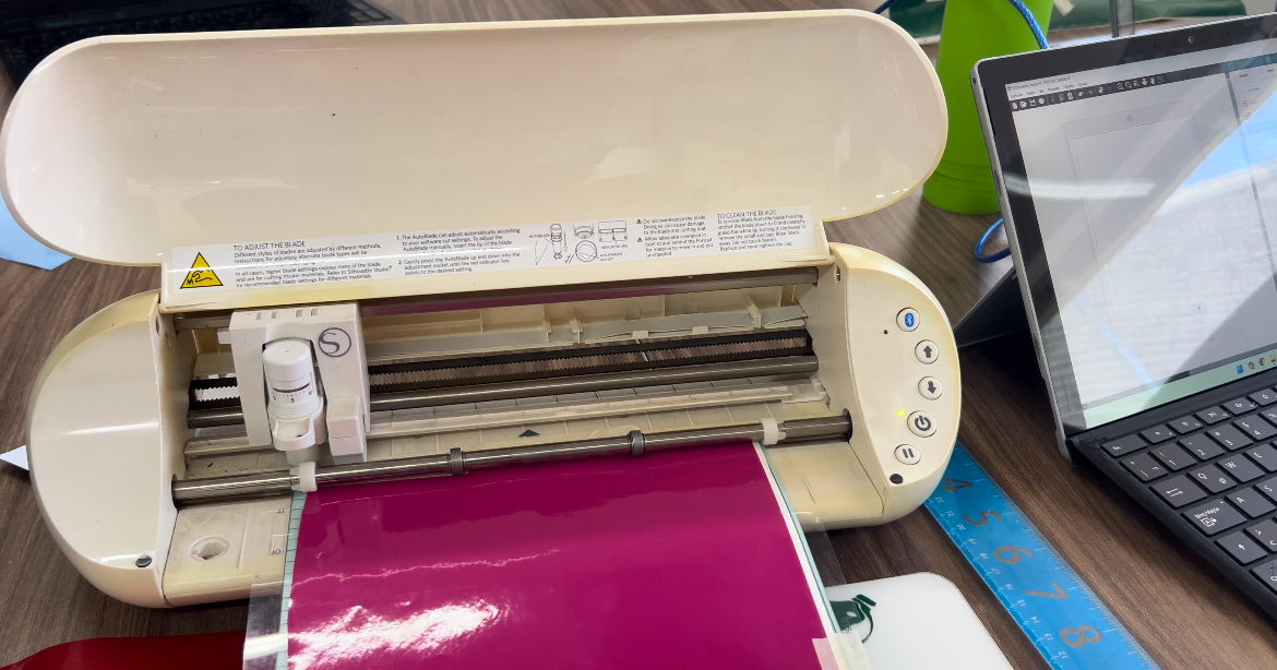
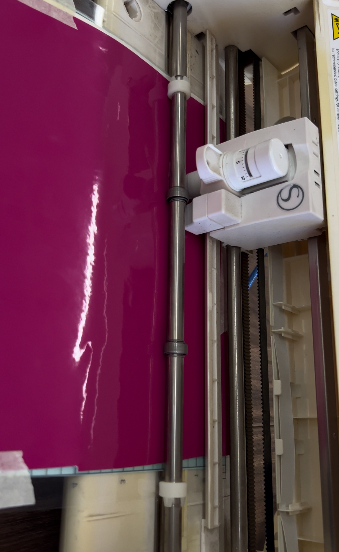
Step 10
I sent my sticker to be cut.
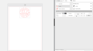
Step 11
The program cut my vinyl, and I removed the cutting sheet.
Step 12
I carefully peeled off my sticker and placed it on the back of my laptop.