5. 3D Scanning and printing
First of all, in our group webpage, we explain about 3D printing technology and materials. Here, you can find the IMPORTANT RULES about design and support. And we show and explain the characteristics of each 3D printers which have in FABLAB Puebla. Please ensure to verify your model and its characteristics.
3D Printing
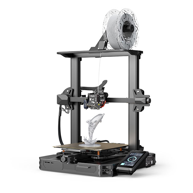
For my individual assignment I use this machine: Ender 3 S1 PRO.
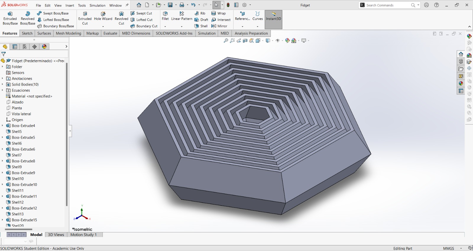
Briefly, I will explain the design. I created a hexagon and parametrized it to easily generate the subsequent hexagons that make up the piece.
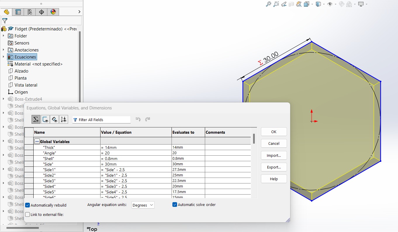
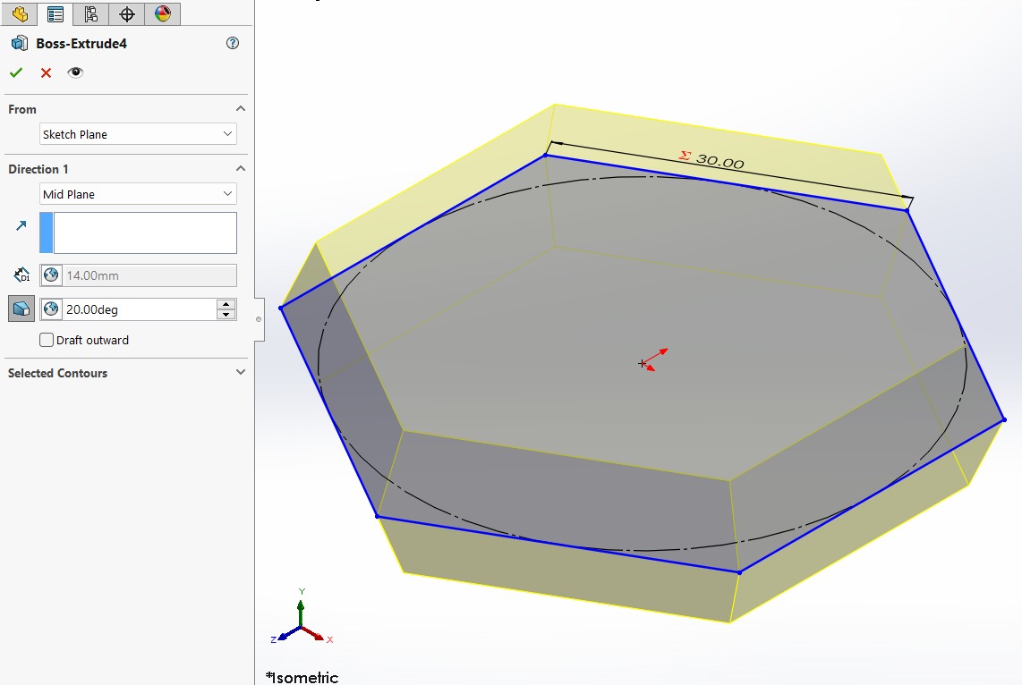
I extruded the solid at an angle of 20° to 30°; this is important since it allows joining all the pieces into one, which cannot be achieved with subtractive methods.
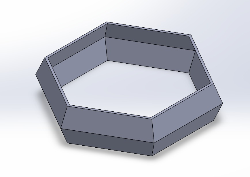
Next, I hollowed out the solid using the shell operation.
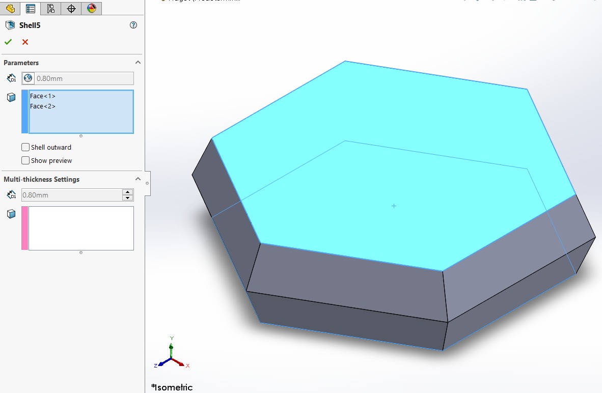
We now have our first ring.
I proceeded to repeat the same process for all the pieces in our design. You can find the CatPart and STL files below in the Files section.
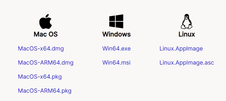
Then download (click here) Ultimaker Cura software from this link
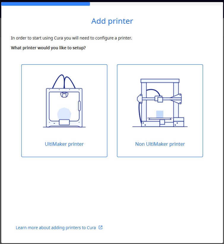
Open Cura and configure it.

First, choose a non-Ultimaker printer.
Then, add a networked printer and choose your 3D Printer. At FabLAB Puebla, we have Ender 3 S1 Pro.
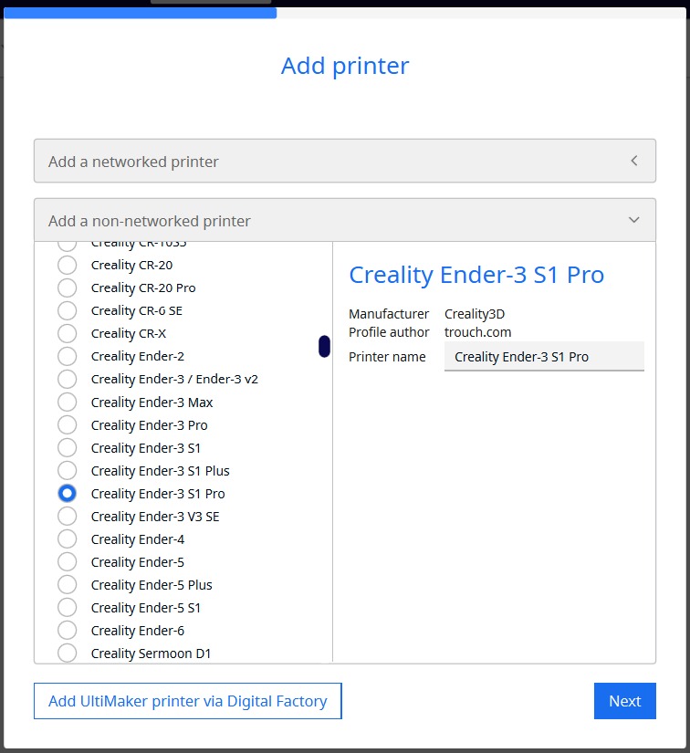
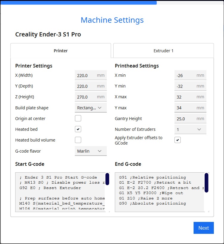
Finally, in Machine Settings click on next, because we'll use the default settings.
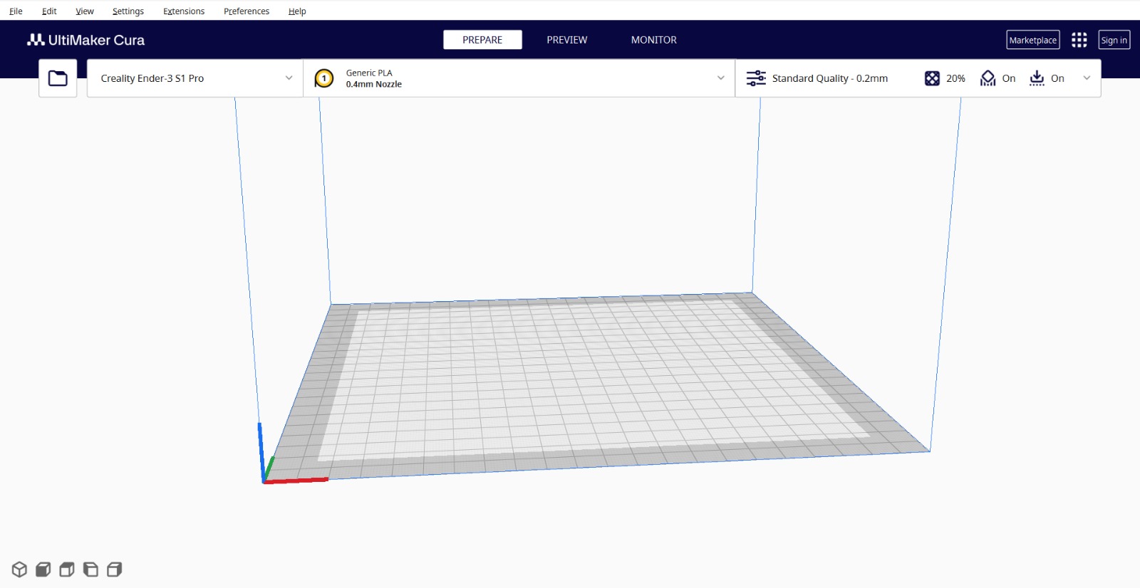
This is the Cura interface.
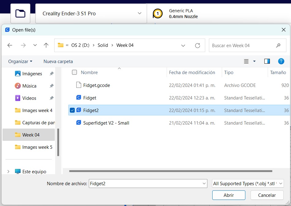
Click on the folder icon and select your file.
You will see something like this.
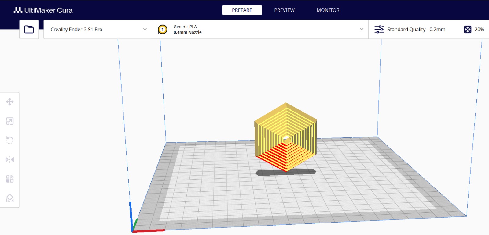
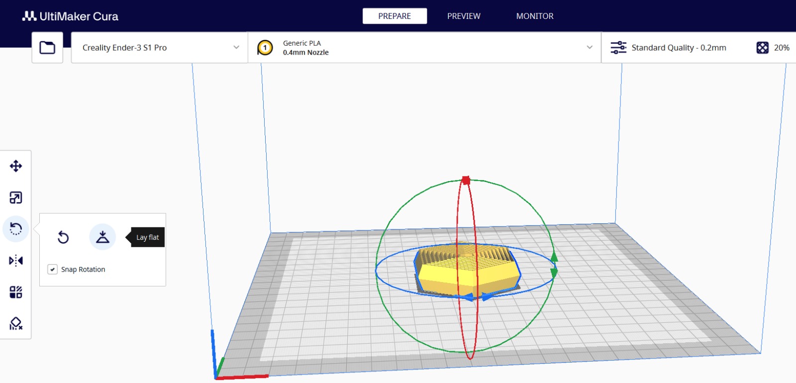
The piece must be completely on the surface to avoid mistakes or use too much material for the supports. Therefore, you need to select the piece and use the rotate option to drag square knots along with the "Lay Flat" option. In the same panel, where we have the option to rotate, we find more features, such as: moving the piece, scaling it, mirroring it, among others.
In the upper right corner you will see this tab, click on it.
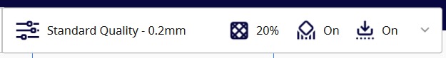
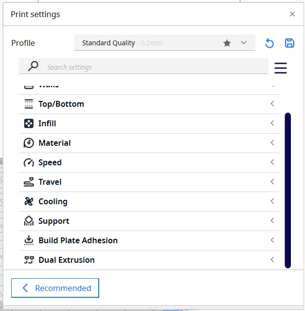
This is the settings interface. Here are the basics
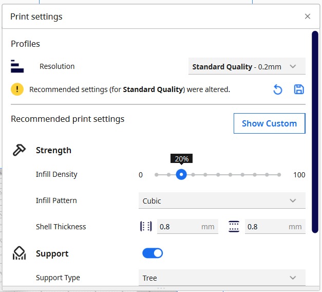
But we are pros and choose show custom.
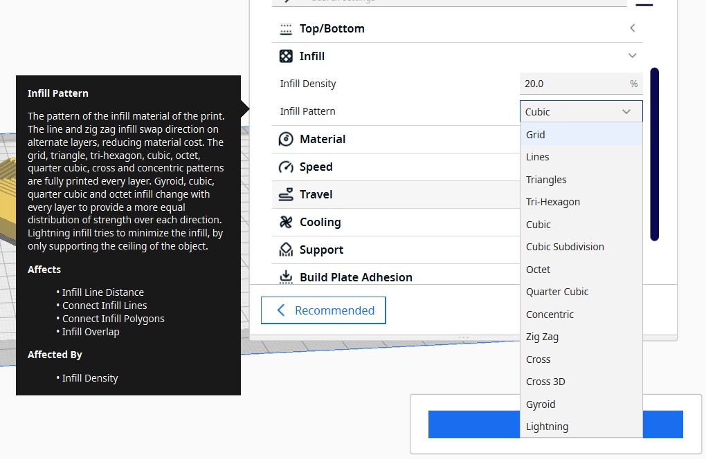
The configuration I used was a cubic infill of 20%. There are many options for each design. You can find this explanation on our group webpage.
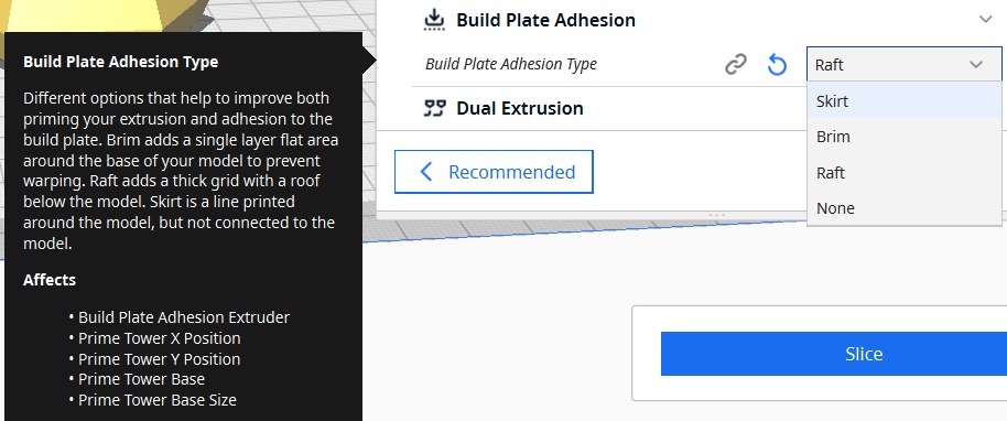
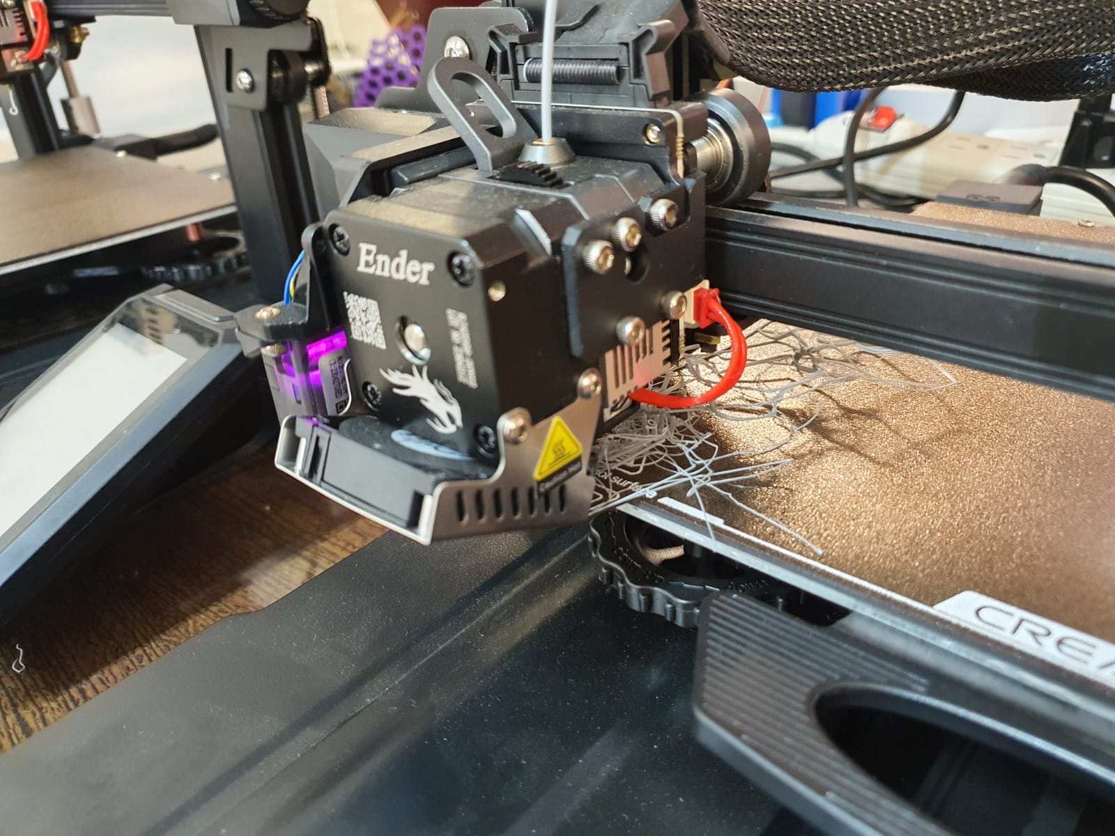
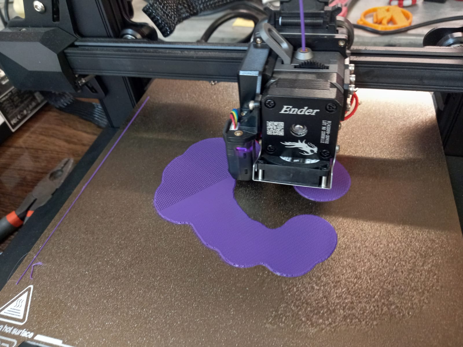
And don't forget to choose a build plate adhesion. In my case, I use "Raft" because you ensure that the print will not warp or become spaghetti. Although it uses a greater amount of material.
Otherwise, your print will fail. Like this
After, you configure your piece, click on "Slice".
The time, weight and material to be used will be displayed.
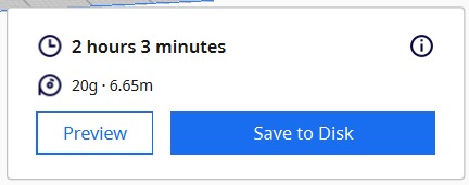
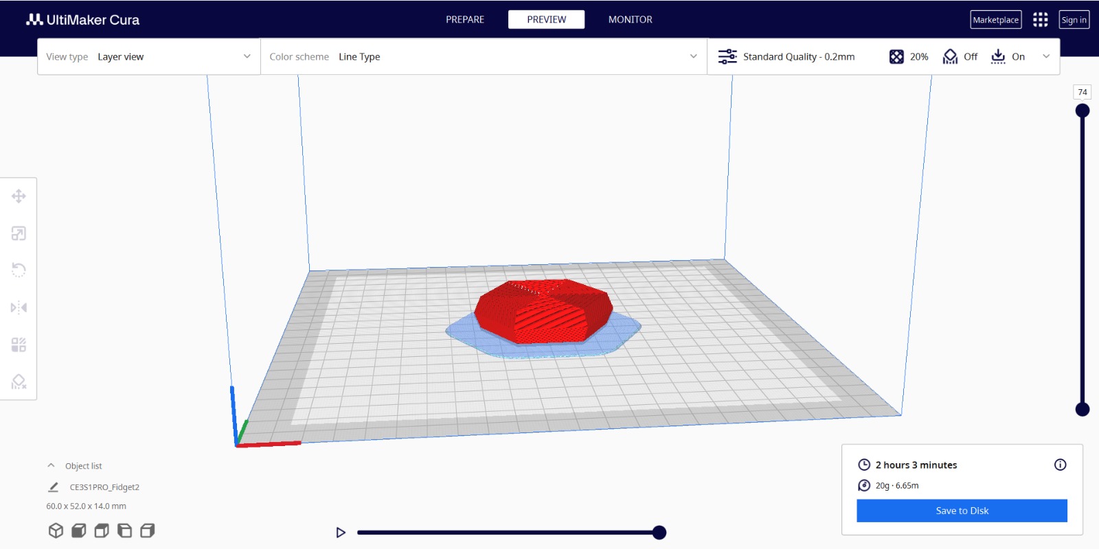
Select Preview to see that everything is as planned and if it so, save it to your disk.
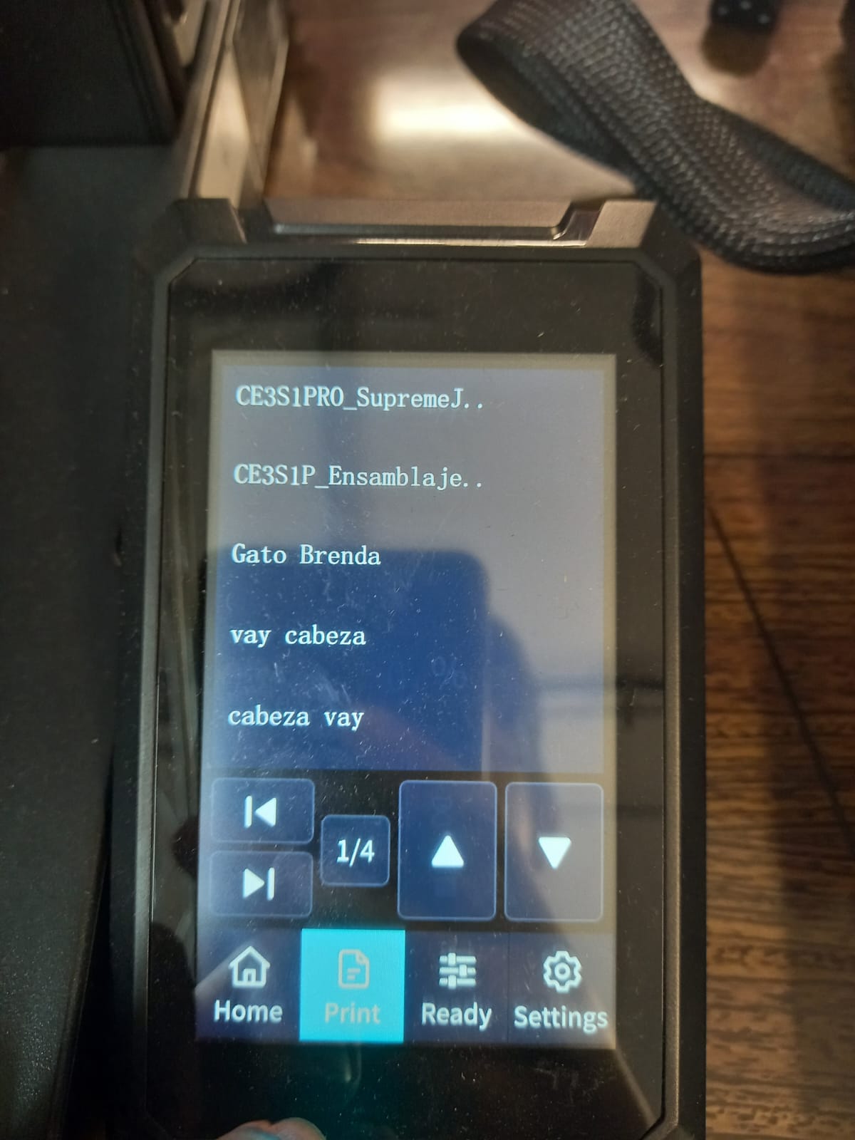
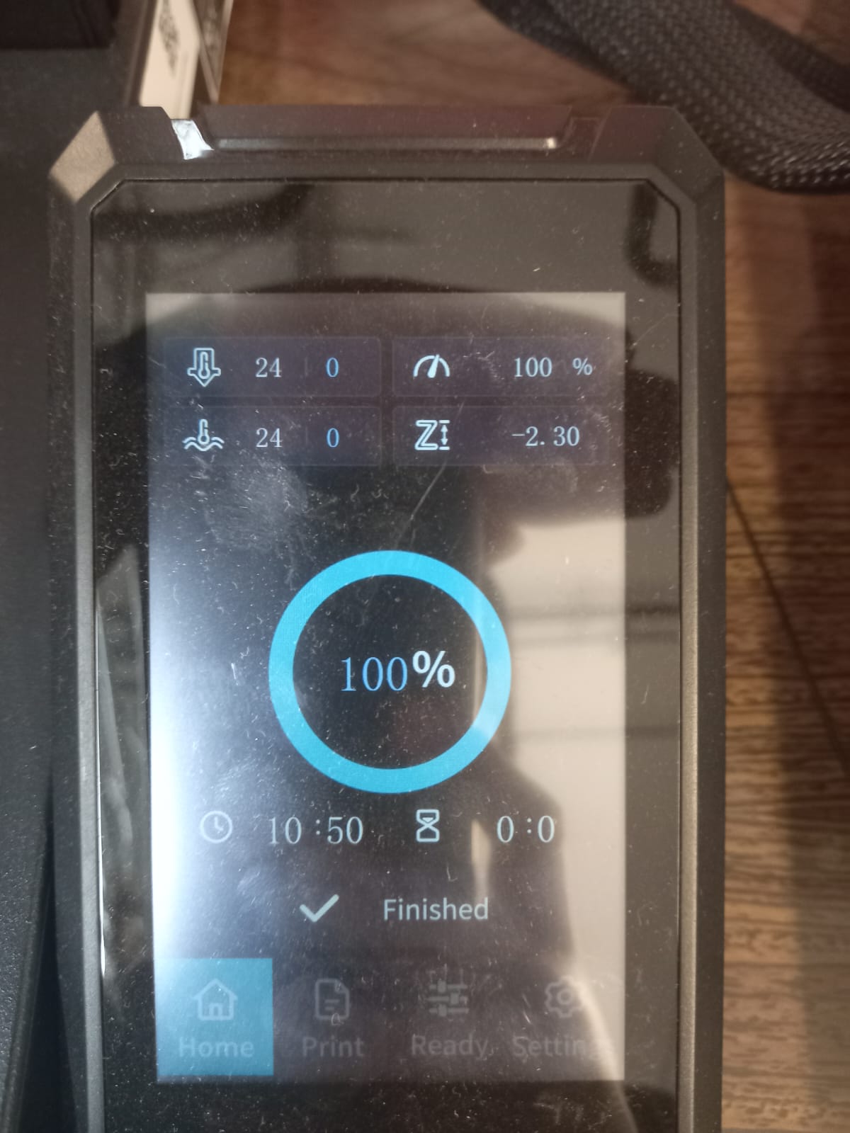
Put your removable media in your 3D printer. This is the interface of the Ender 3 printer.
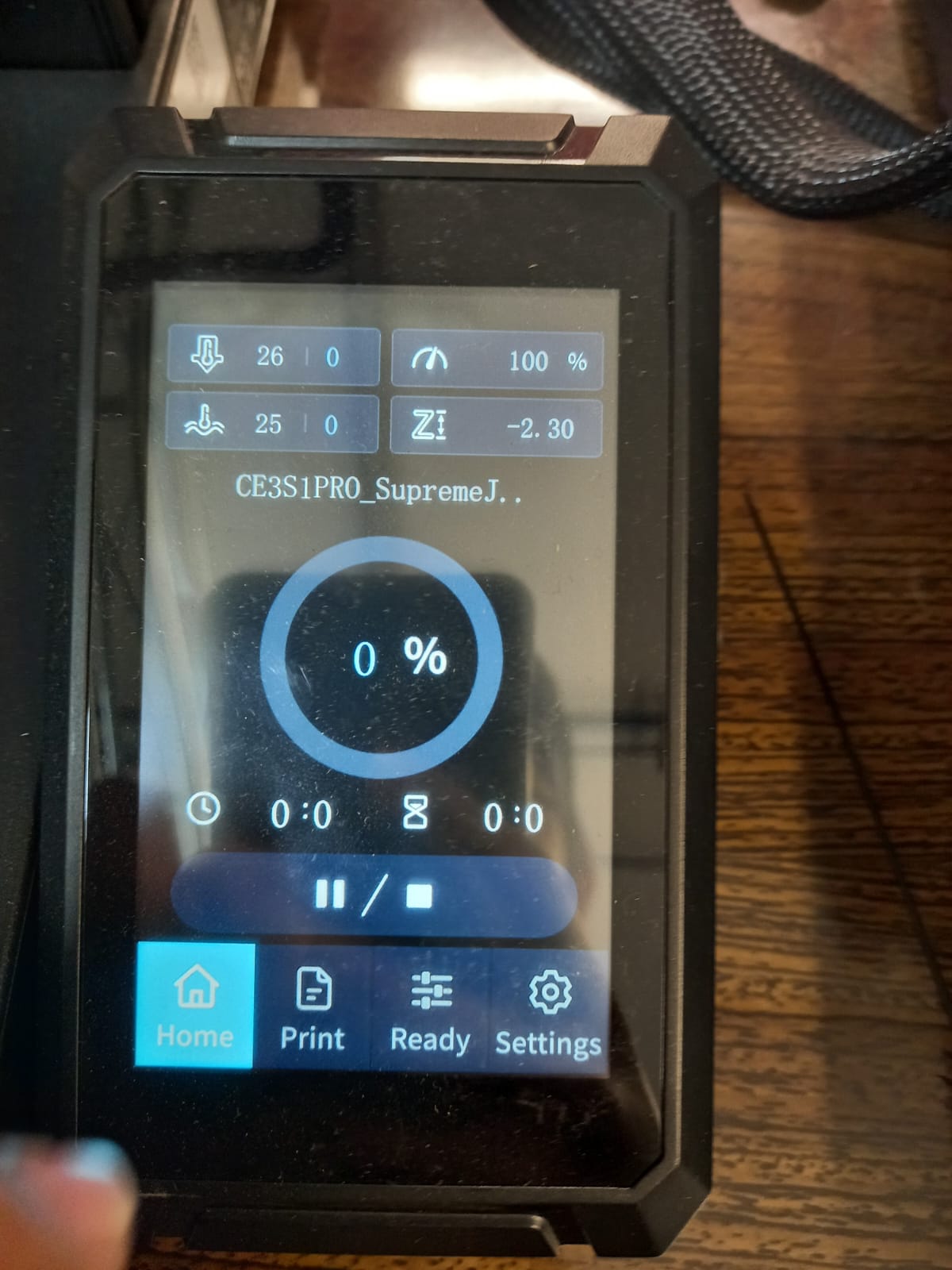
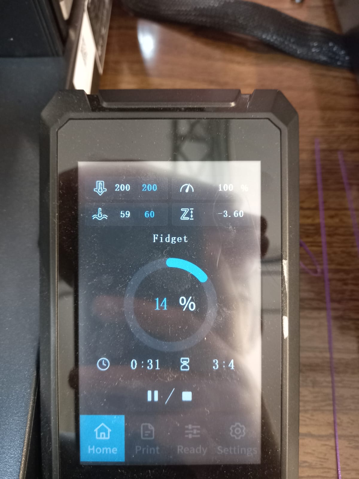
Make sure nozzle and bed temperature are 190-220°C and 50°C-70°C respectively. My choice was nozzle 200 °C and bed 5°C, these configurations are in "ready" option. Select print and your file.
Finally, select the play/pause ( > / || ) button.
The 3D print process gallery
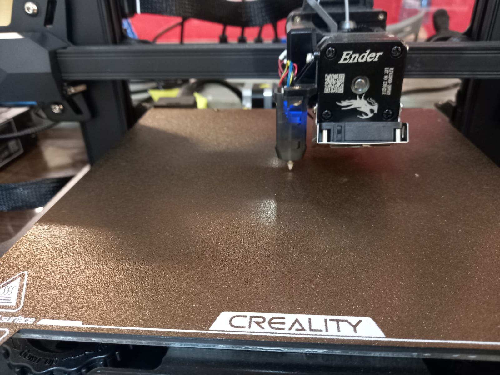
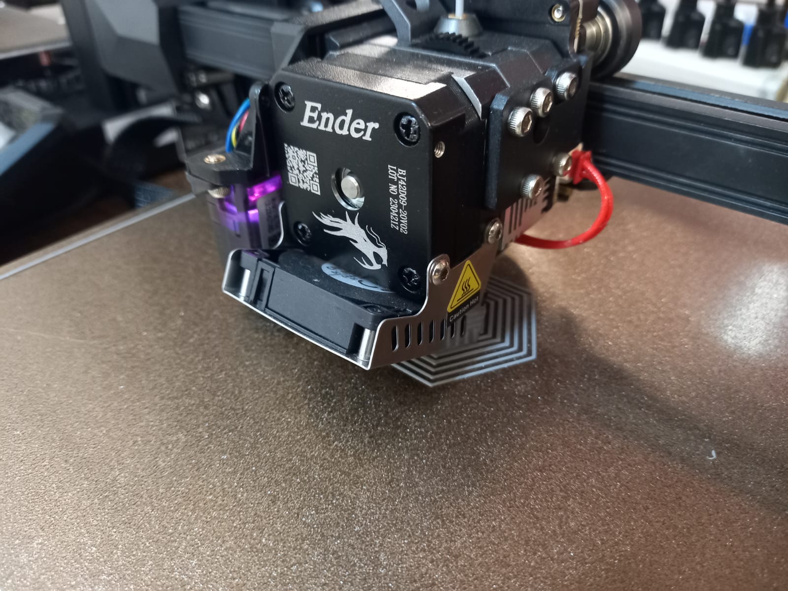
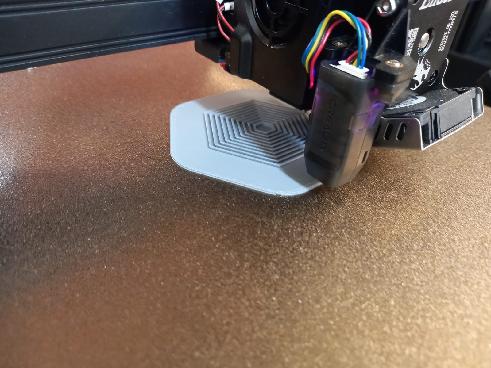
This is really COOL!
3D Scanning
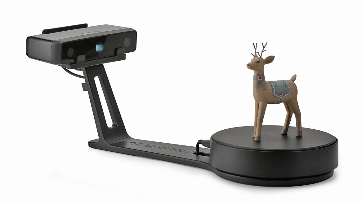
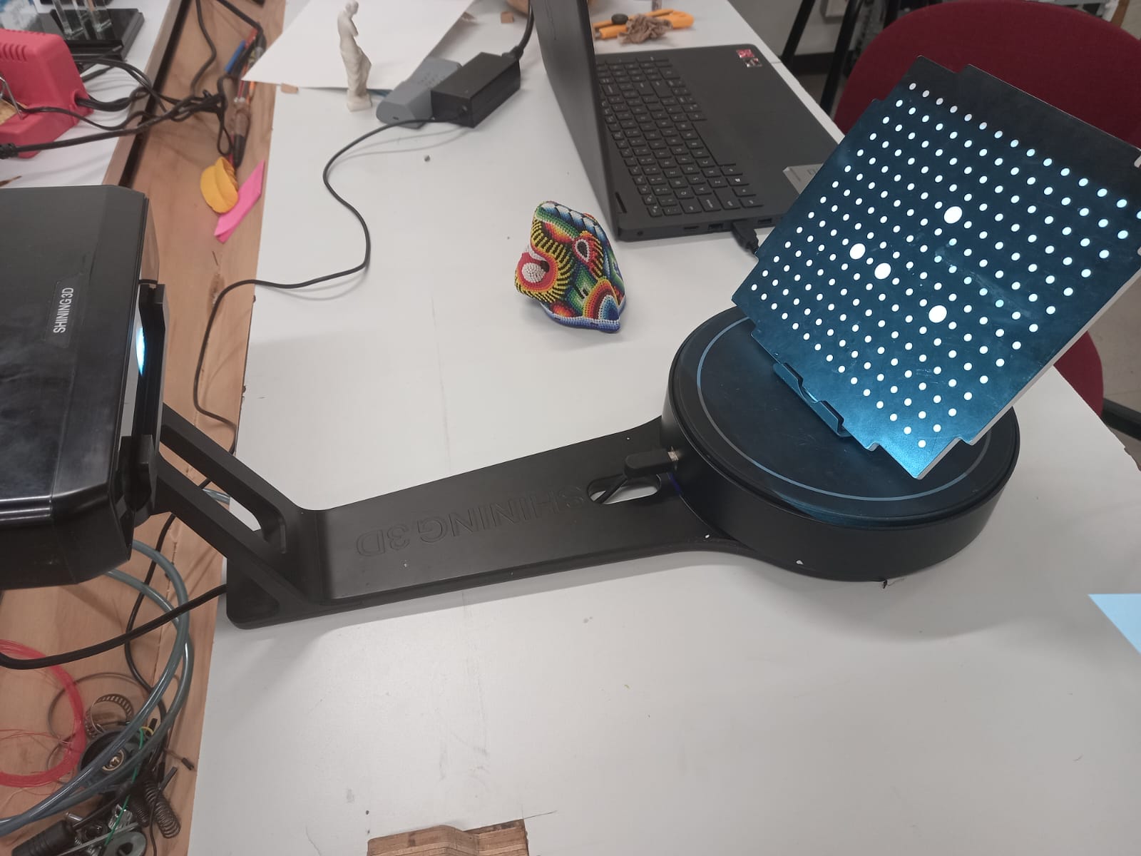
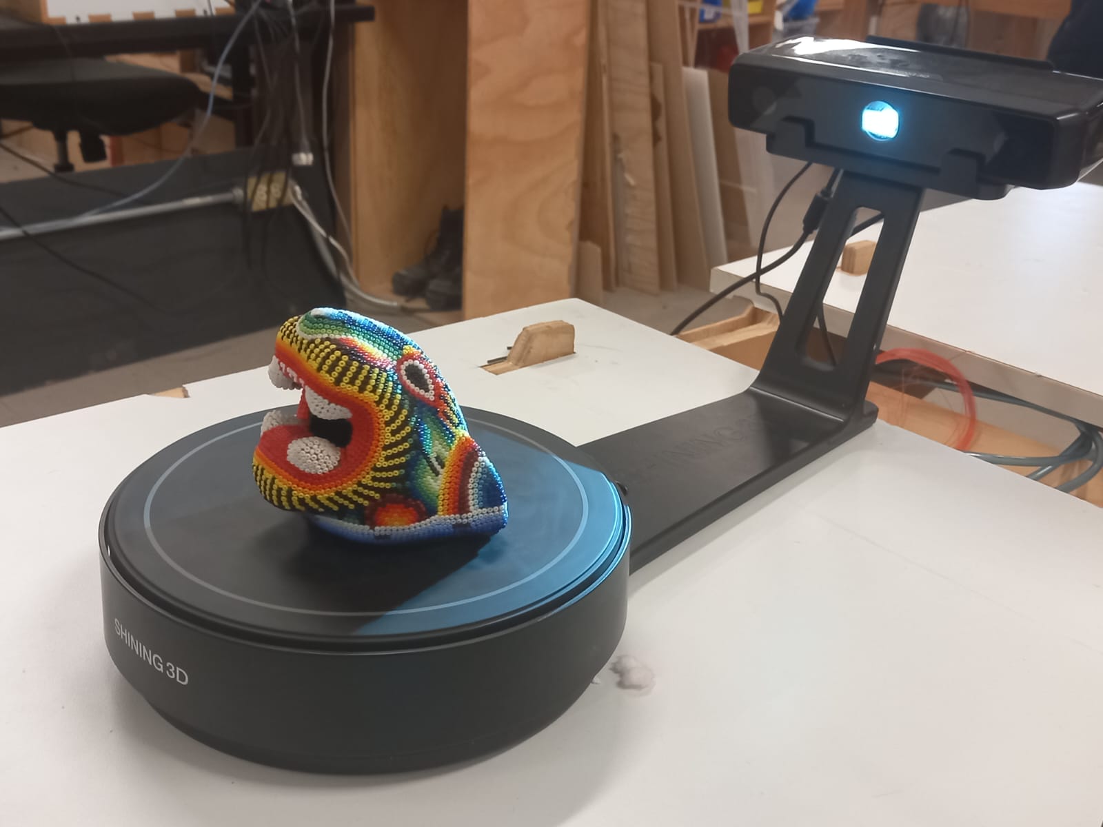
Our fablab uses this machine: REinscan SE V2
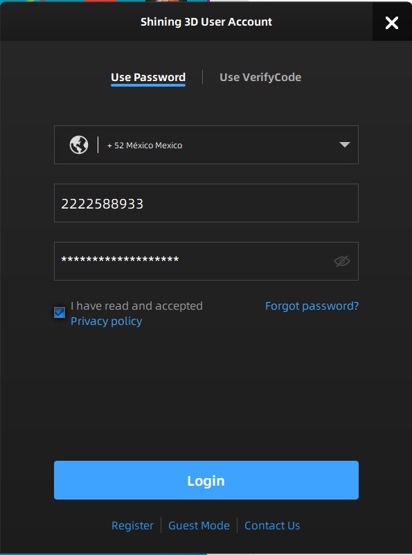
Click on this link to download EXScan software
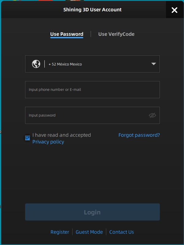
Install it and create an account.
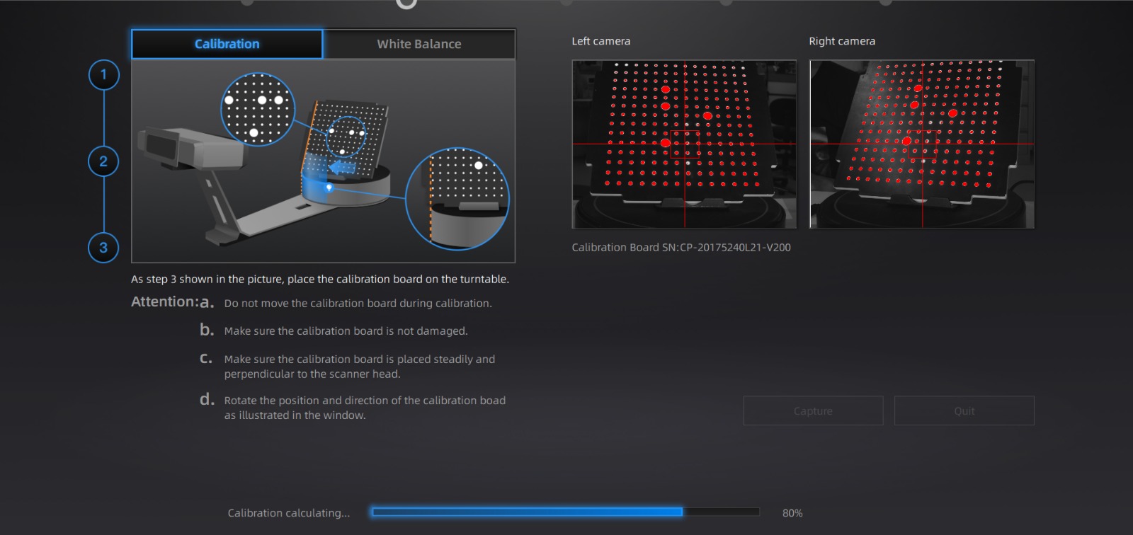
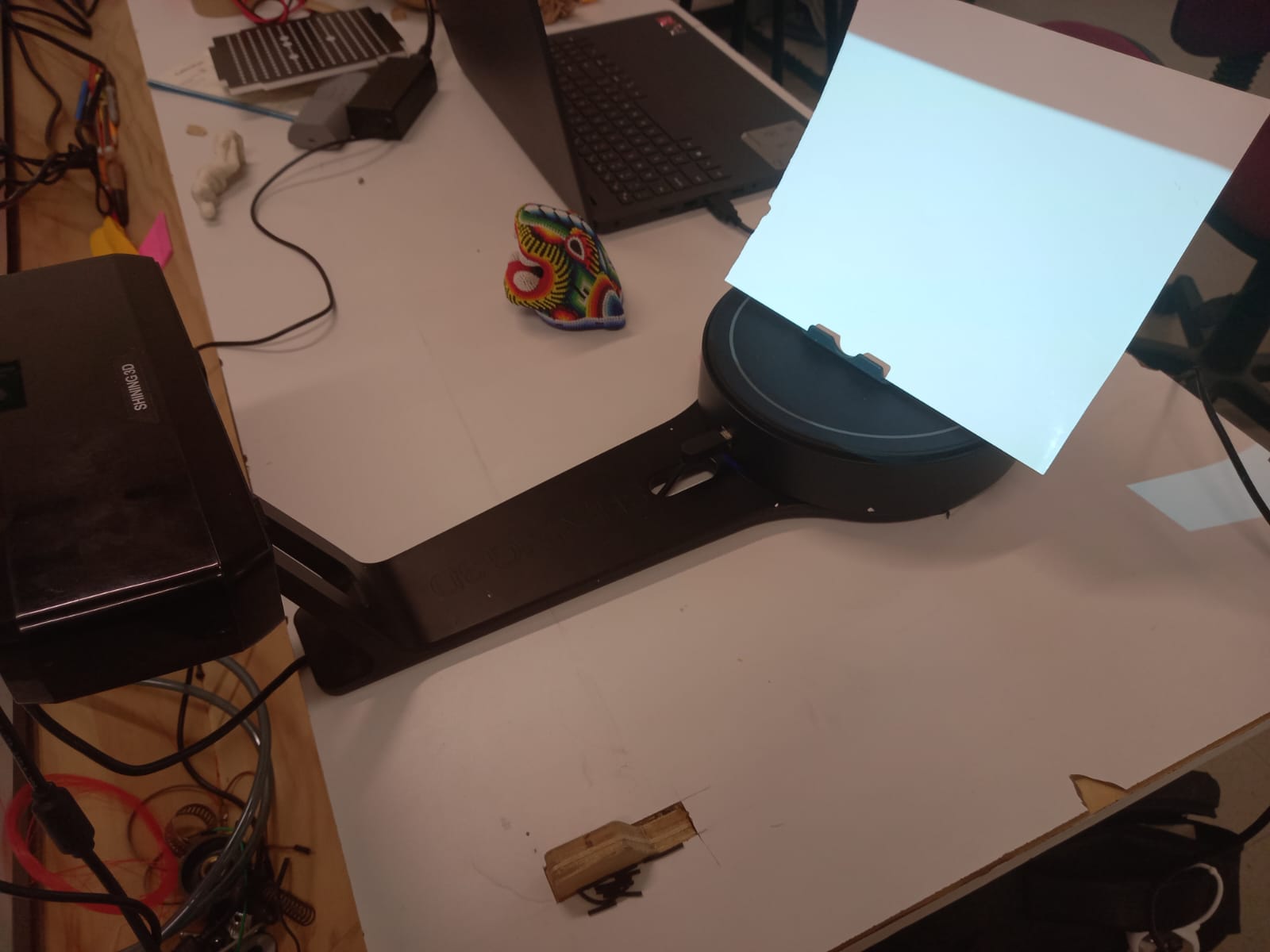
After connecting and turning on the scanner. Calibrate the machine following the instructions. We can notice that the white points are marked red. Remember this*.
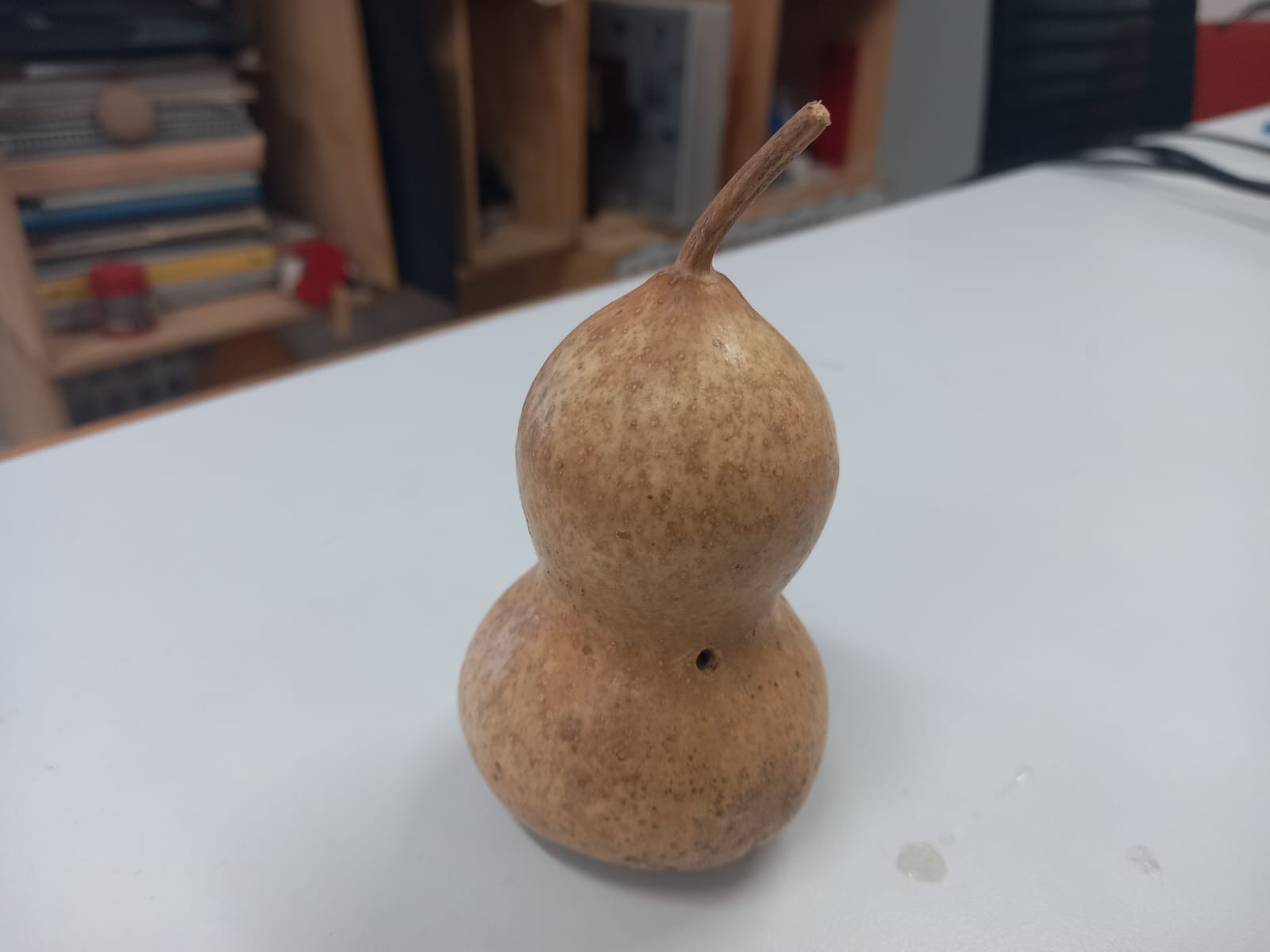
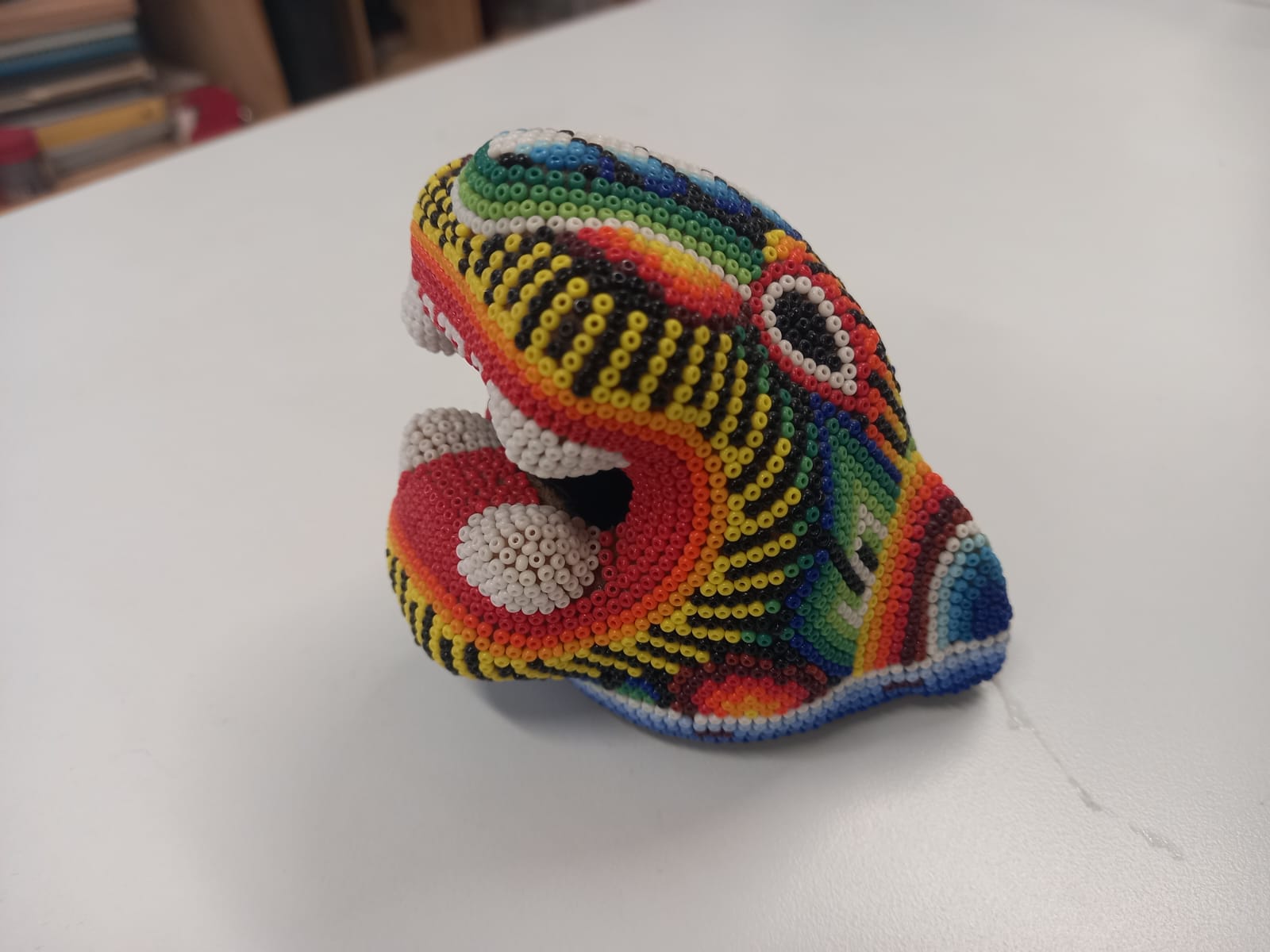
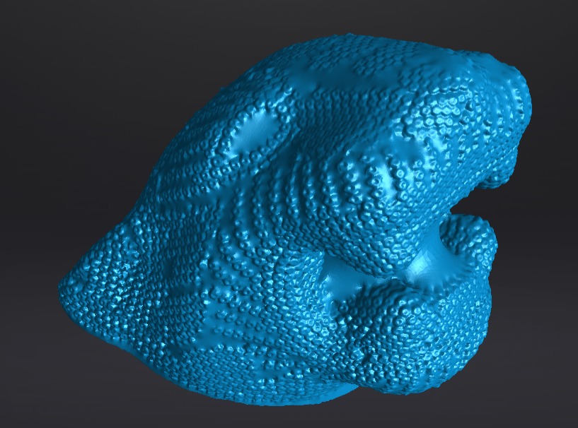
I will use this models for this assignment. Because, I want to see how well scanning.
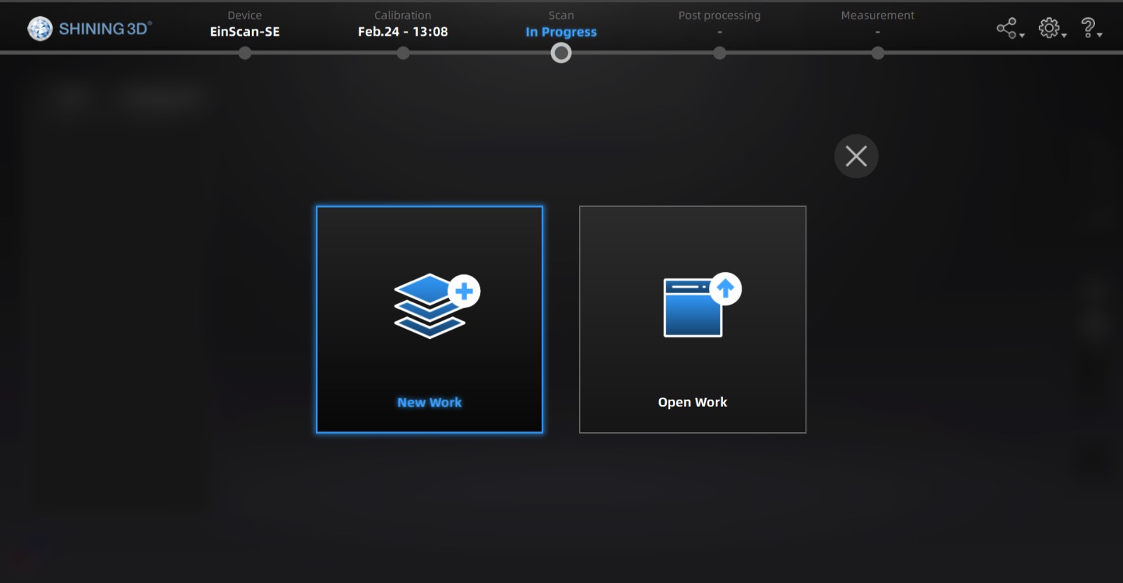
Open a new work
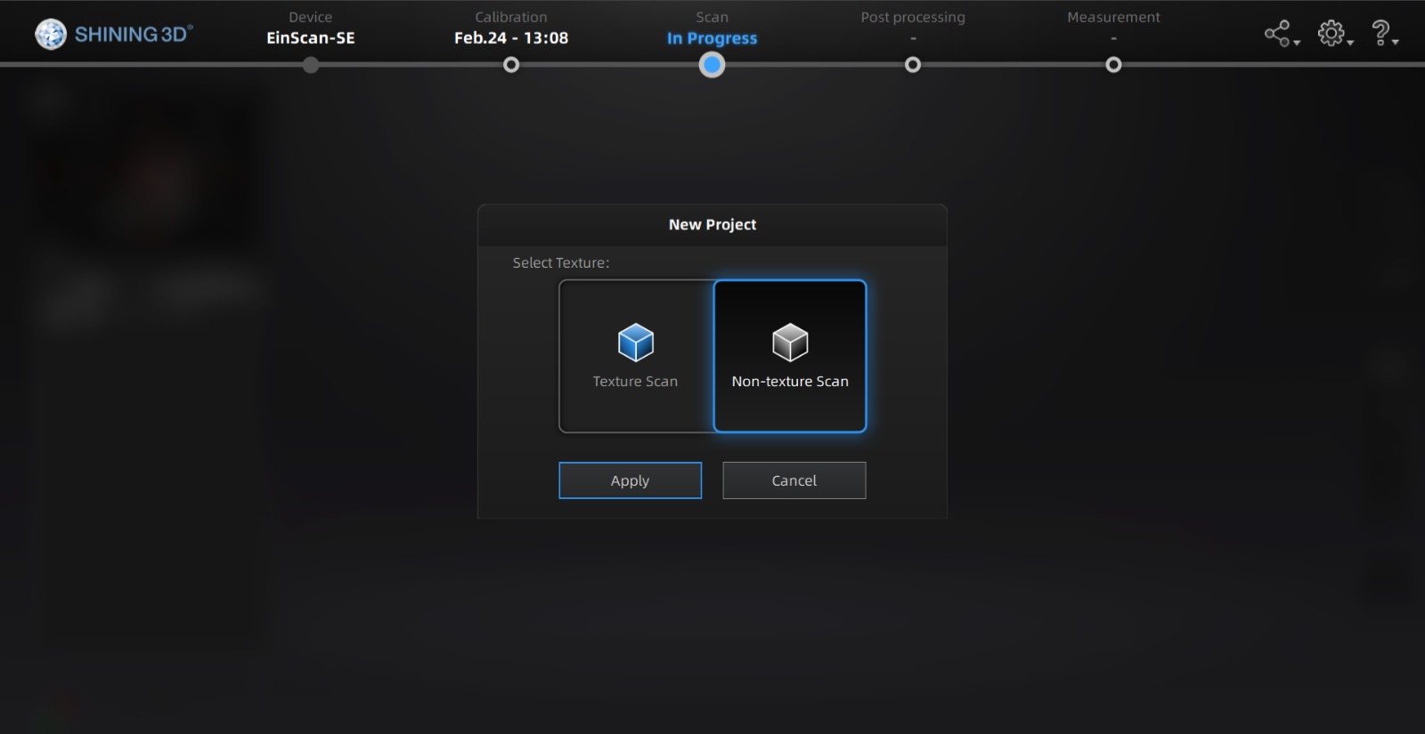
And select non-texture scan, because we don't want to scan colors for now.
This is the Shining 3D interface.
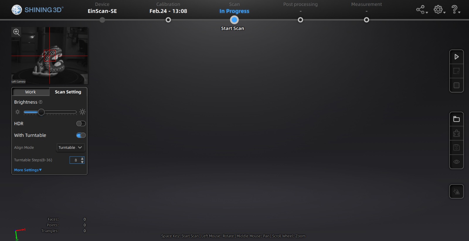
IMPORTANT: If your object isn't symmetrical, select Align Mode 'Features' on the Scan setting tab. 'Turnable' is the default option, and you will get something like this if it's ON.
Put your object in the middle of the platform scanner.
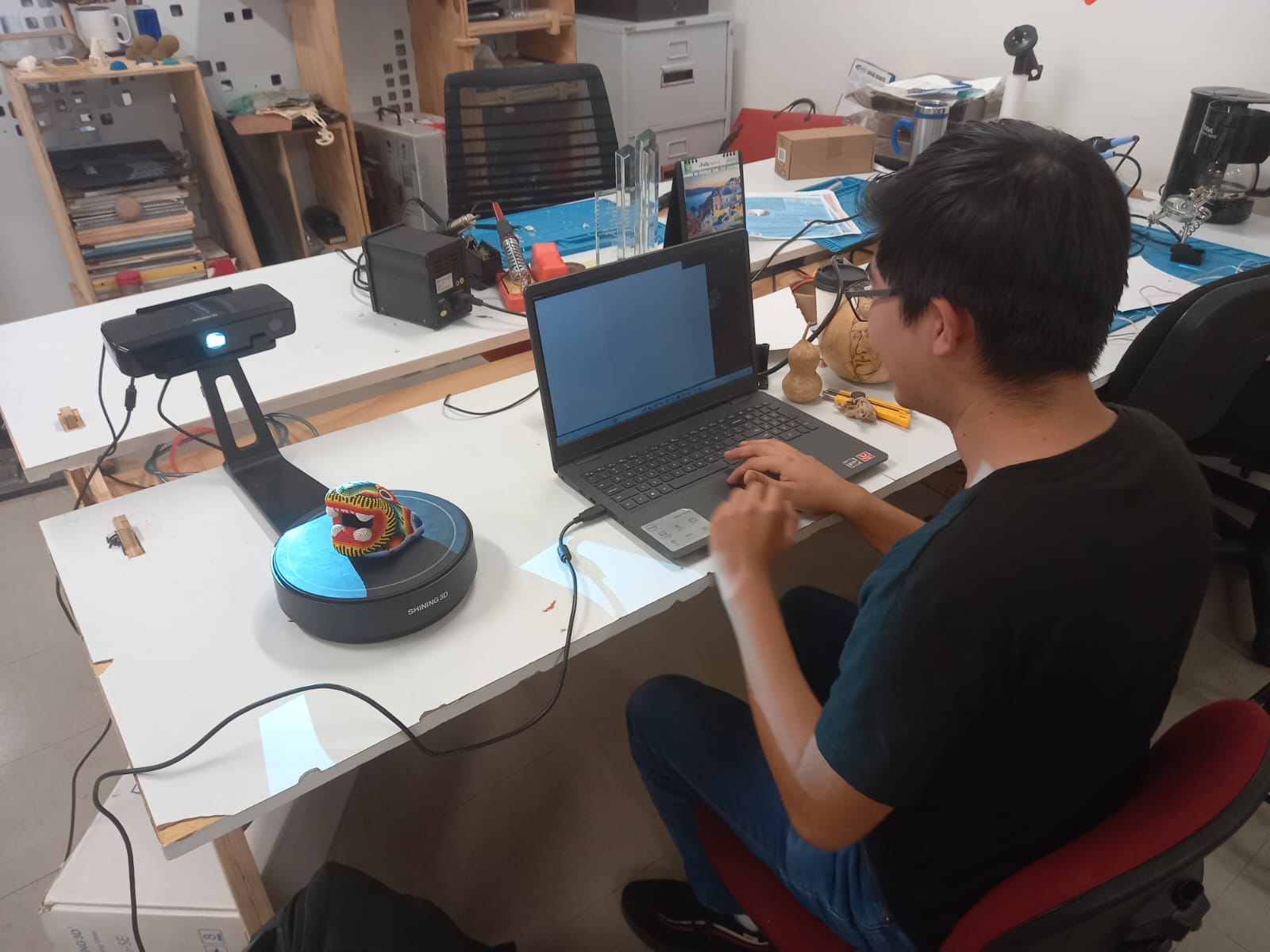
Click on start button to start scanning.

I set the following for my scan:
- Enough brightness to see red points*
- Align mode: Features
- Turntable Steps: 16
- Turnable Speed: 6
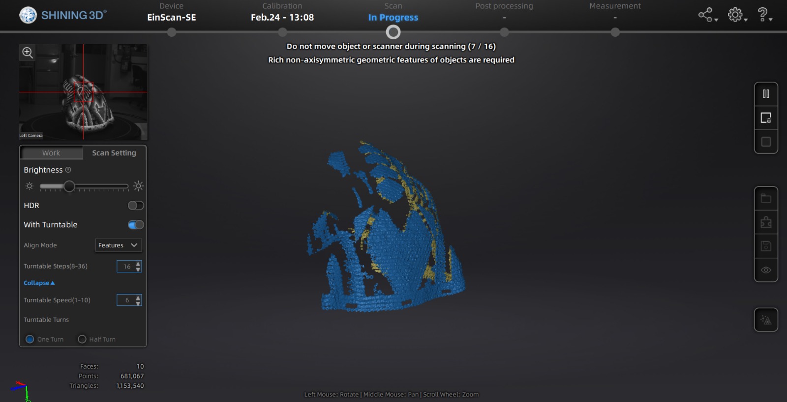
Here I didn't set the brightness correctly, make sure to see red points on the interface for the white surfaces, points, and objects.
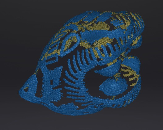
Much better!
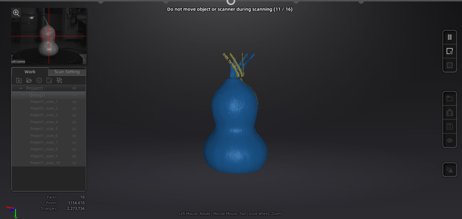
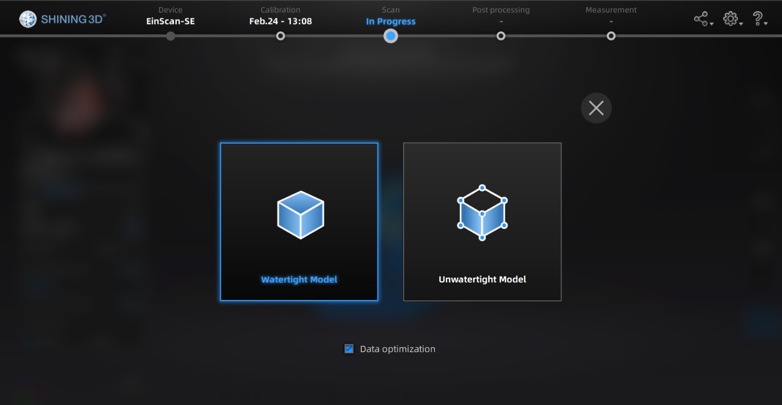
Then click on play button and mesh model
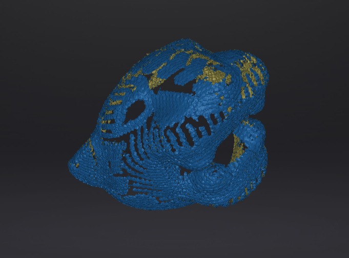
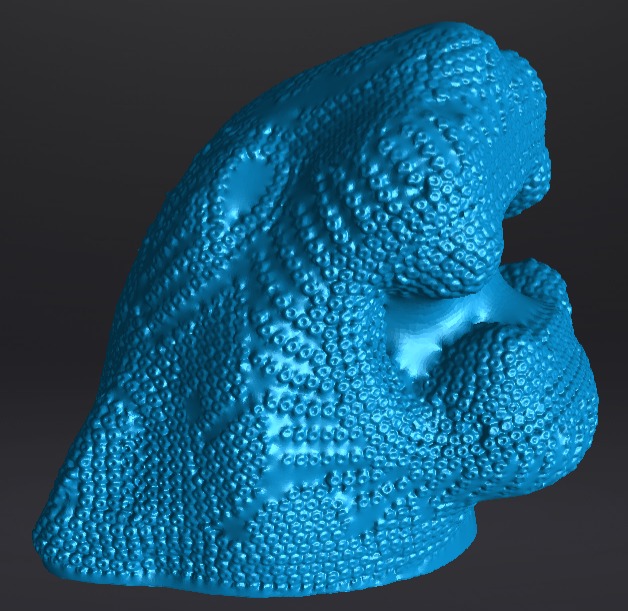
And select watertight model
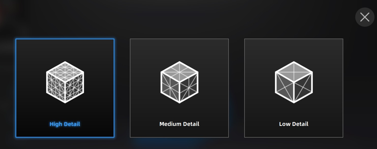
Depending on the definition you desire, choose the level of detail. In my case, I selected medium detail.
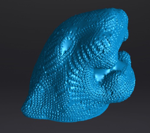
Looks awesome!
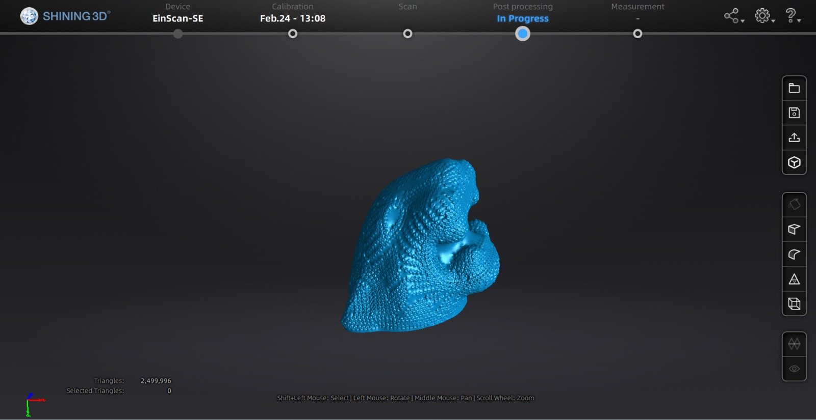
We are going to simplify with selecting simplification.
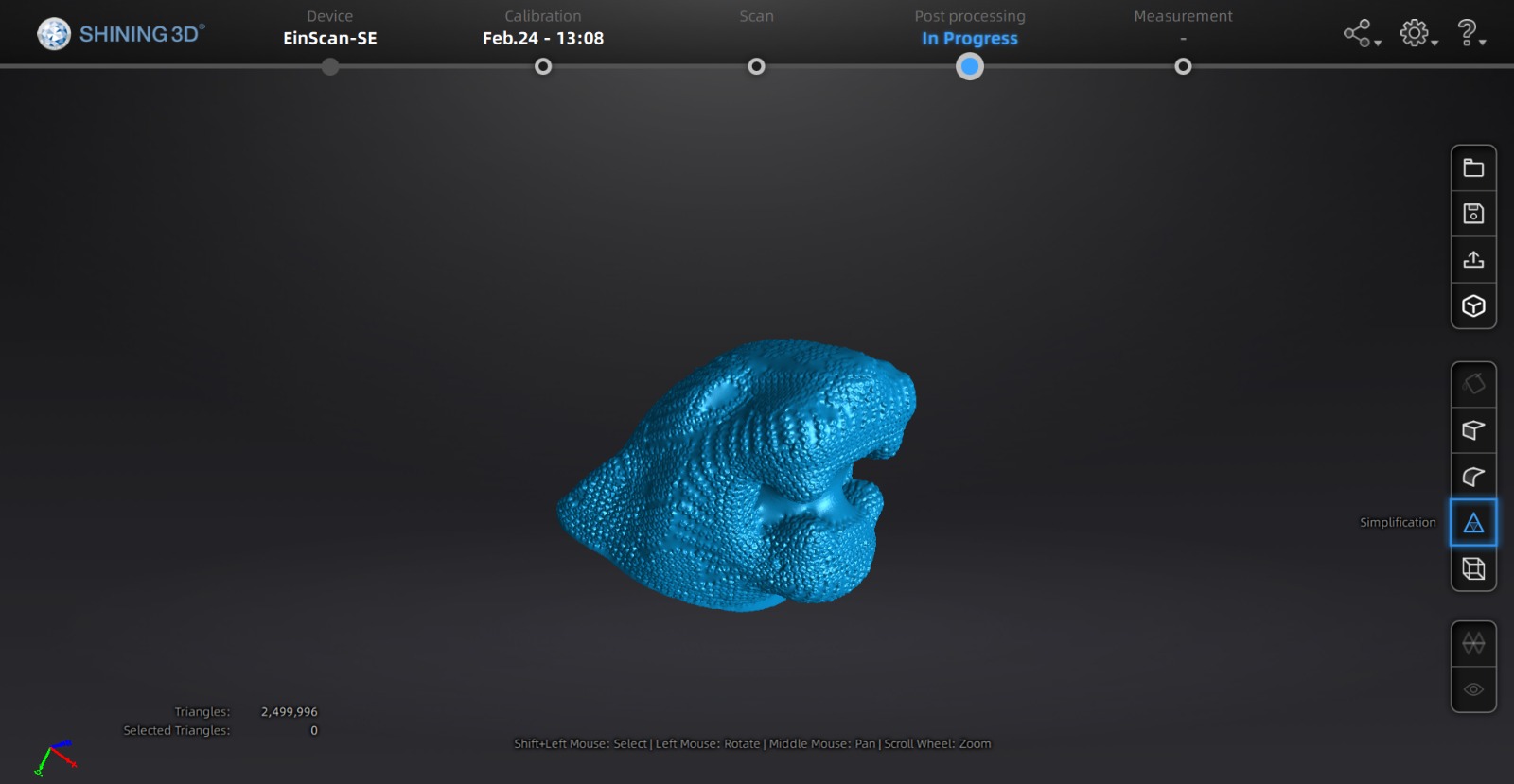
There are many triangles, which will be a problem when transferring it to an external program for 3D printing. Therefore, we simplified it to 10%.

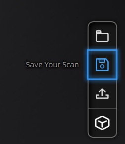
Finally, save your scan. Click on it.
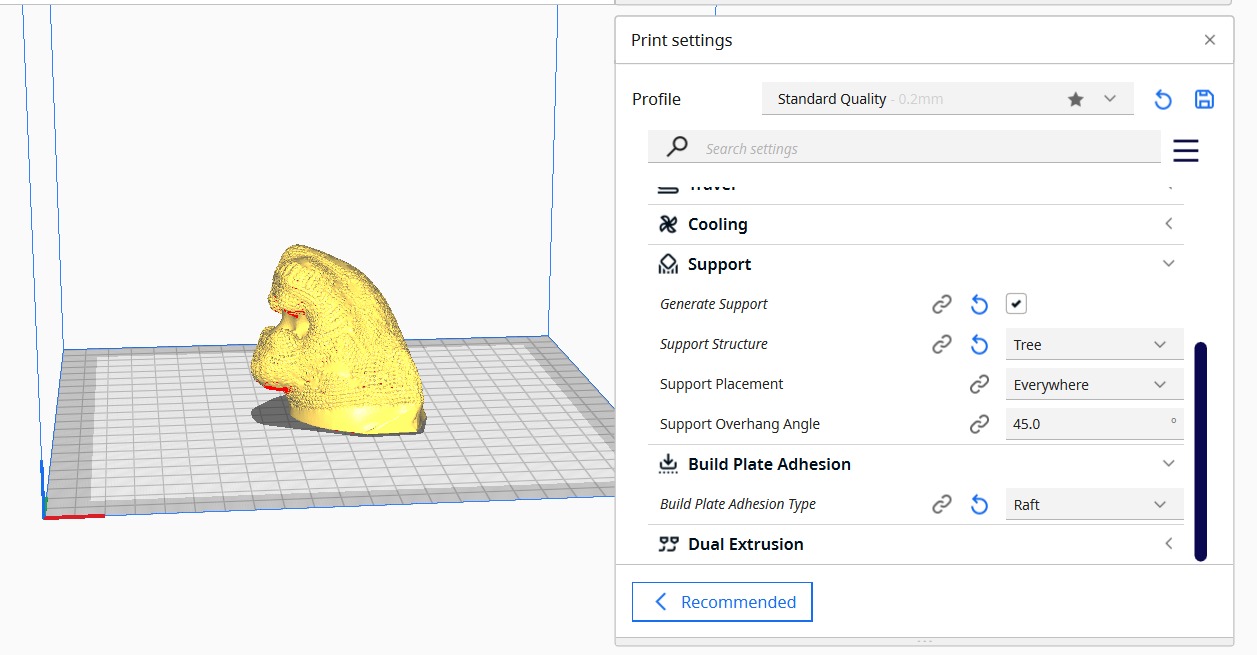
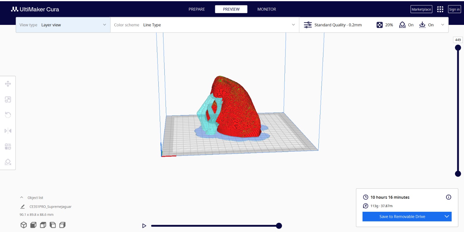
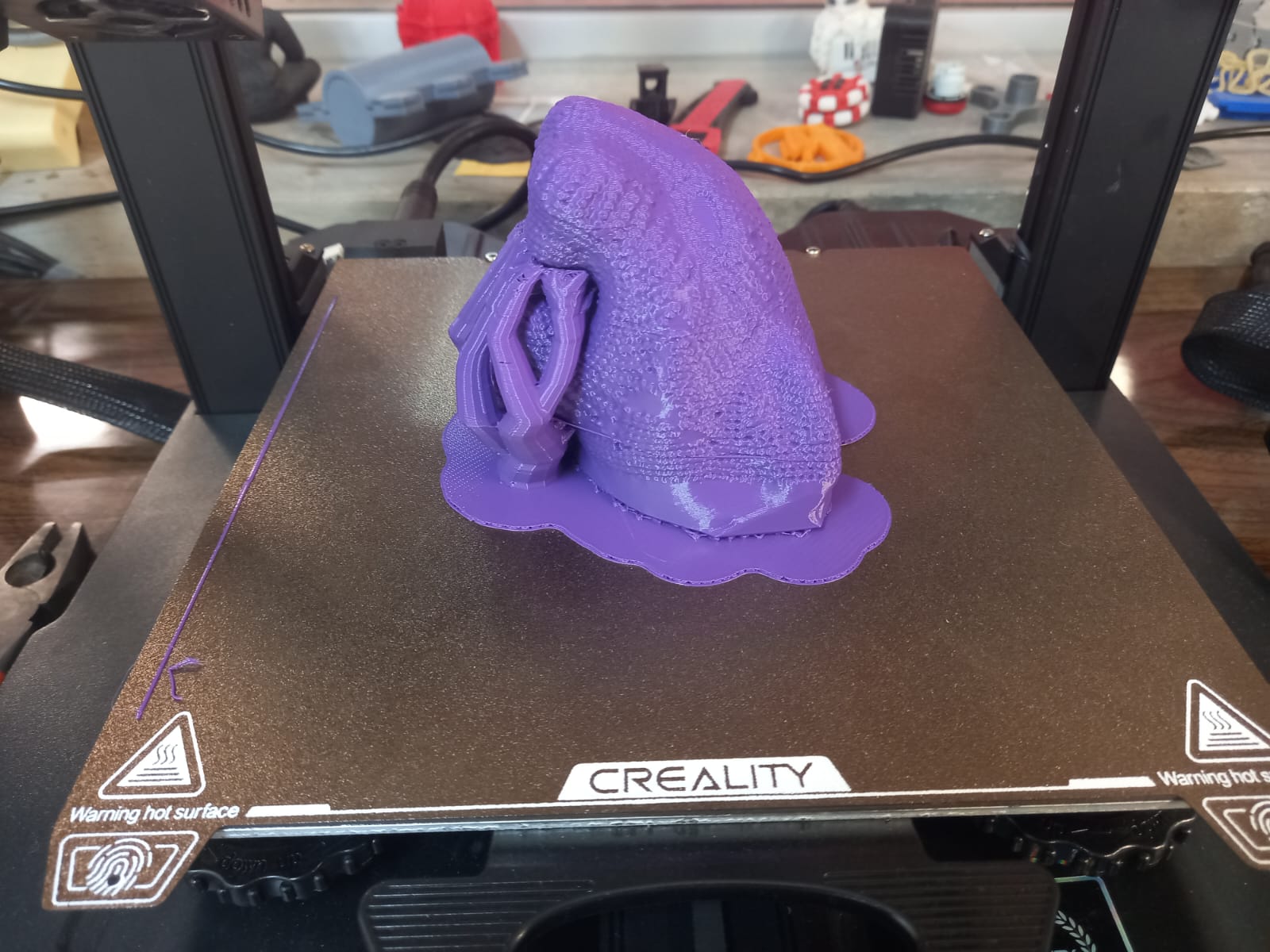
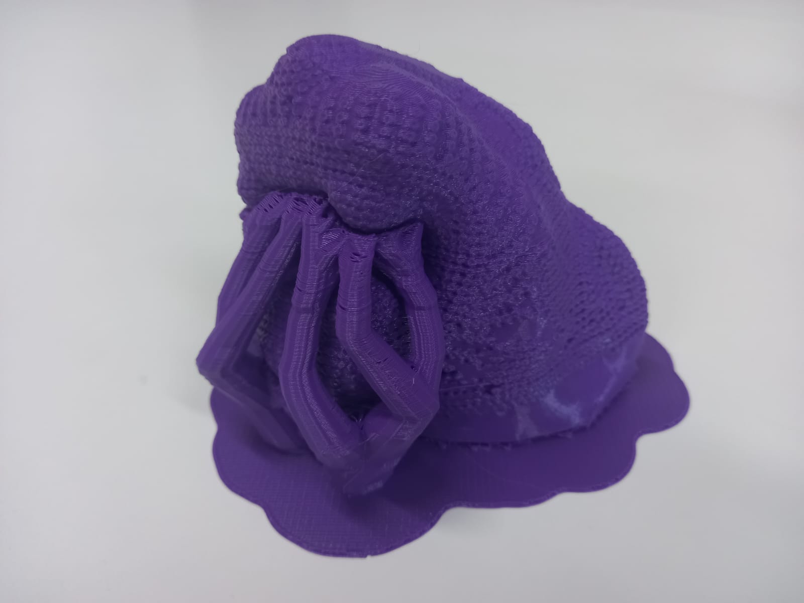
We will open the 3D printing software Cura-Ultimaker and prepare our print. On this occasion, to avoid deformation of our figure, the program recommends using supports. My choice was tree support because it uses less material.
Slice and this is the final preview.
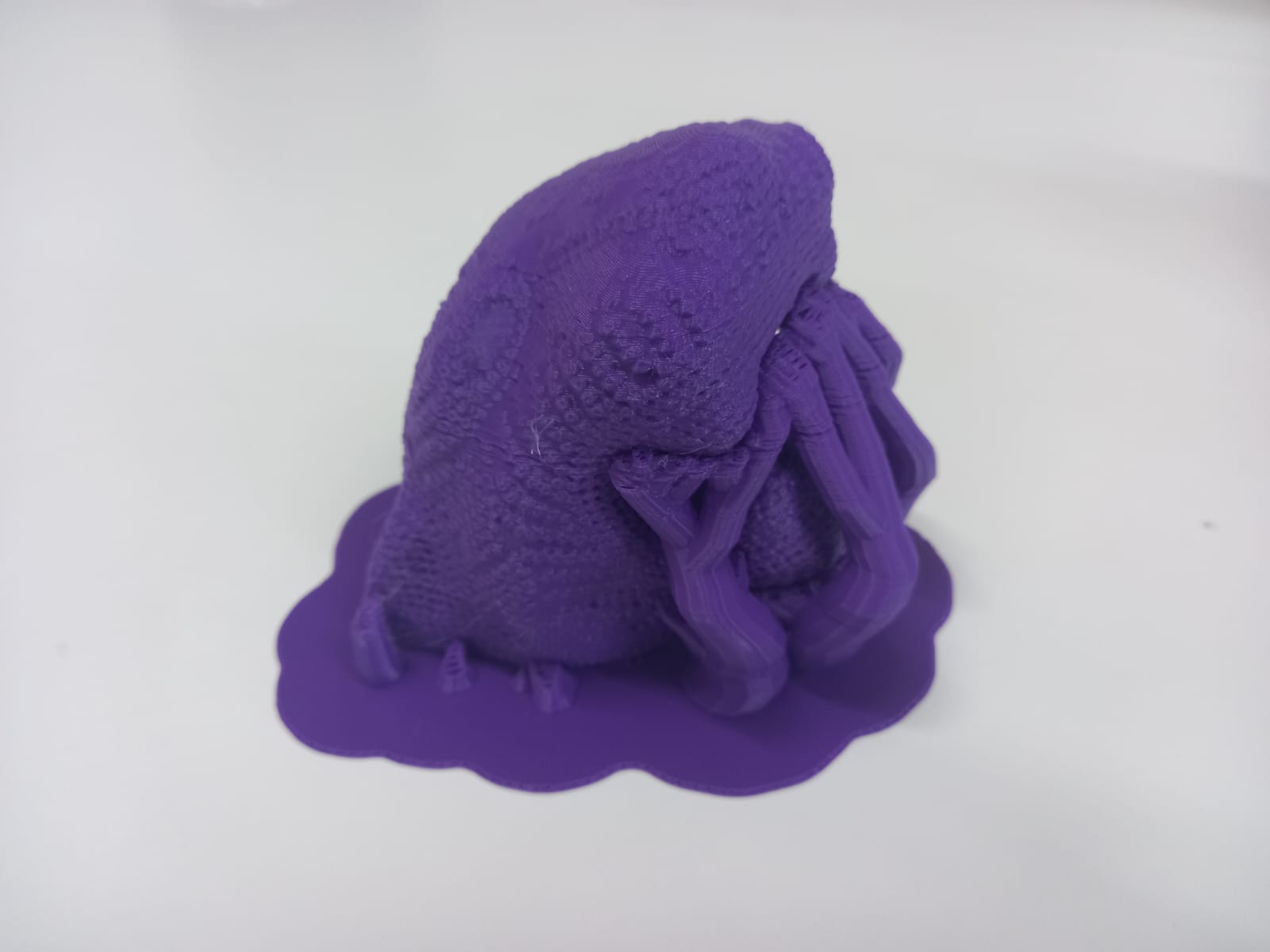
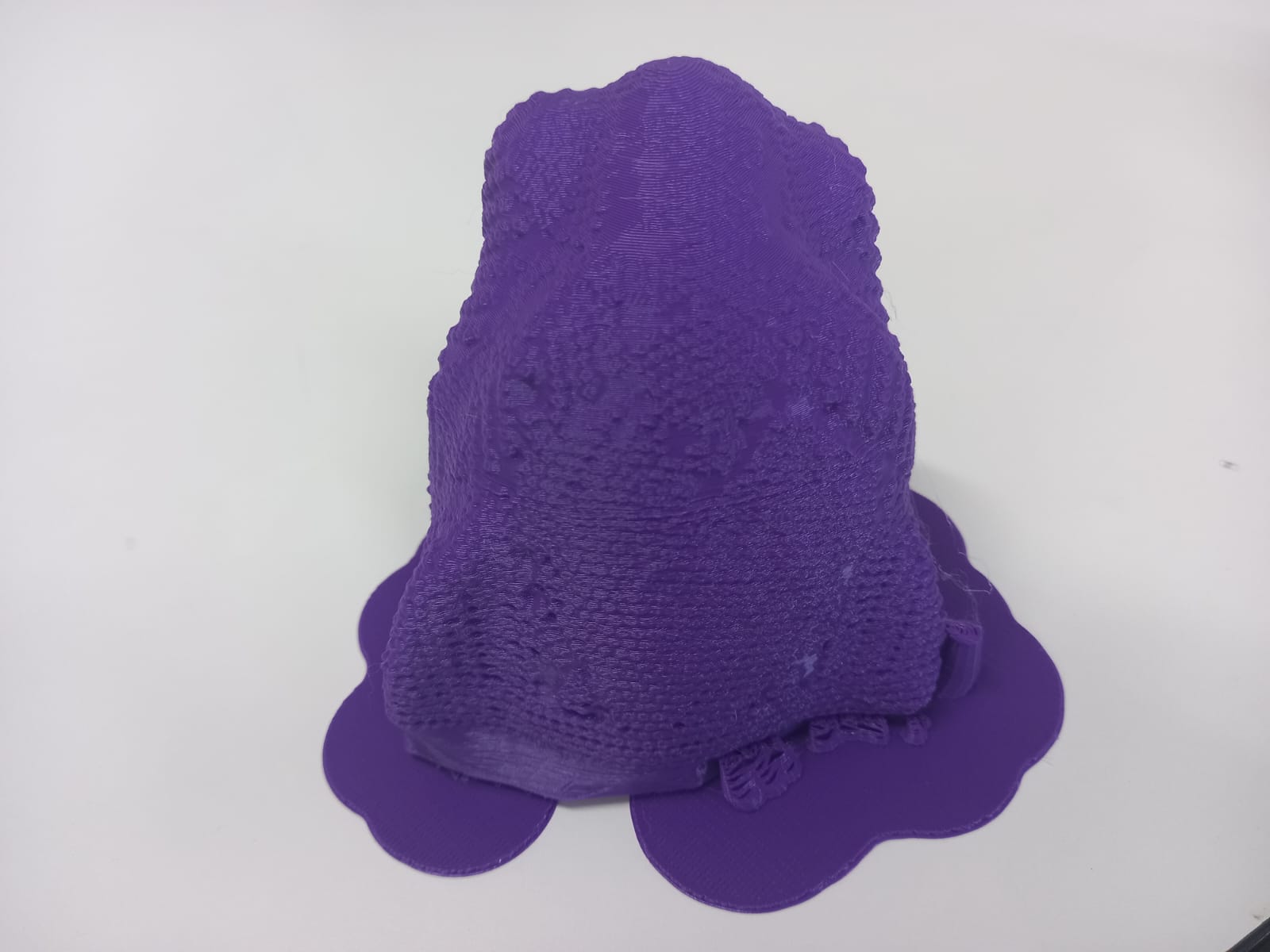
The 3D print process gallery
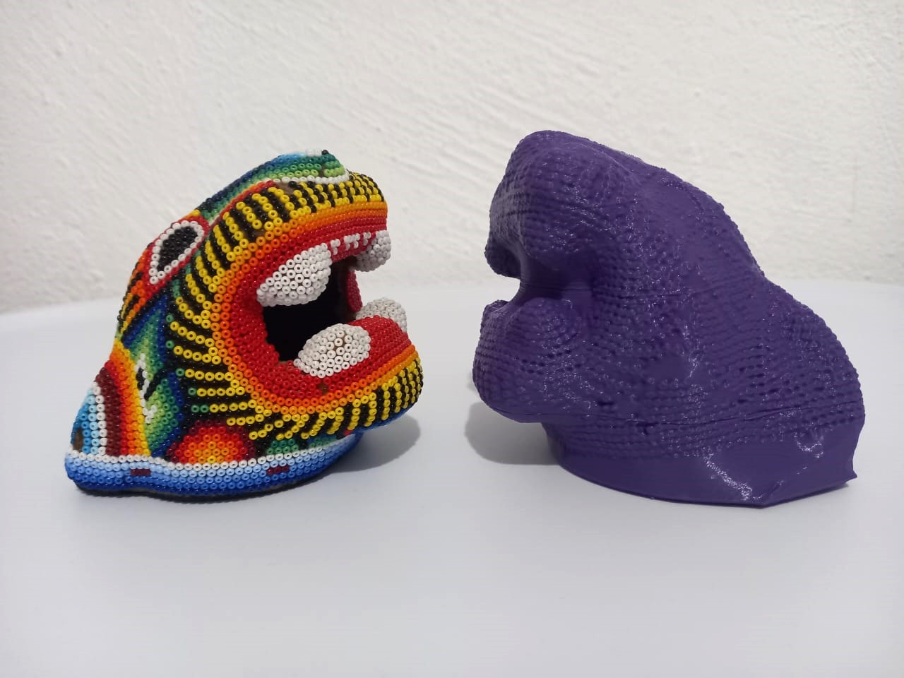
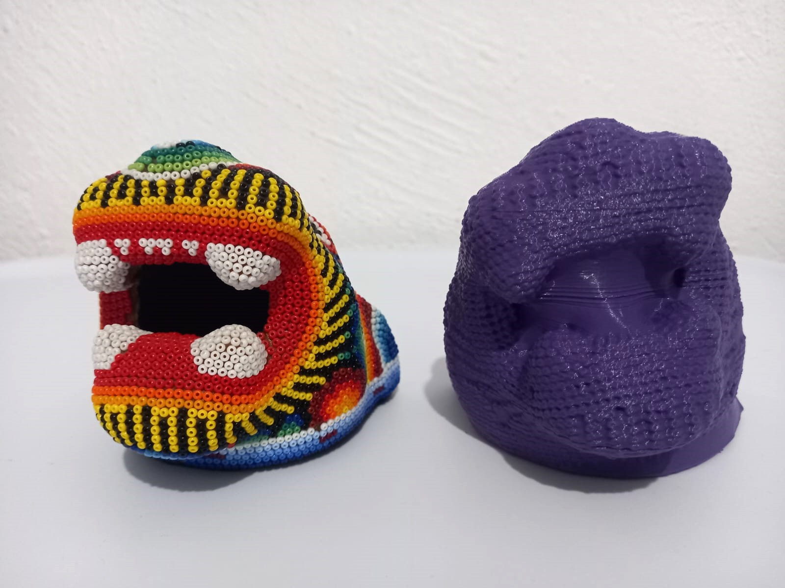
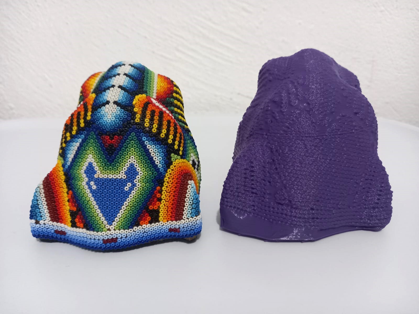
Comparison
It's great that the texture of the original object has been preserved in the scanned object.
Files
- Fidget STL
- Fidget Solid Part
- Fidget Gcode