3. Computer Controlled Cutting
First of all, in our group webpage, we explain about power and speed, kerf, joints and more. In fact, there are various steps provided for utilizing the laser cutter. Please ensure to verify your model and its characteristics.
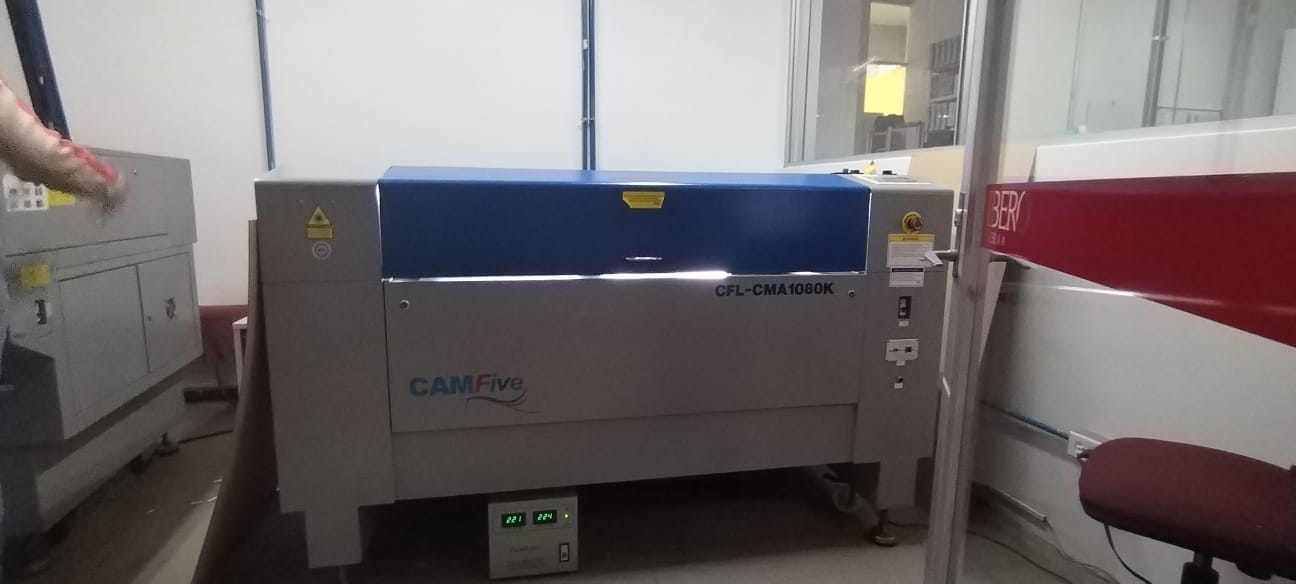
Our fablab uses this machine: CAMFive CFL-CMA1080K
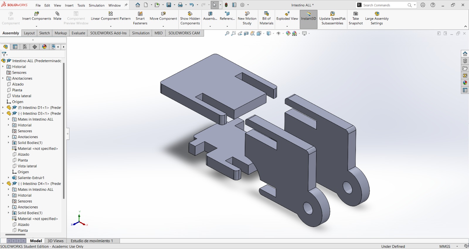
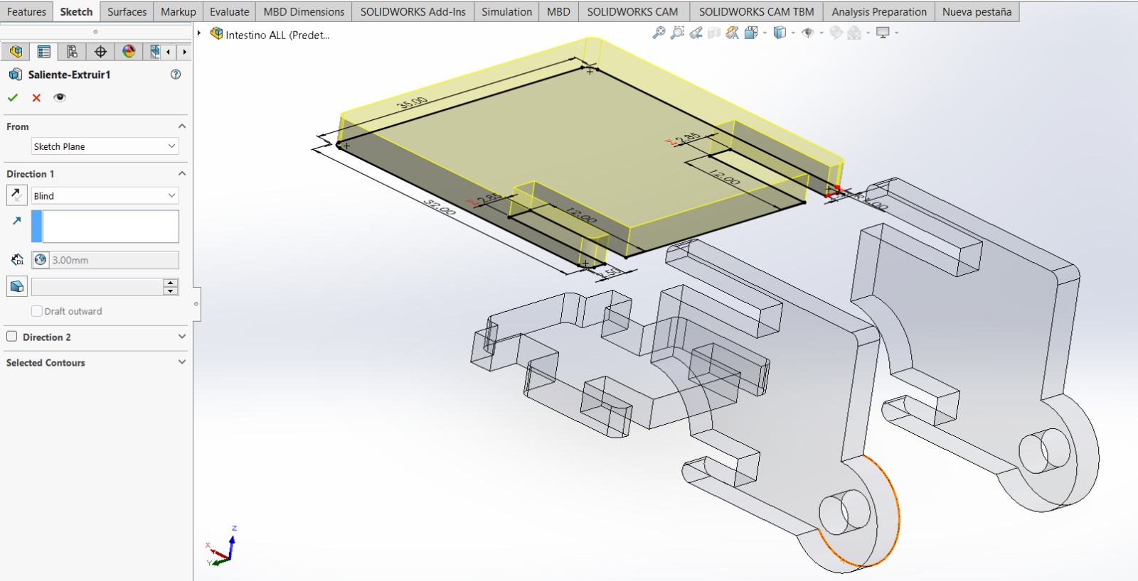
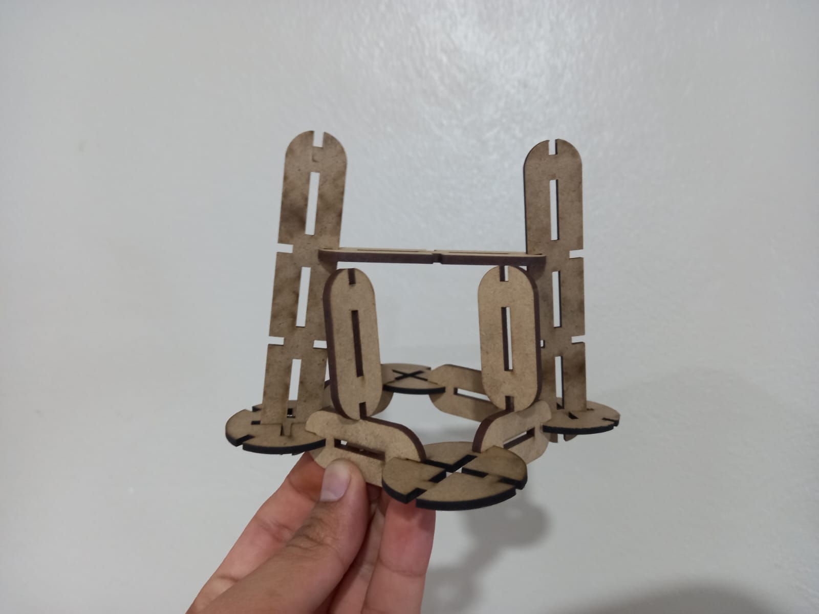
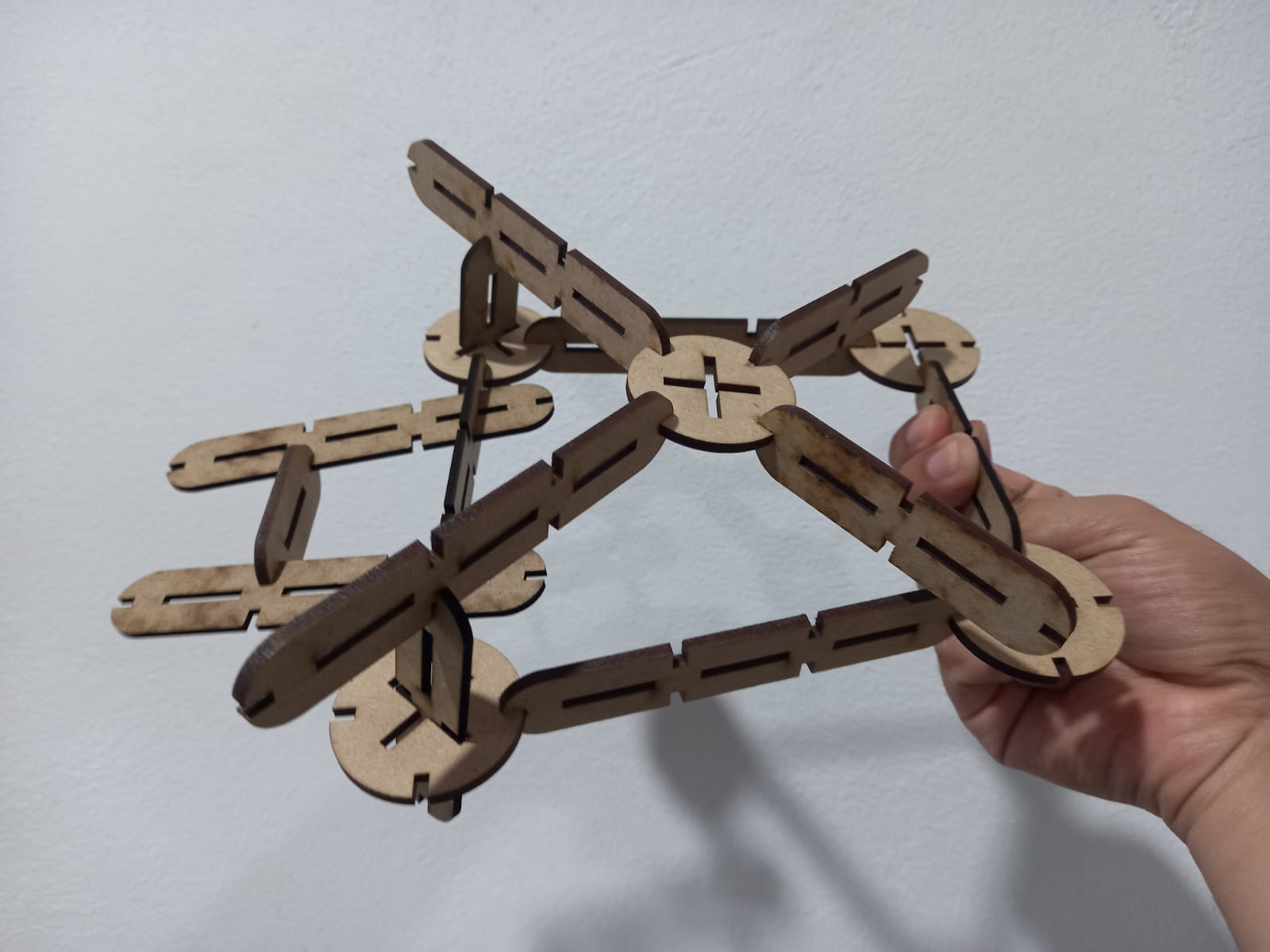
IMPORTANT: I am in the process of building a dragon kit based on my learnong, even though it's not completed. I'll use it to document the steps for this week's activity. (The italic paragraph refer to the components of our construction kit.) First, I sketched some components to assemble them in SolidWorks, allowing the creation of a chain. This will serve as one of the links of our dragon.
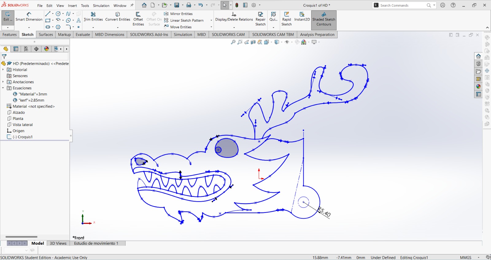
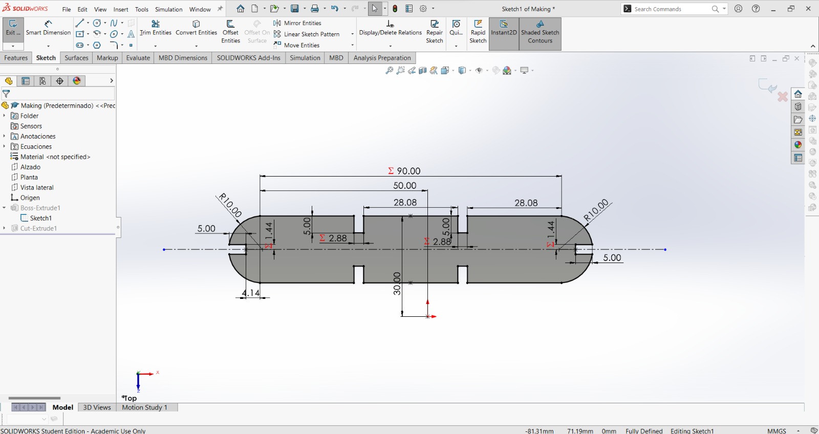
And this one is the sketch of our construction kit.
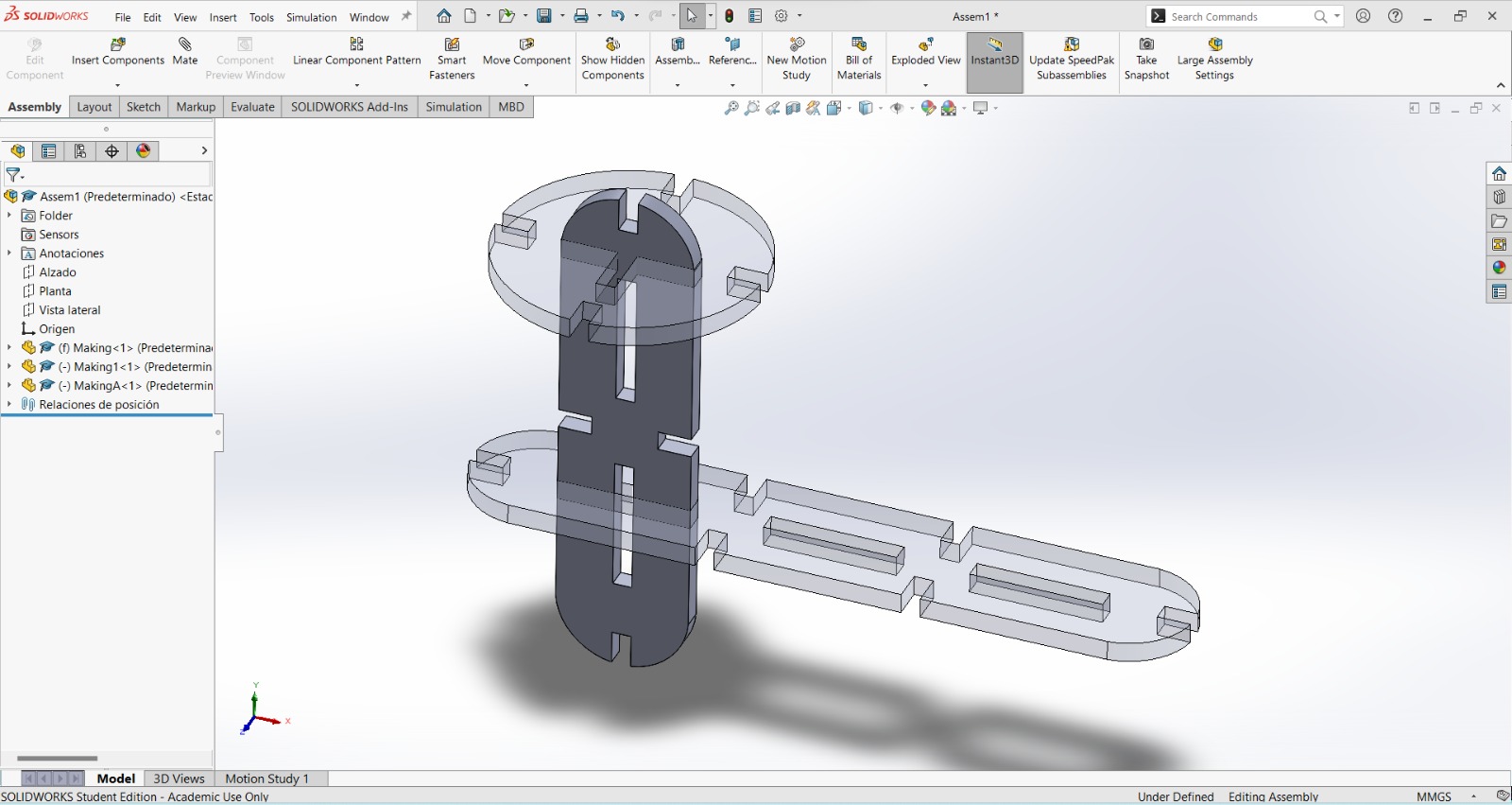
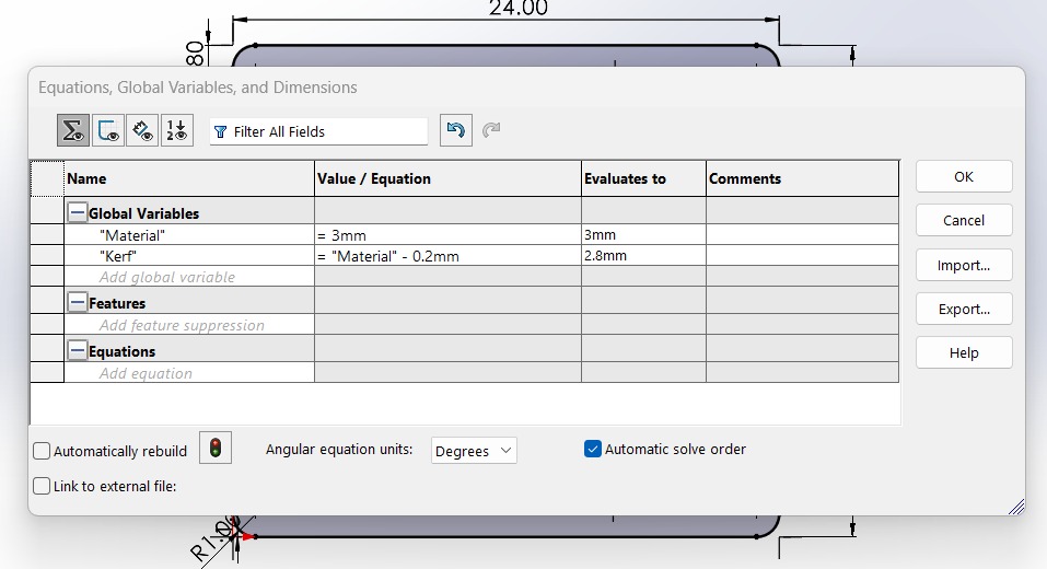
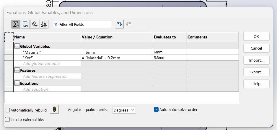
However, it needs to be parametrized; for that, we will use the option: Equations.
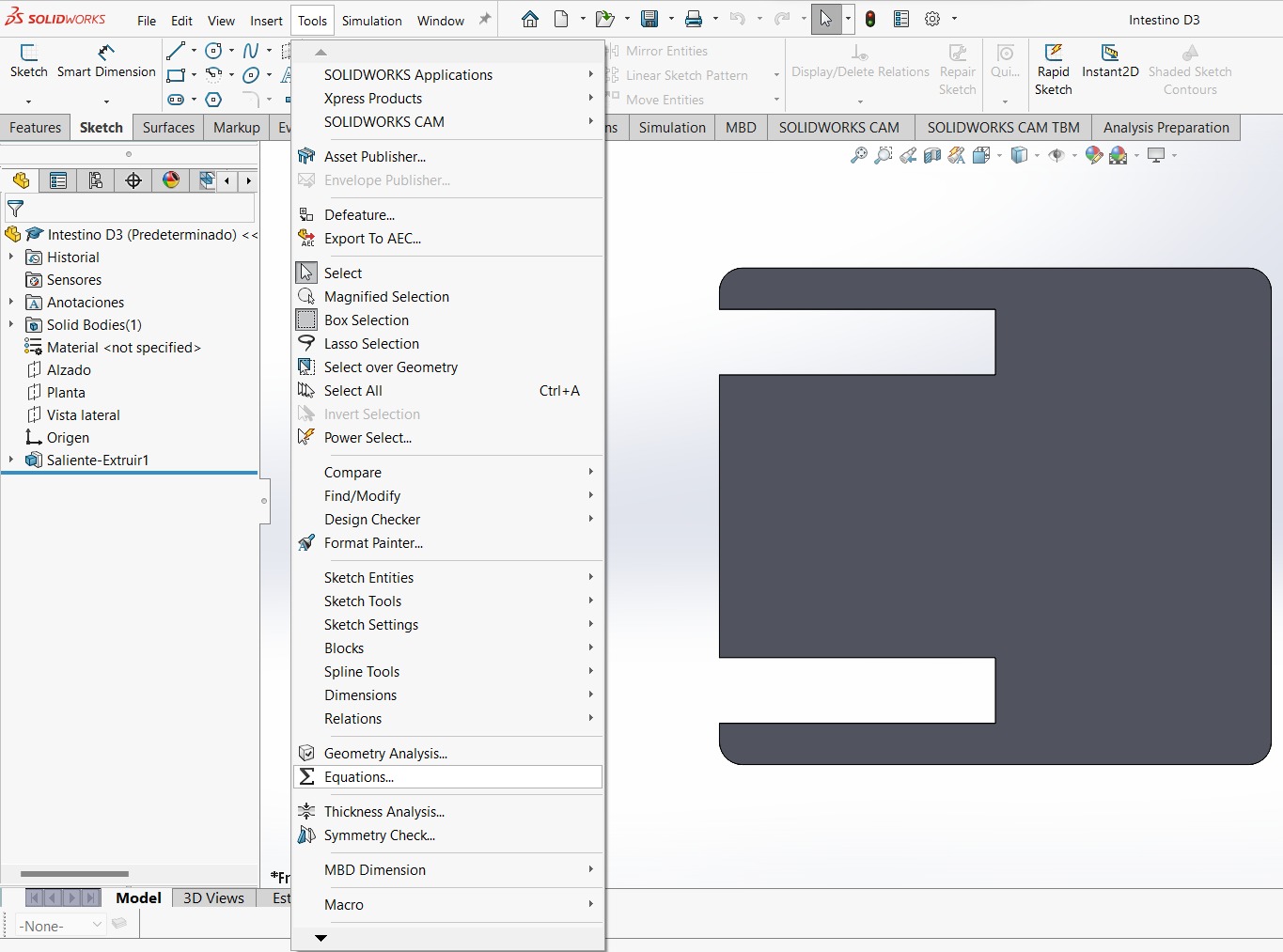
Here, we assign a dimension to facilitate the easy modification of our design, adapting it to our requirements. Note: this is done with each piece of our design.
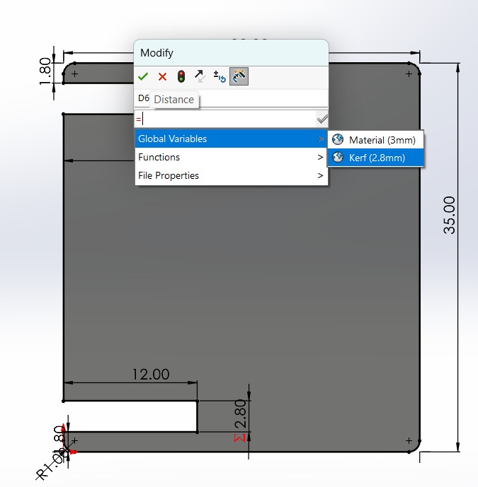
Now, using Smart Dimension, instead of giving it a numerical value, we write the "=" sign and select our global variable. This step is IMPORTANT, as it won't function otherwise.
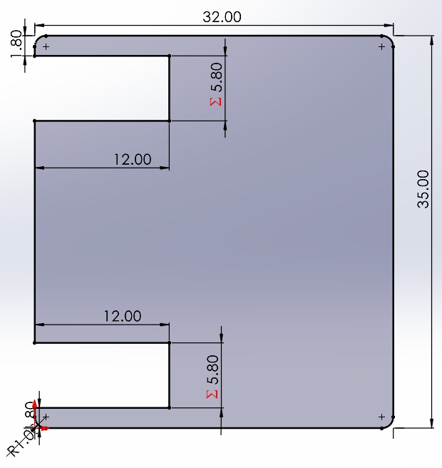
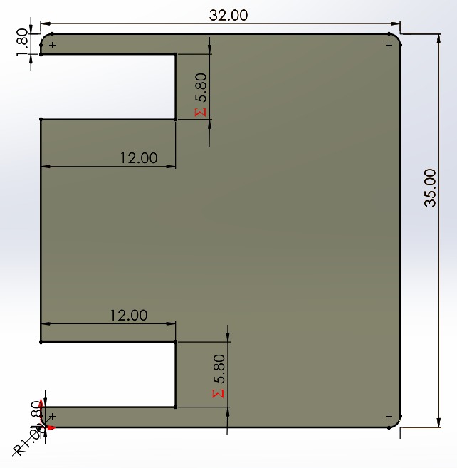
We will notice that we have done it correctly when the red summation symbol appears in our measure:
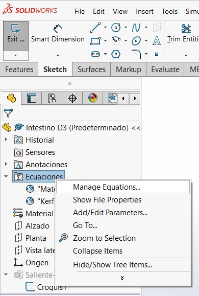
If we want to access our equations again, we just need to right-click on "Equations" and then select "Manage equations".
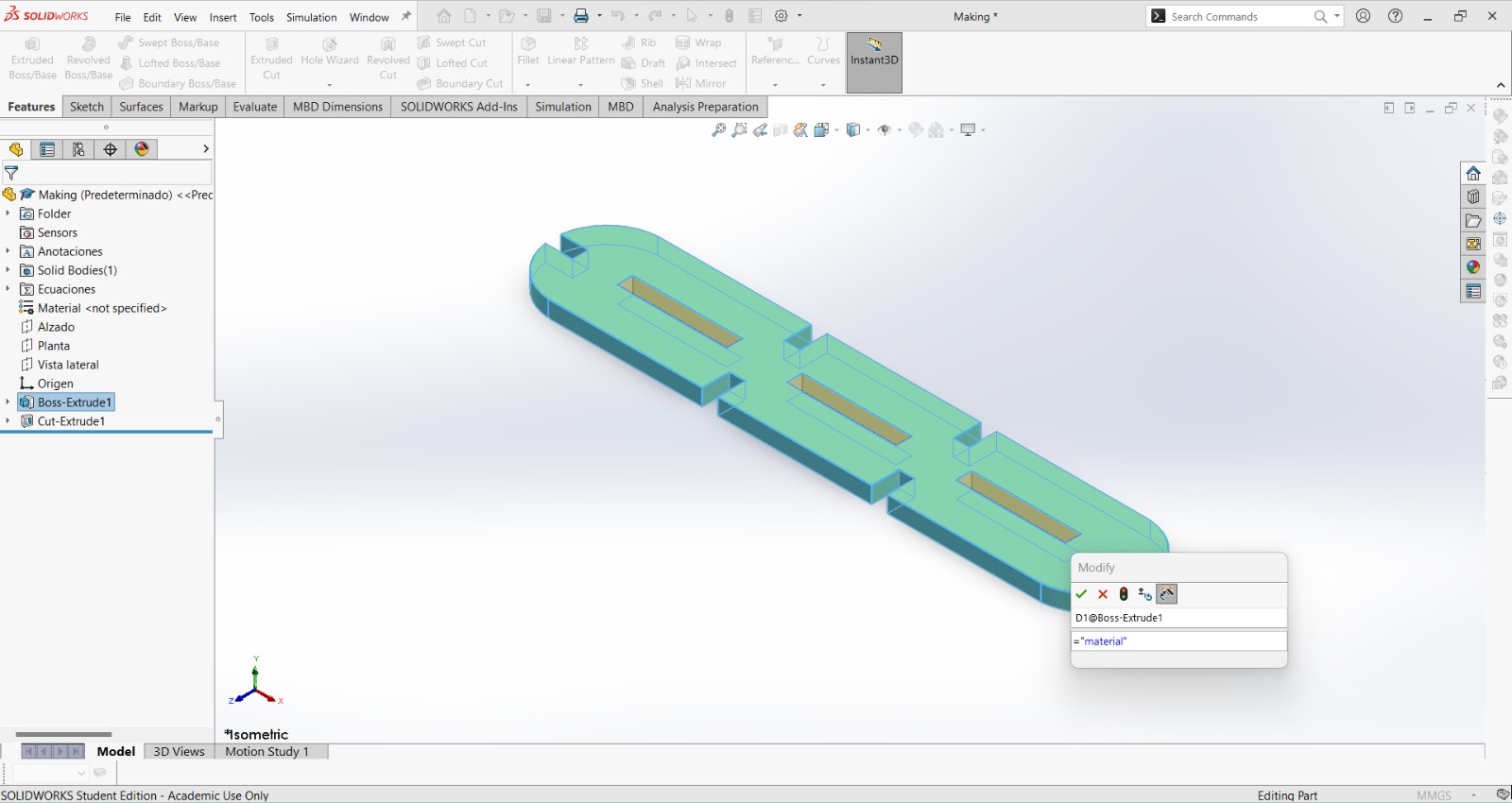
Now, if we change the thickness value of our material, everything will automatically adjust. Remember to select Automatically rebuild option.
WOW! Magical. We will do it like this for all our dragon pieces.
Don't forget to parameterize the material thickness as well.
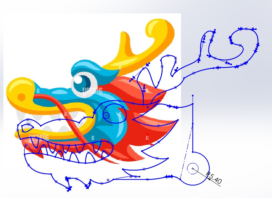
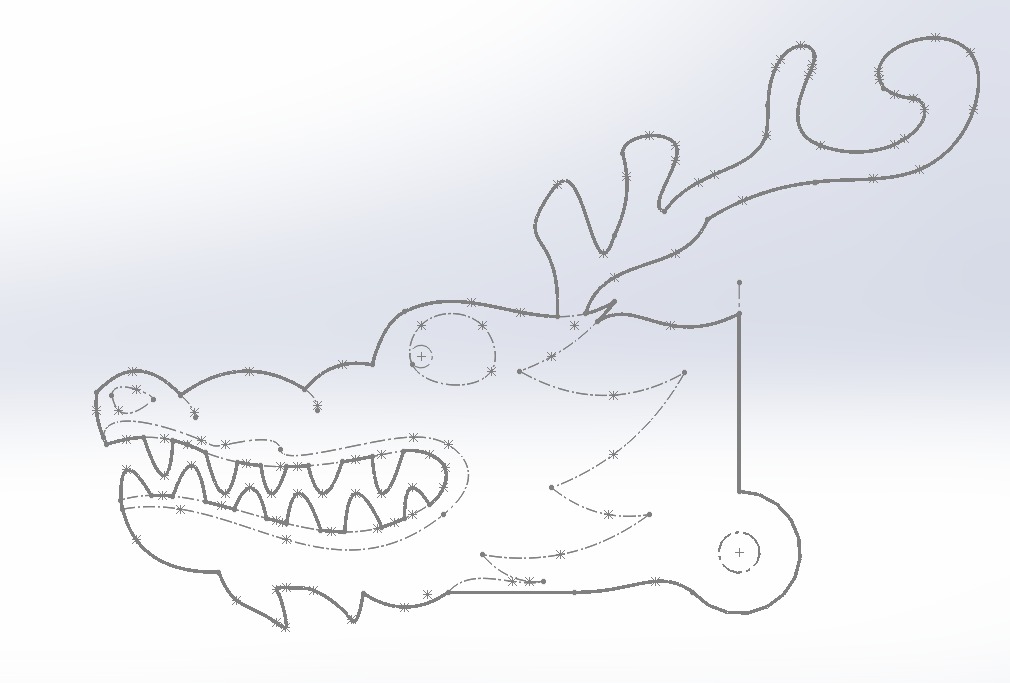
Sketch the dragon head.
Draw its tail and legs too.
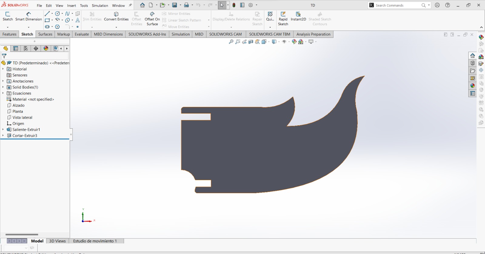
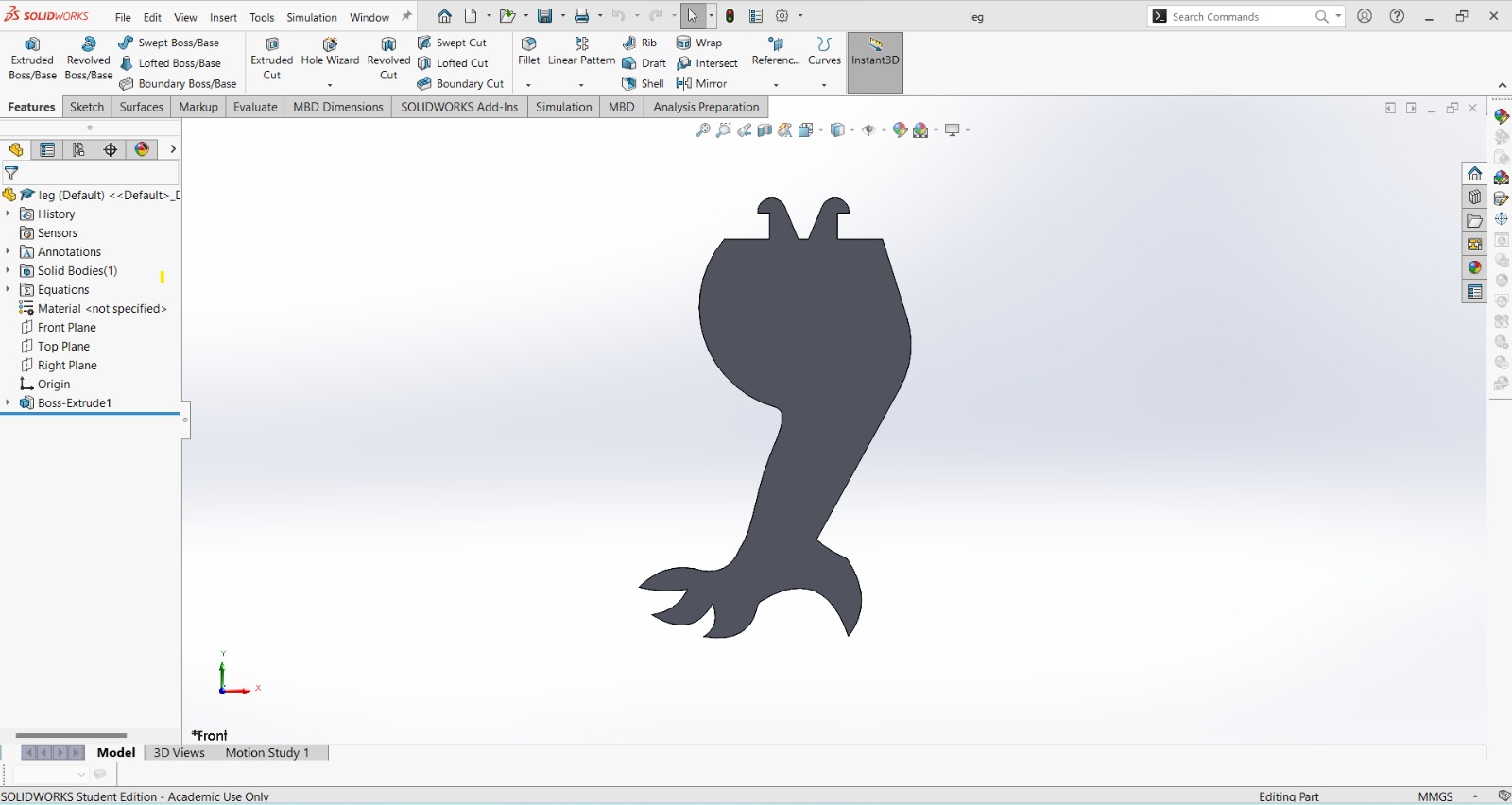
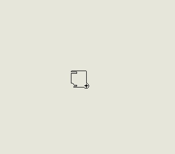
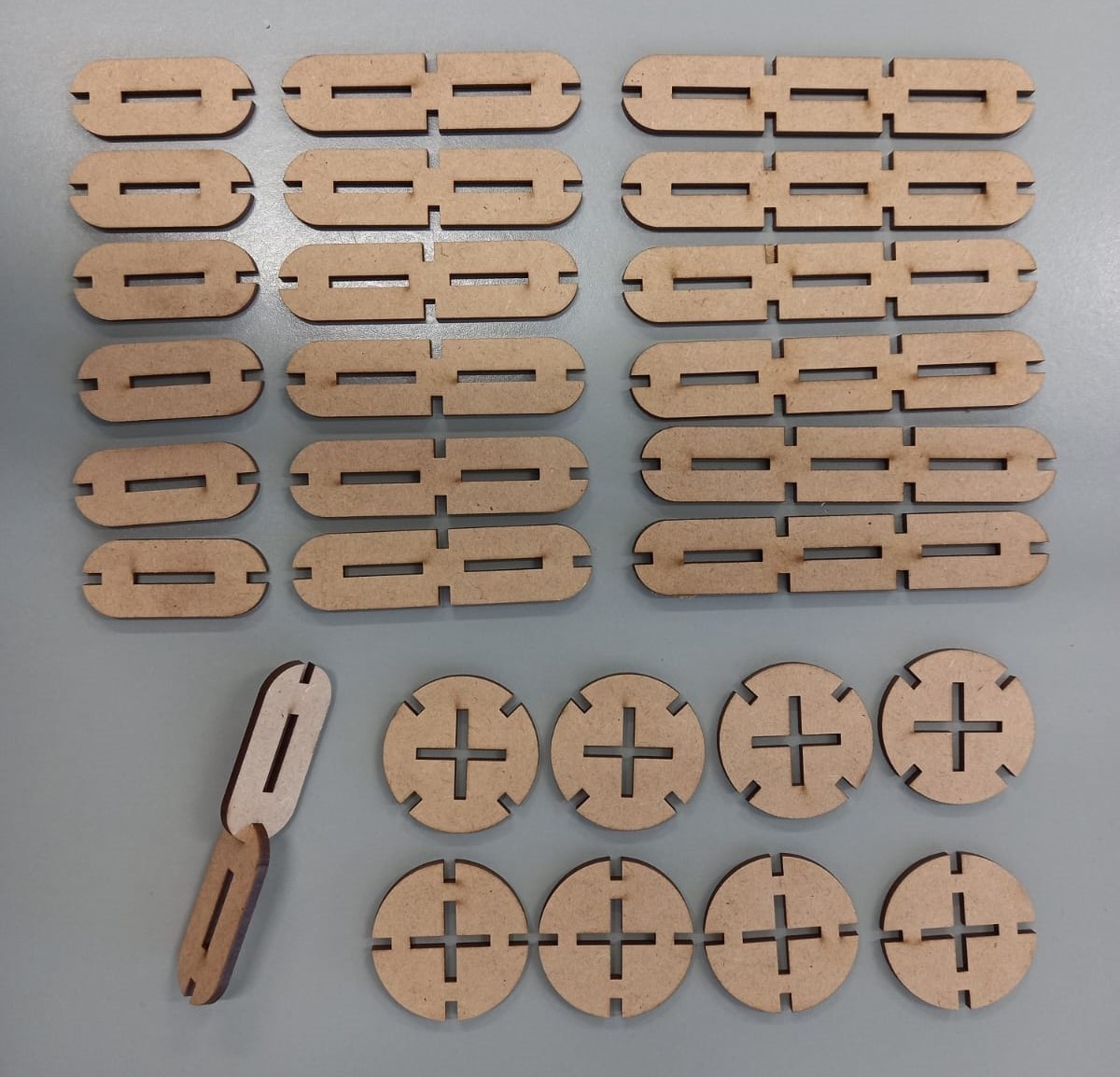
With our construction kit piece, it would look as follow:
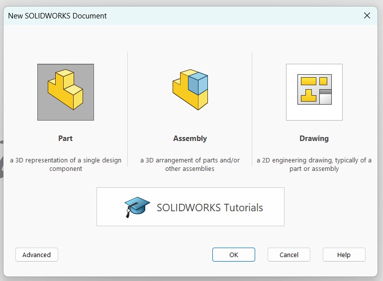
Then, make a new file and select drawing.
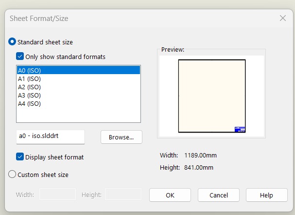
Select the sheet size, mine will be A0
In theBrowse option, we will select our files, one by one.
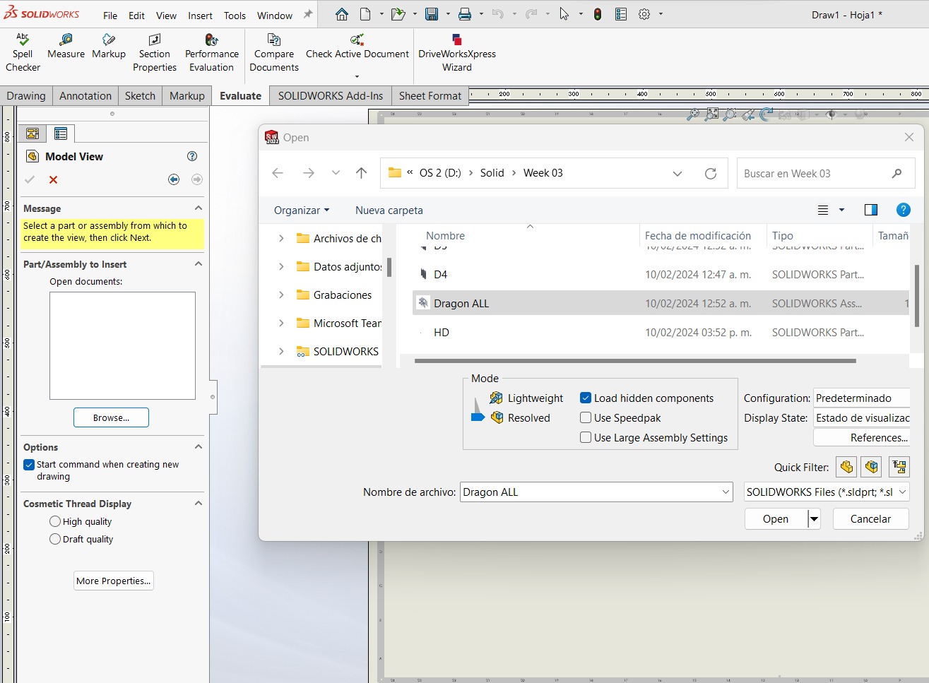
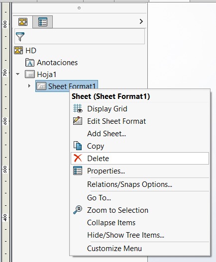
Next, right-click on sheet format and delete it.
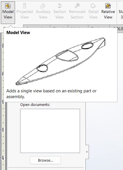
In model view you can continue adding more components.
Oops it's too big. In custom scale option, you choose 1:1 (original size)
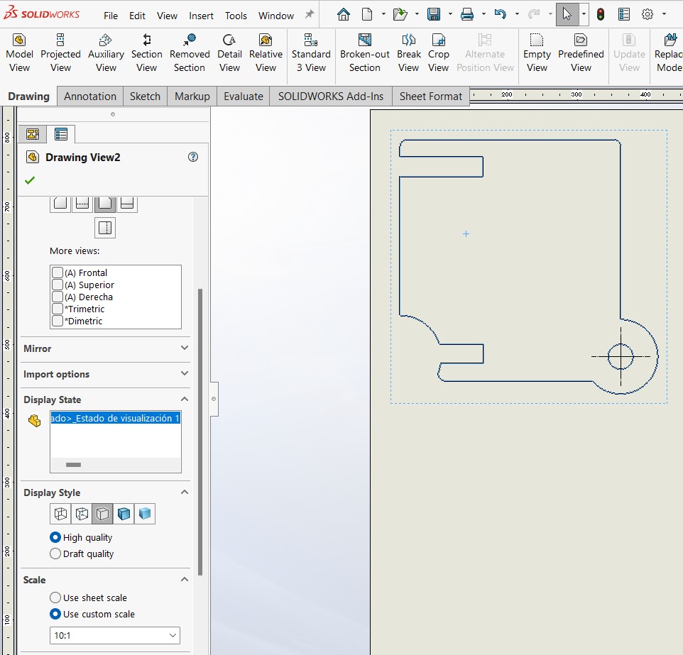
Perfect and tiny.
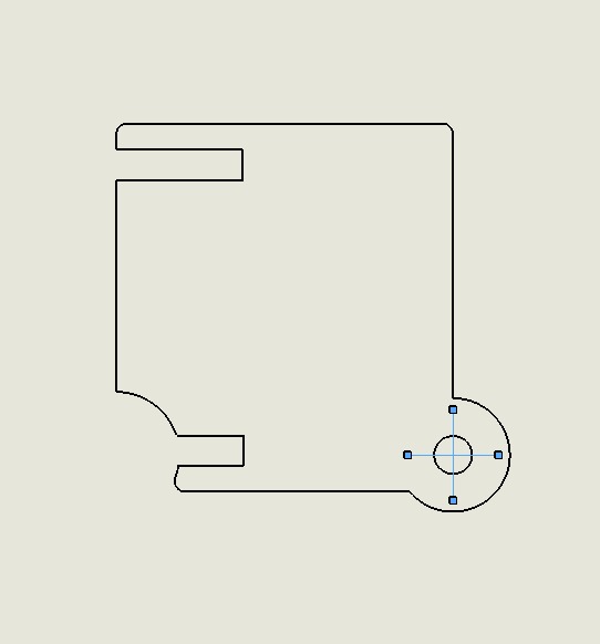
Delete reference lines while sketching.
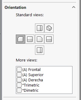
To mirror your piece, select Back in Orientation.
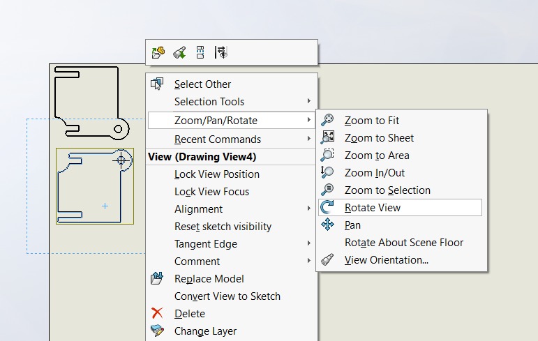
Here, you can rotate your piece. I'm doing this to avoid the pieces from looking burnt just on one side.
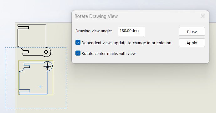
Photos to explain better the previous idea.
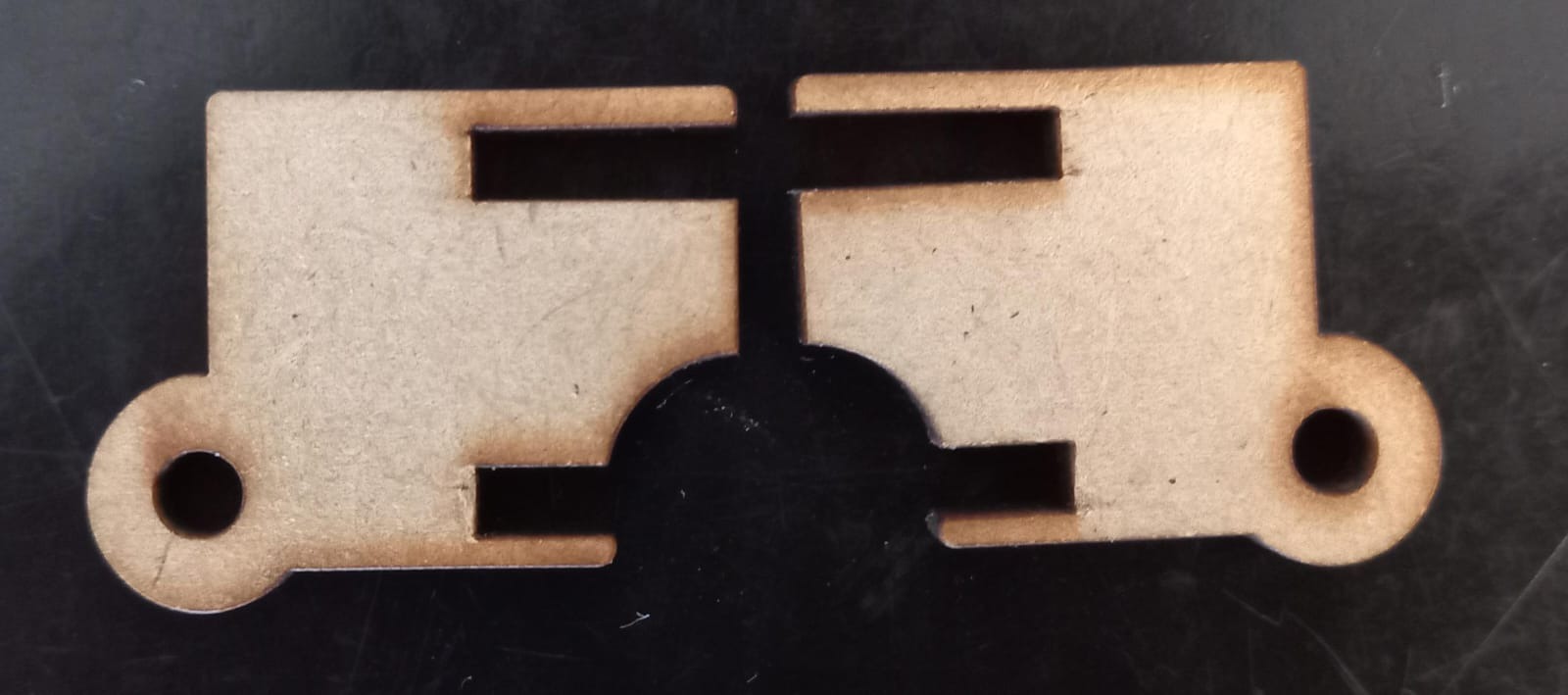
With mirroring and rotation.
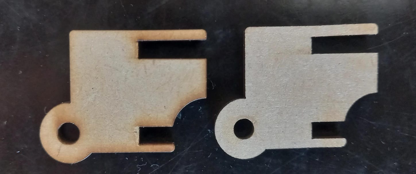
Without mirroring and rotation.
I prefer the burnt side because our dragon is not chilly: it's on fireee! Here is our drawing, and we save it in DXF format for laser cutting.
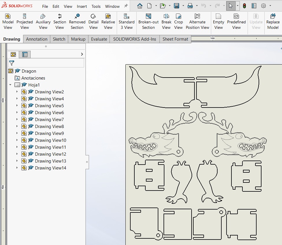
The following is the kit construction drawing
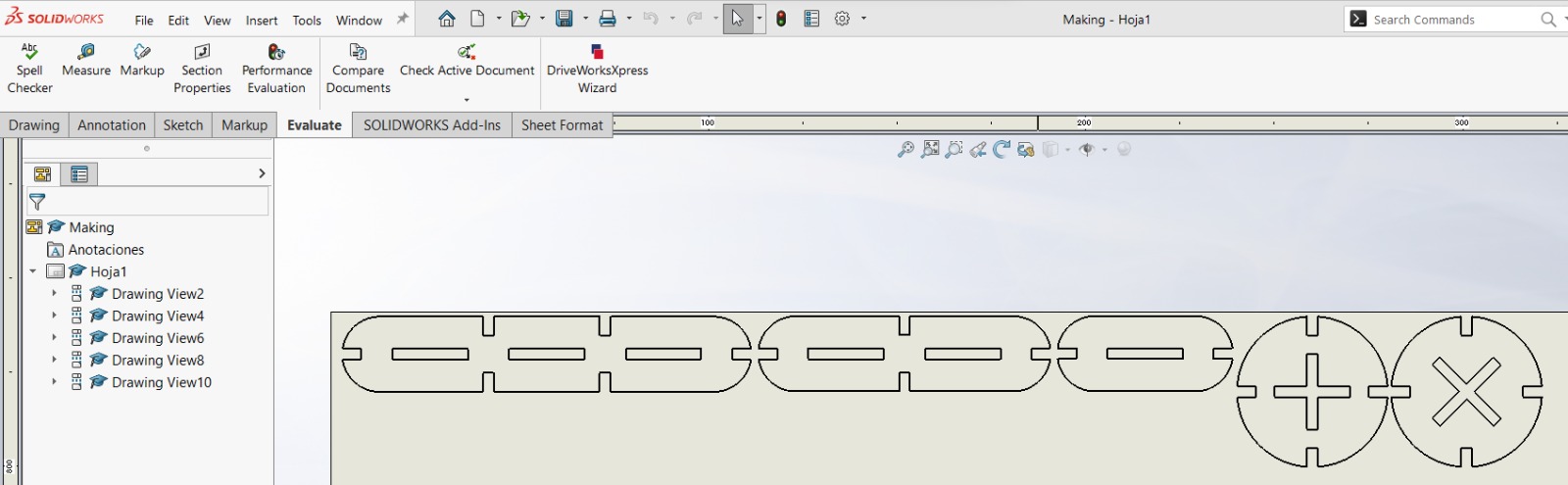
Here we go!
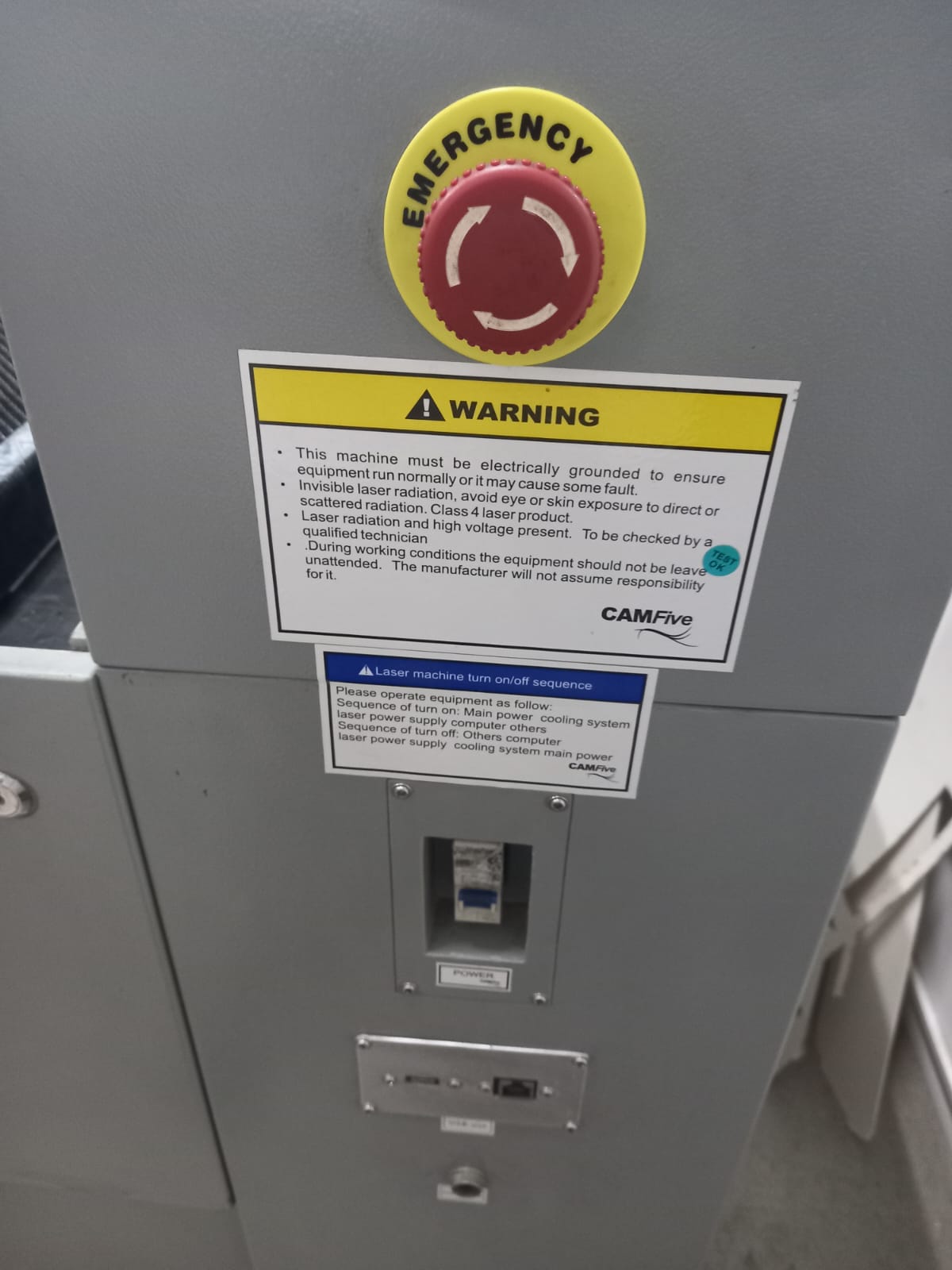
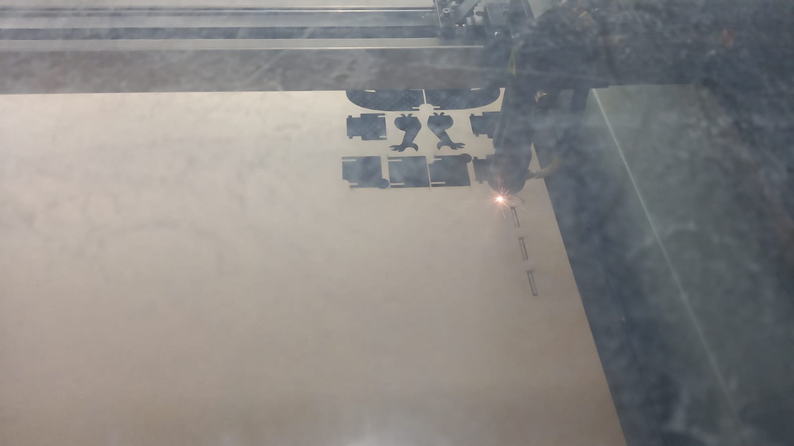
Laser Cutting Machine
First, we power up the energy station, initiating the cooling process. Then, below the emergency red button, we turn on the switch. We pull the red button towards us, allowing us to press it in case of any potential risk, thereby ensuring user safety.
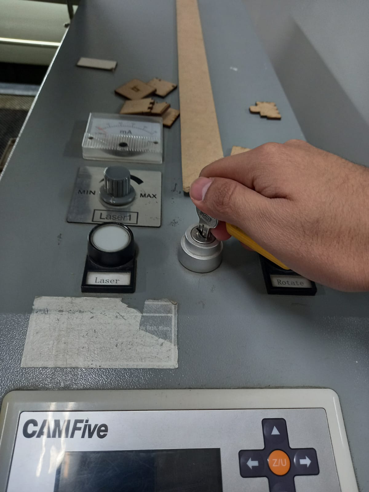
Likewise, the laser cutter's safety system involves turning a key and activating the laser using a button (positioned beside it) alongside a knob for adjusting the laser power. It's all done to avoid accidents.
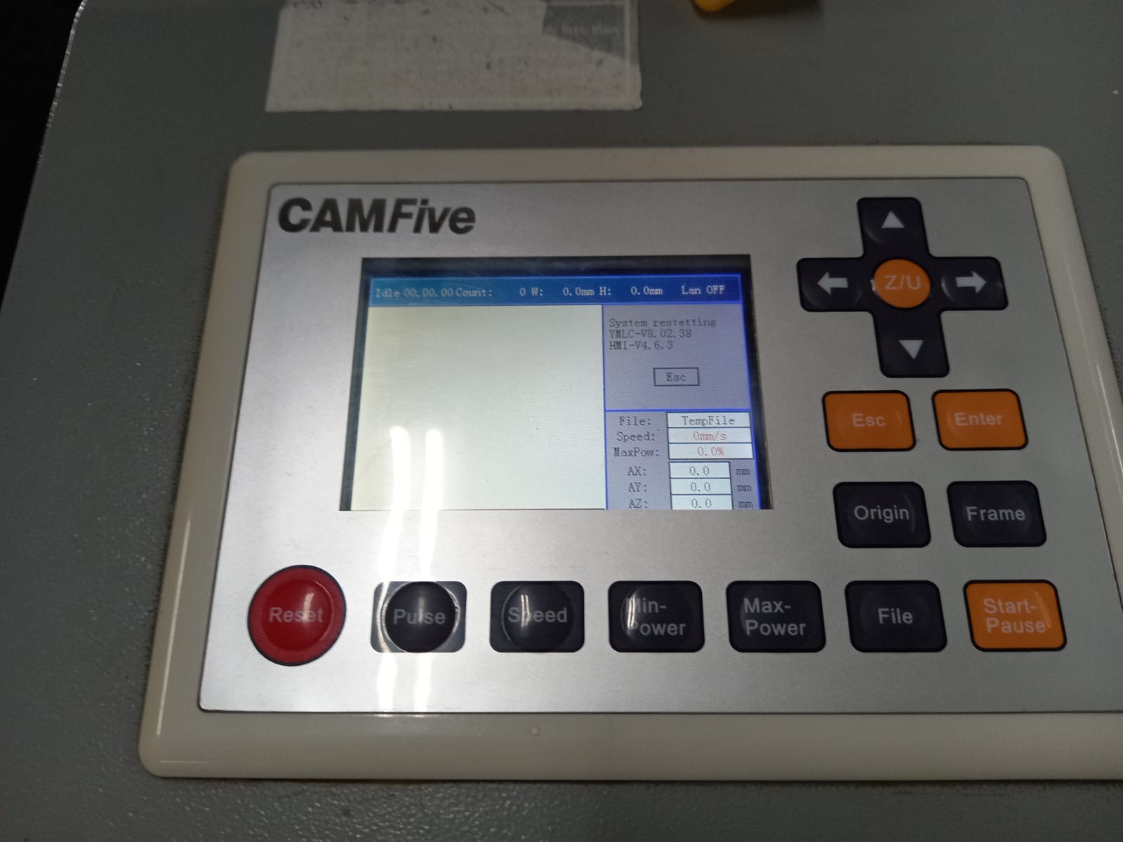
Here is the pad; using it, we can set the laser to the required coordinates.
In the laser cutter software, we place the pieces to be used and adjust the parameters. Thanks to our collaborative task, I used: 60-70 laser power with a speed of 25 mm/s. However, I failed a bit in the kerf because, even though I had done laser cutting before, I didn't know that it can vary a bit even among MDF materials.
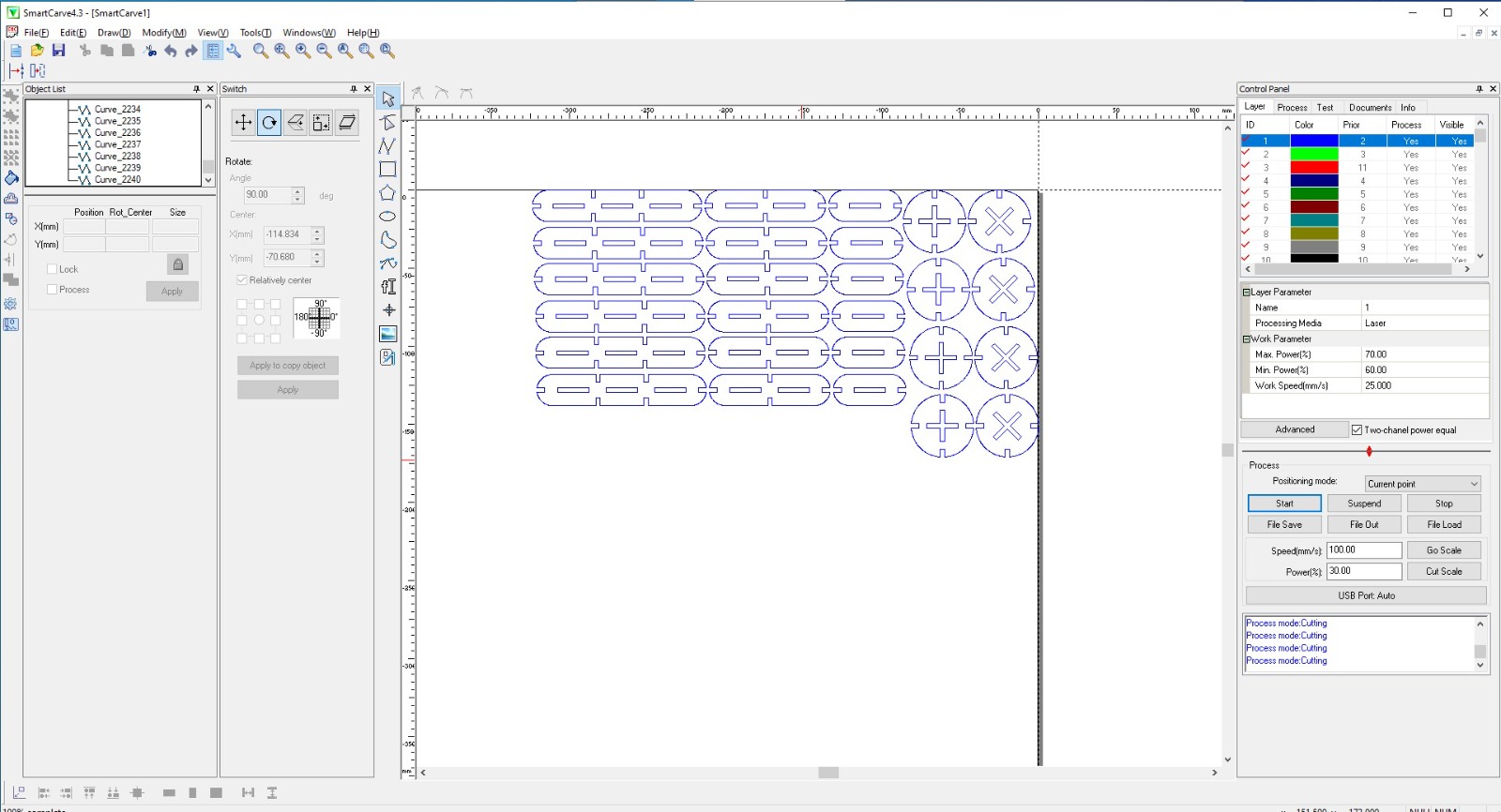
But all went nice.
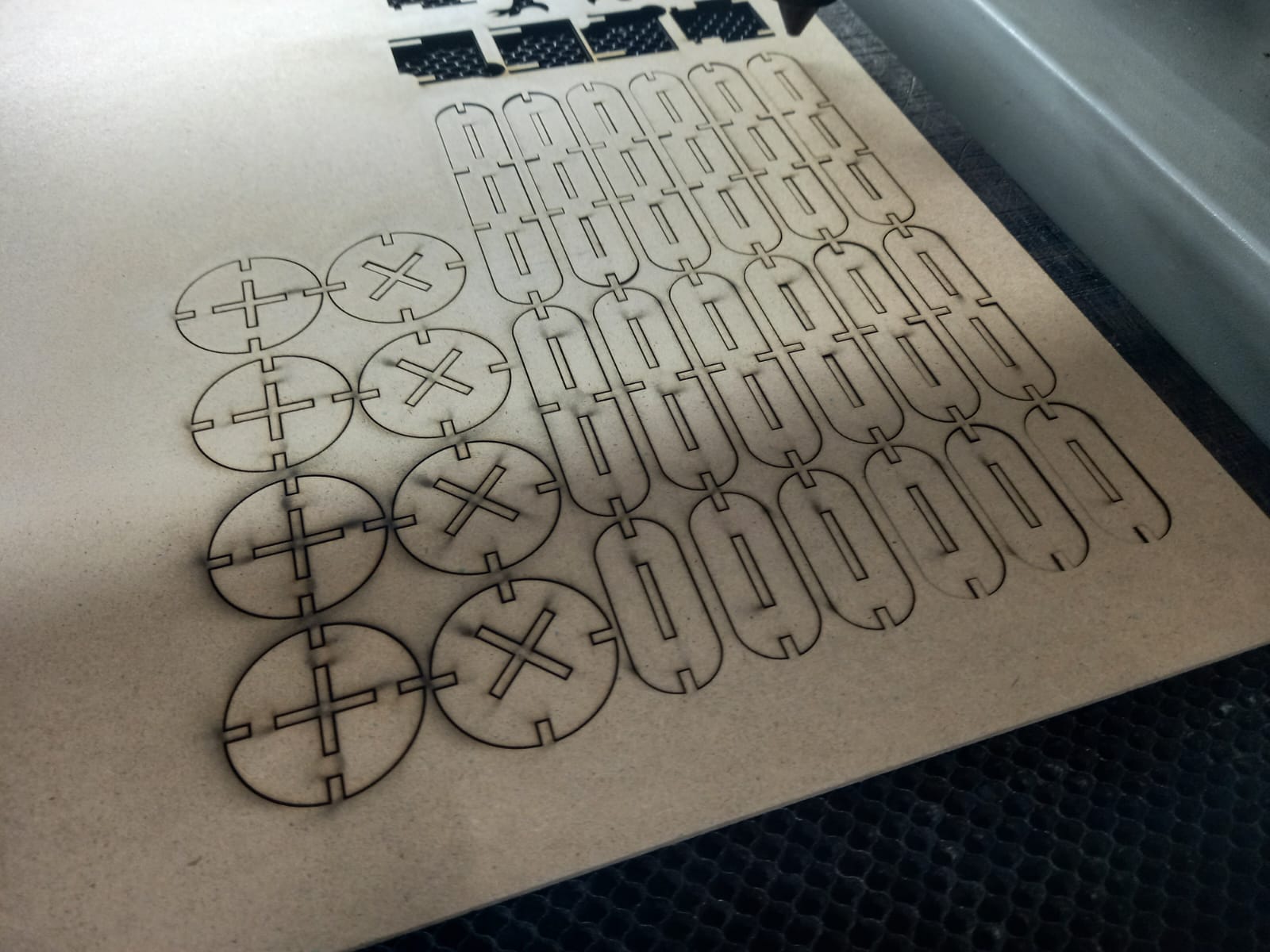
Time to play!
A bunny.
Apache combat helicopter.
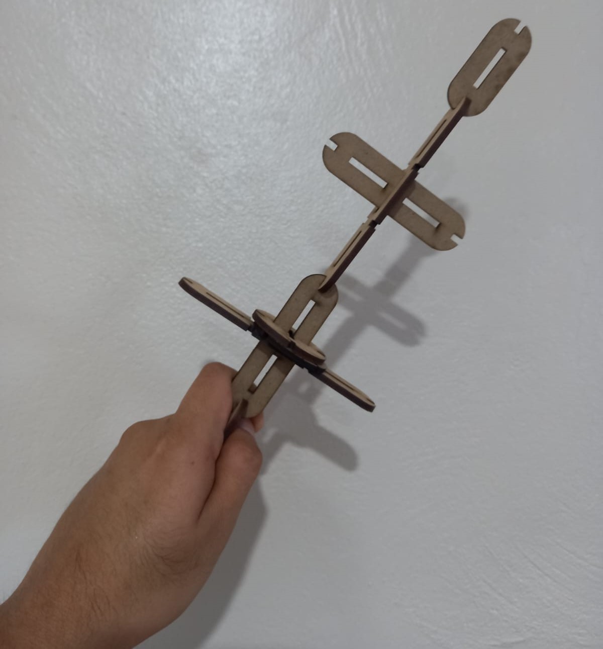
An exoctic sword.
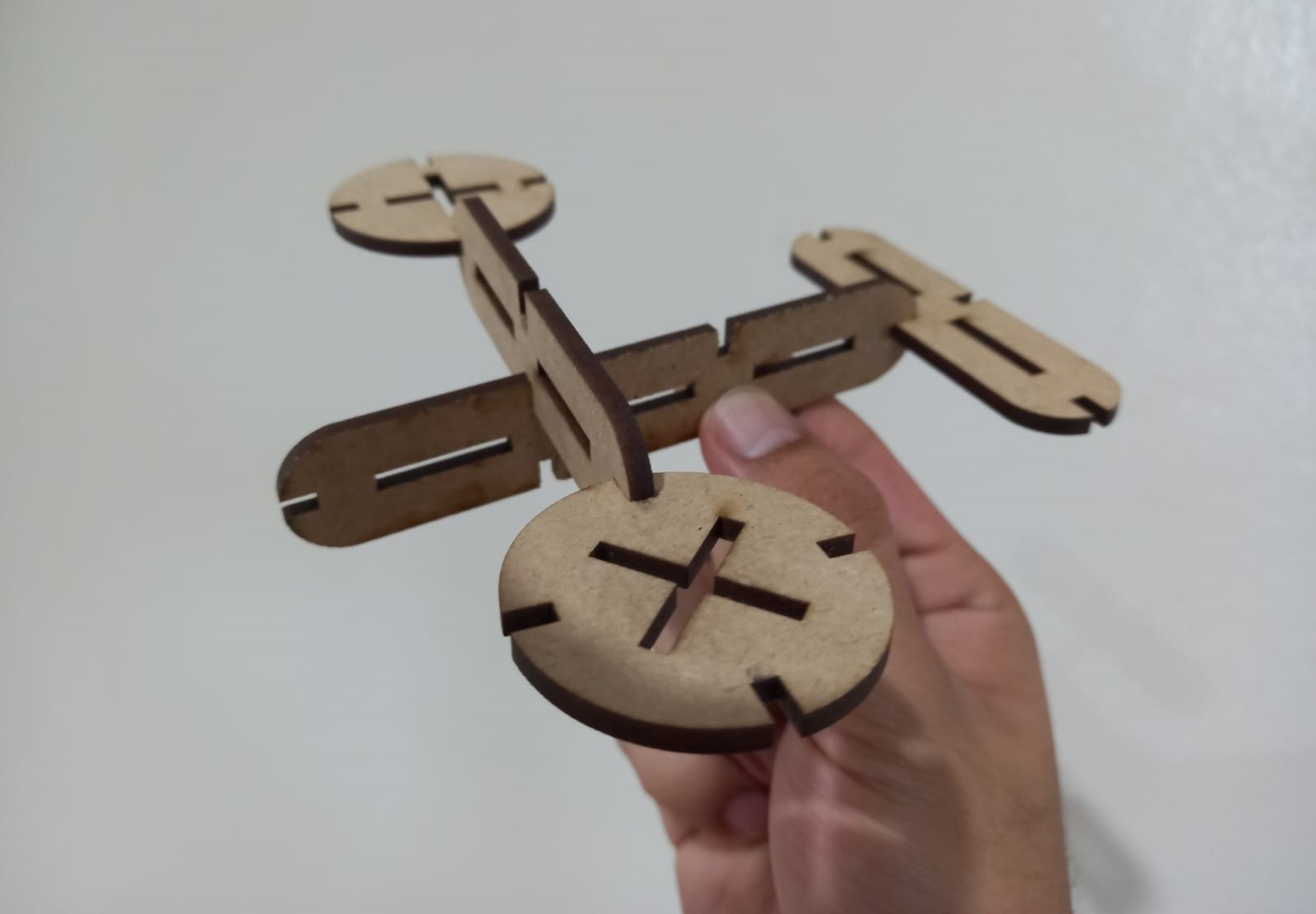
A drone.
Vinyl cutter
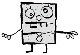
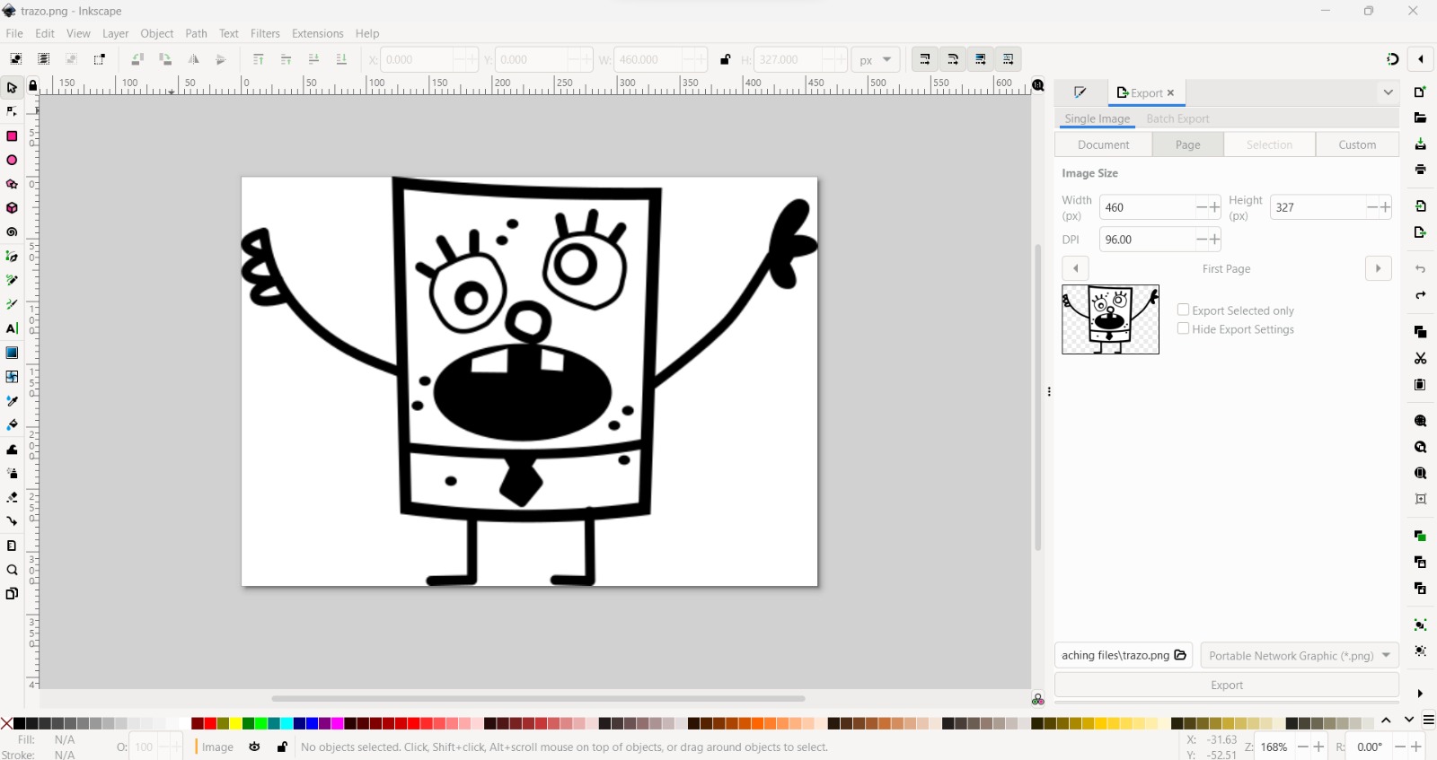
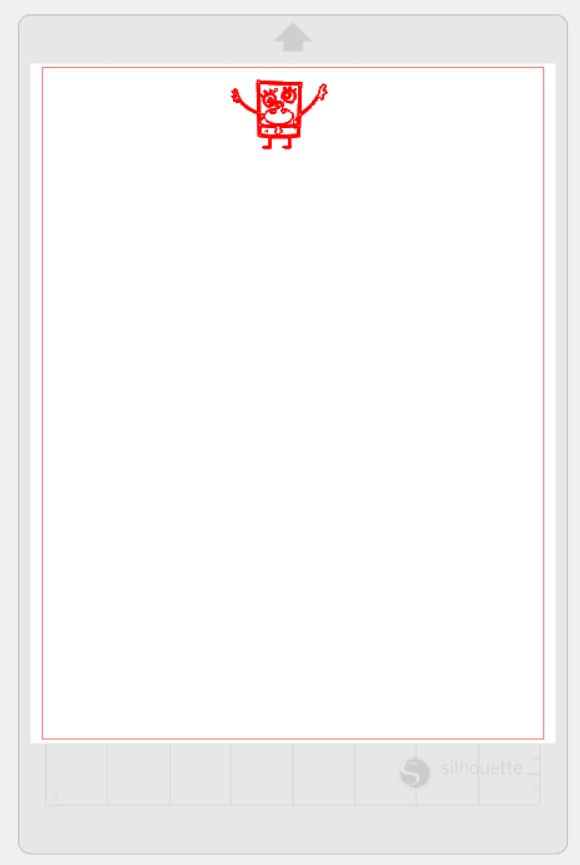
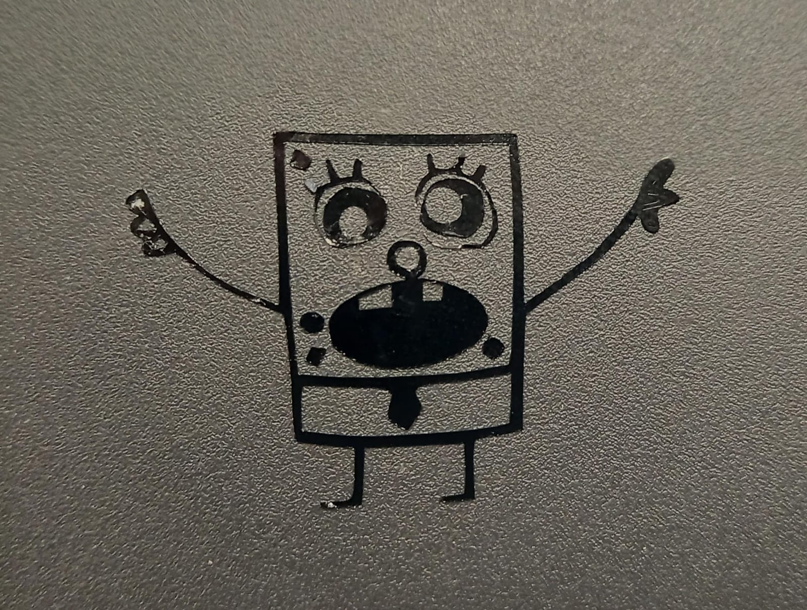
I used inkscape software to design a vector about an iconic cartoon character: "Doodlebob" from SpongeBob Squarepants.
Let's cut using vinyl; for this, download and install the Silhouette Studio program.
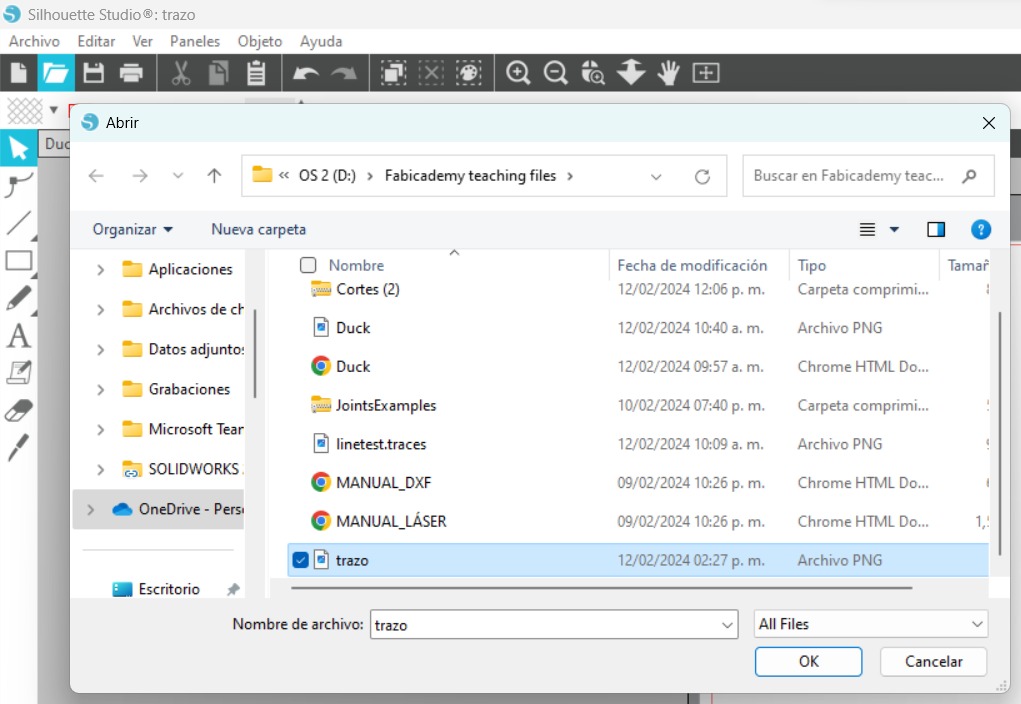
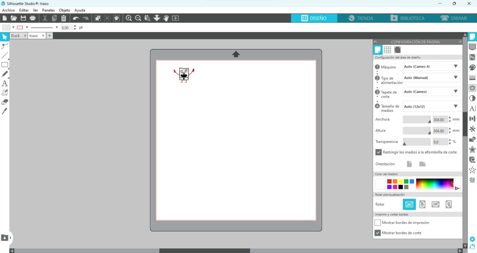
Open Silhouette Studio and png file.
This is the workspace, and we will visualize our image for cutting
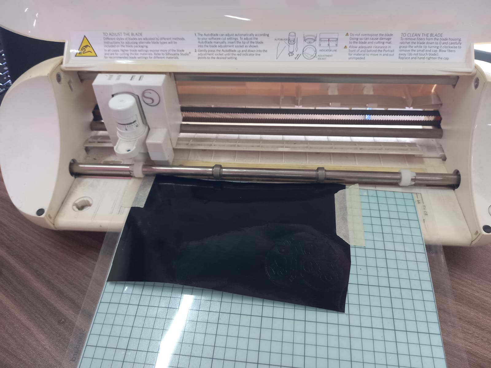
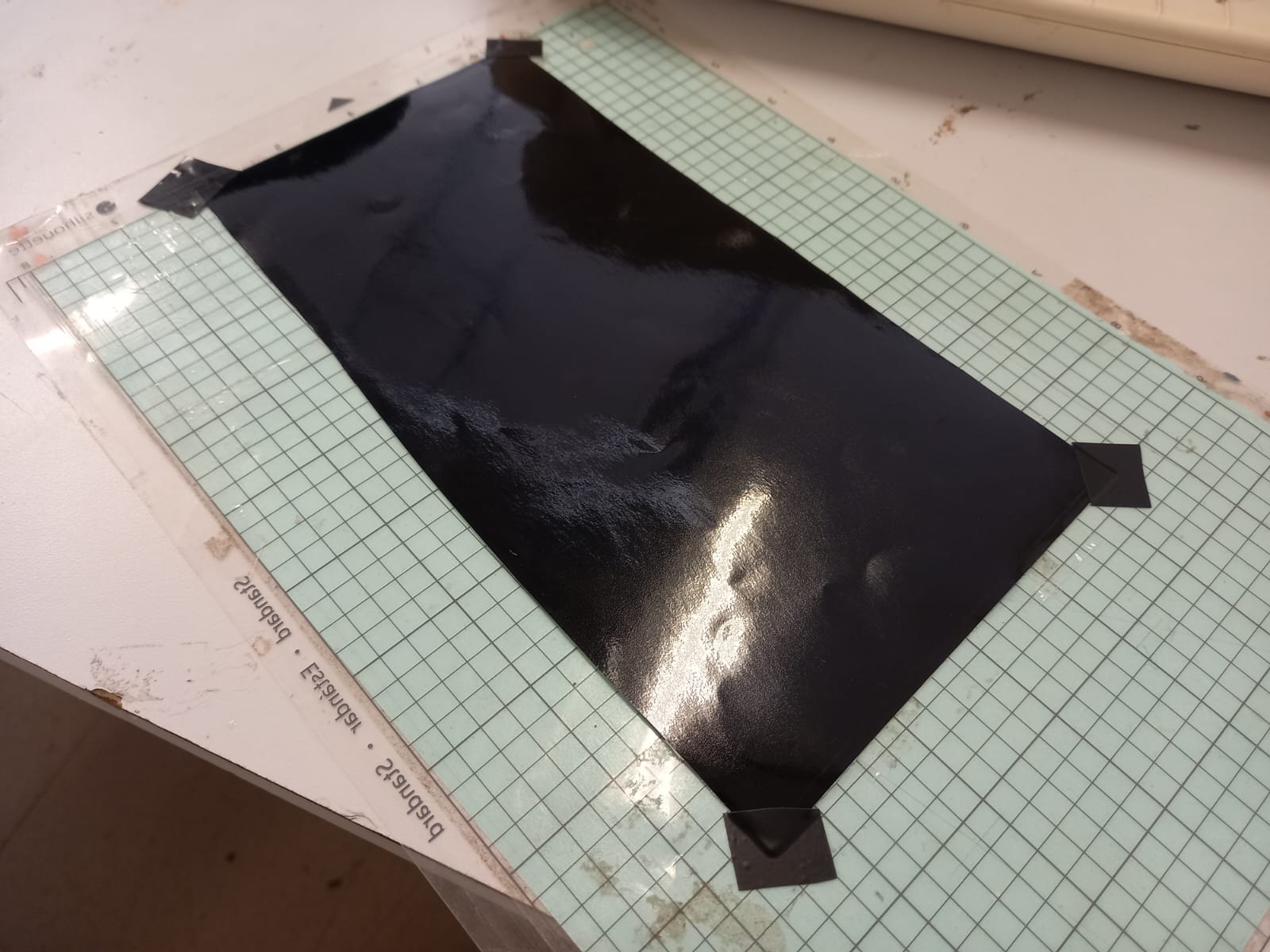
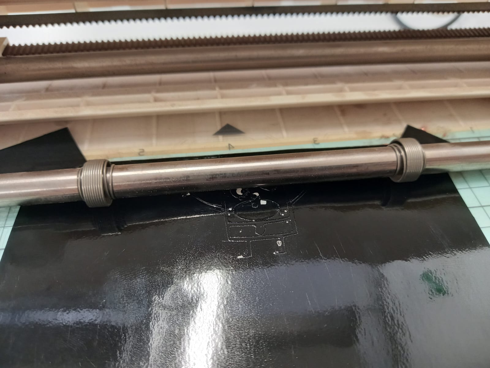
Prepare your vinyl by securing it with tape to the gridded or cutting board of the machine.
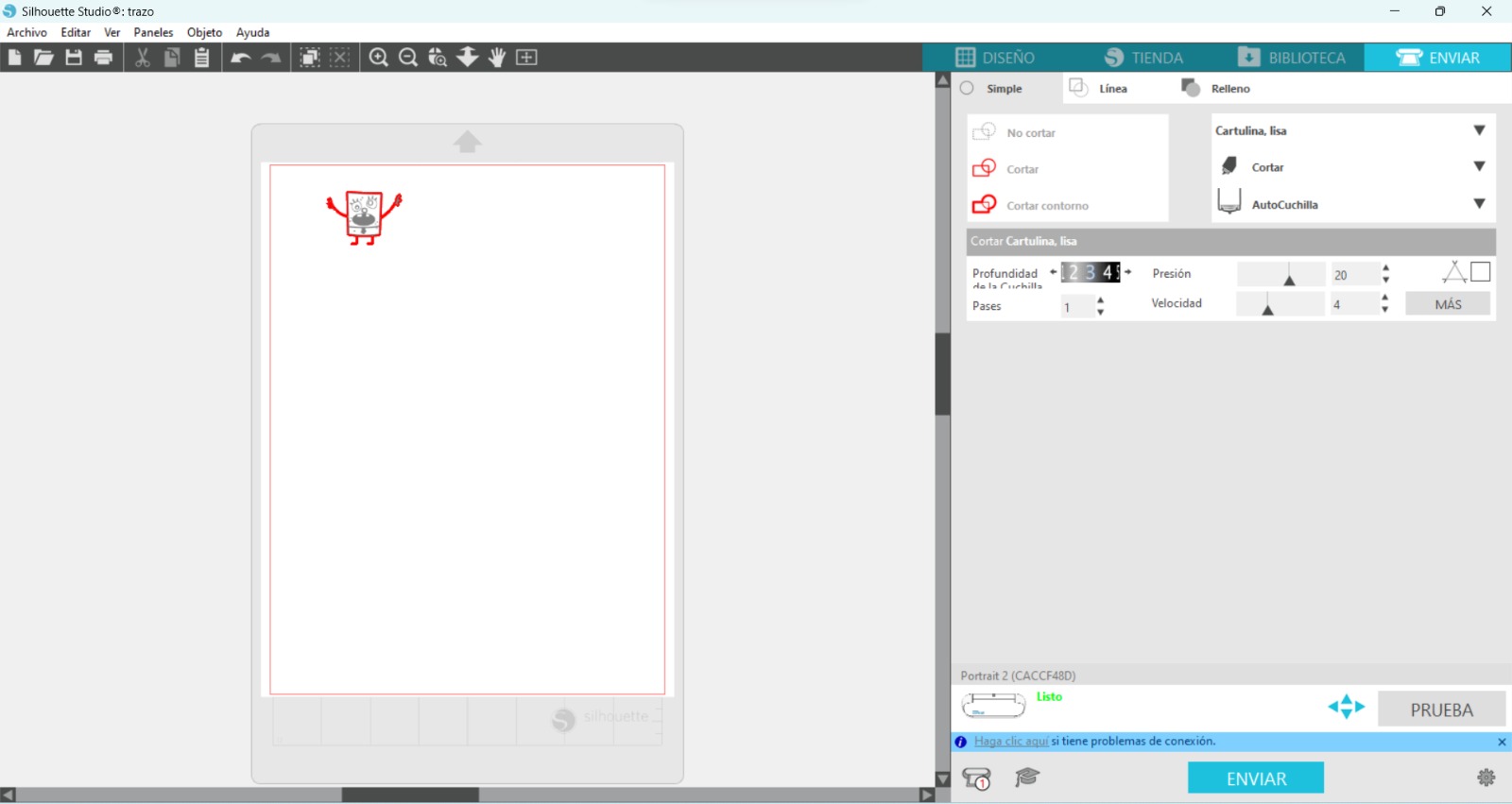
Click on Send/Enviar tab, the software only recognize the shape outline. The parameters I follow are blade depth "3", pressure "20", passes "1" and speed "4". If you are ready to cut, select "Send".
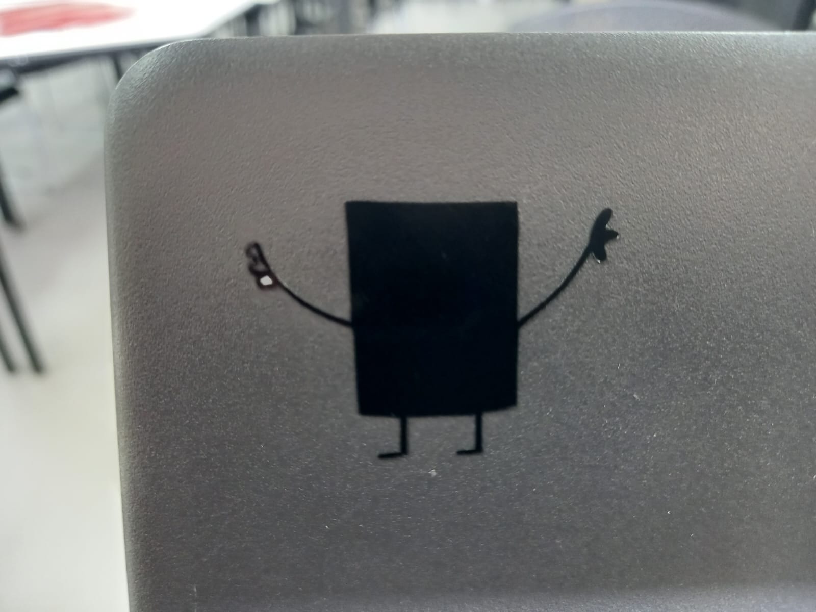
Ready! We have the sticker; paste it wherever you want.
Corrections
I realized that I hadn't cut the design correctly because I didn't prepare the image properly. So, select the sixth option, "Trace," from the options bar on the right.
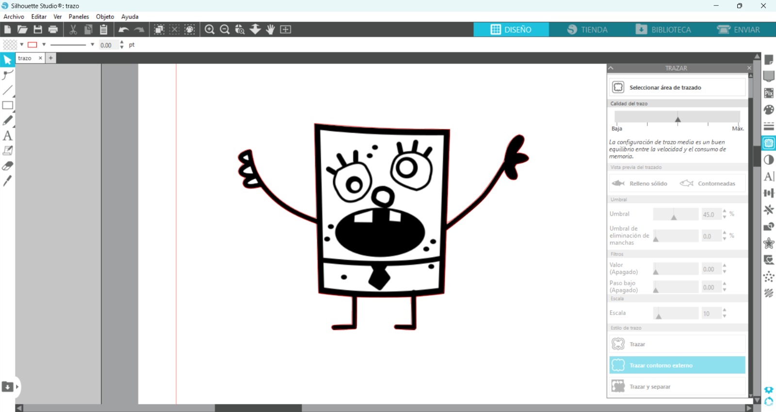
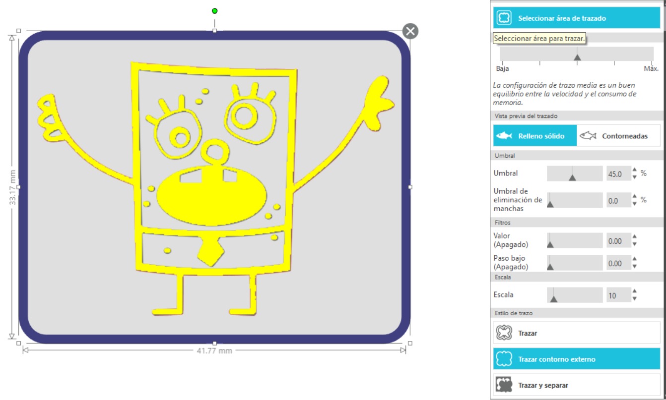
Next, select the tracing area.
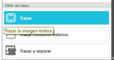
Choose "Trace the entire image" in the tracing style.
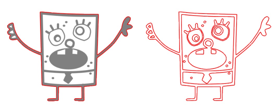
As you can see in the image, there's a clear difference. On the left, only the outline of the image is selected, so it will only cut the edge. On the right, all the internal contours are selected, which will allow us to get the cut we need.
Don't forget that the interface shows the size of the cutter's sheet, so position your image correctly to ensure it fits on the vinyl.
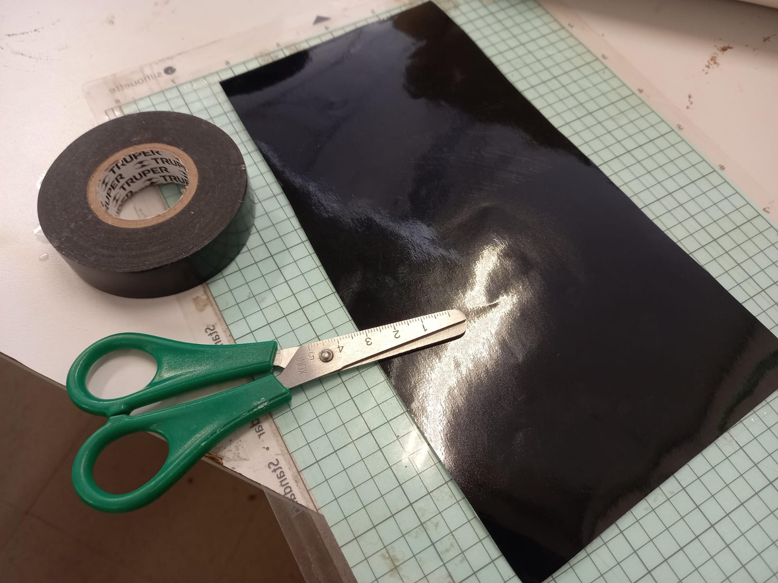
Preparing the vinyl is very easy. You only need scissors, tape, the vinyl, and the cutting mat. Tape the vinyl to the cutting mat.
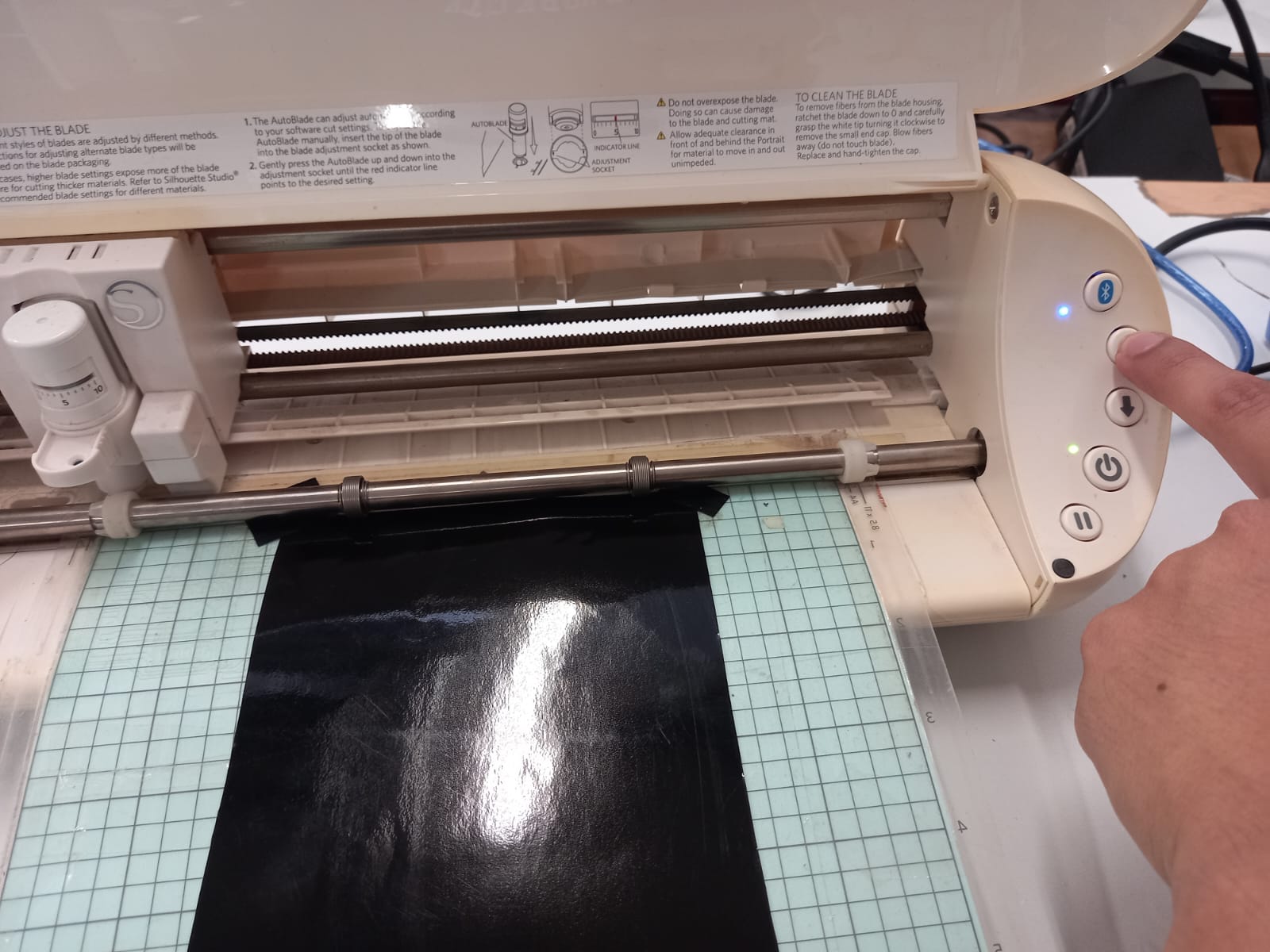
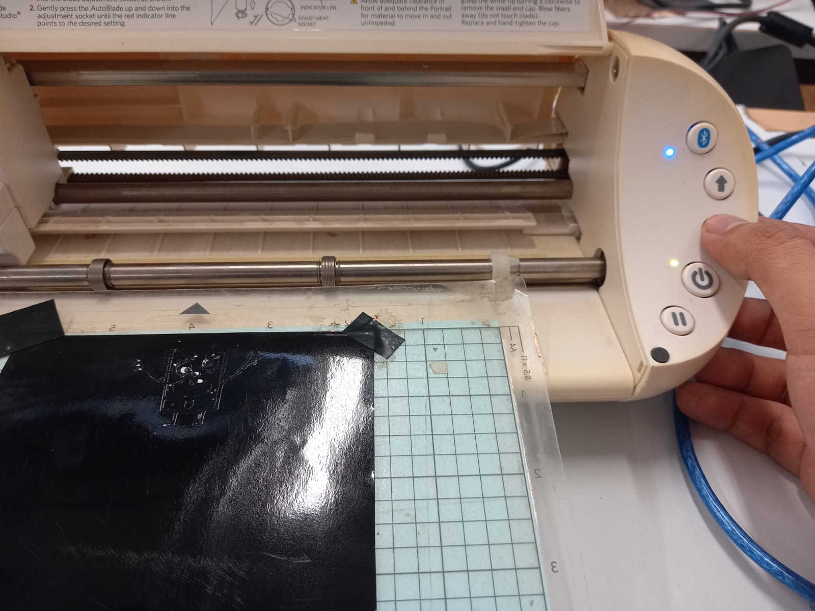
Once it's taped, place the cutting mat in the machine and press the button with the upward arrow. This will position the vinyl sheet correctly for cutting. Select "Send" on the Silhouette Studio App (as we made before) to start the cut. When the cut is finished, press the button with the downward arrow to eject the cutting mat.
You can carefully remove the cut with tweezers to avoid damaging it and then stick it on carefully.
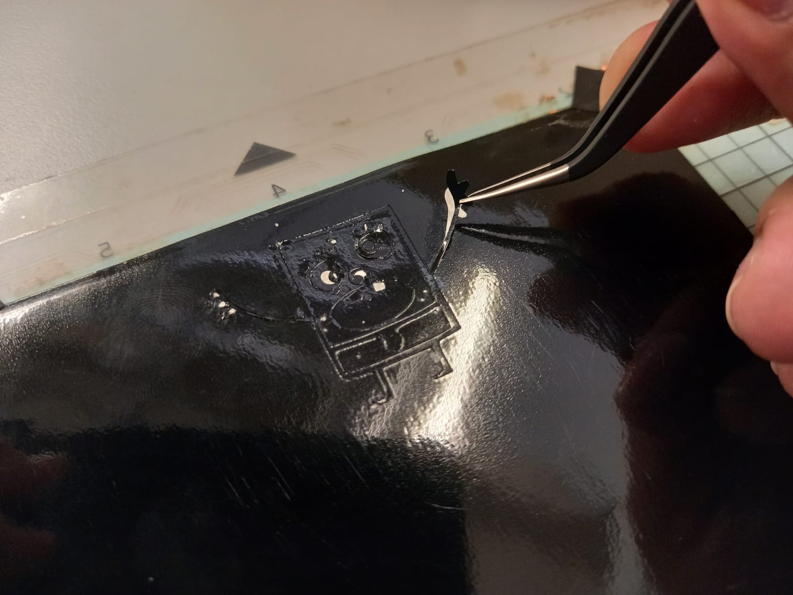
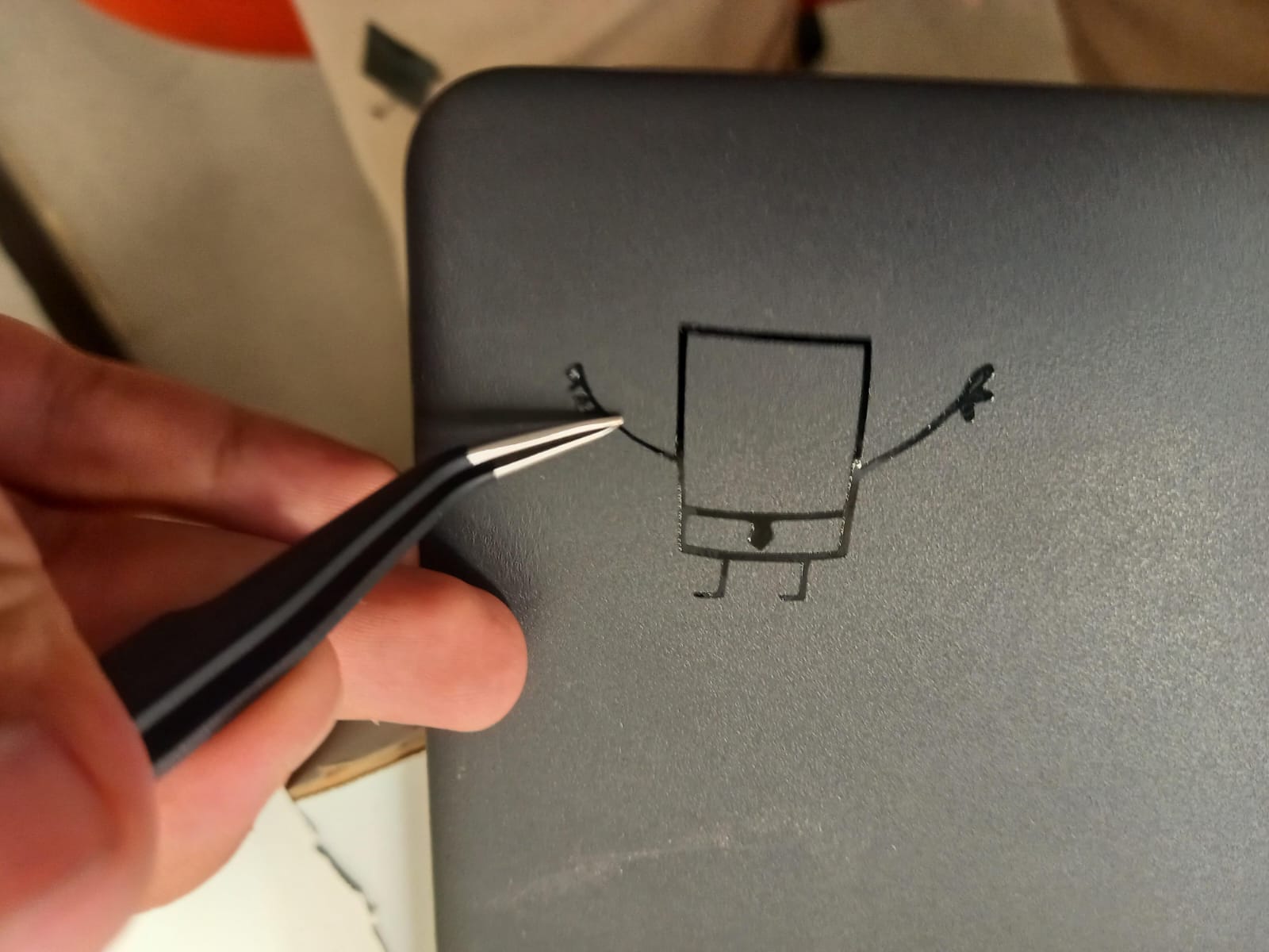
The dots were very tiny so didn't cut properly, and I had to improvise. However, it definitely looks much better and more kawaii! Haha
Files
- Making0 piece
- Making1 piece
- Making piece
- MakingA piece
- MakingB piece
- Making 3D Assembly
- Making Drawing
- Making DXF
- Doodlebob