2. Computer Aided design
This week I worked on designing a 3D model and 2D design. I utilized solidworks and inkscape
But we need more context, what design programs exist?
3D Modeling Software Comparison
| Feature | SolidWorks  |
CATIA  |
Fusion 360  |
Rhino  |
|---|---|---|---|---|
| Platform | Windows | Windows, Unix, Linux | Windows, MacOS | Windows, MacOS |
| Cost | $3,995 + $1,295/year | Custom pricing (usually $11,200/year) | $495/year | $995 |
| Usability | Easy to use | Complex | User-friendly interface | Intermediate |
| Industry | Engineering, Manufacturing | Aerospace, Automotive | Product Design, Engineering | Architecture, Industrial Design |
| Parametric Modeling | Yes | Yes | Yes | No |
| Simulation and Analysis | Integrated | Advanced | Basic | No |
| Cloud Collaboration | No | Yes | Yes | No |
| Plugins and Extensions | Wide variety | Limited | Limited | Wide variety |
| File Compatibility | High (STEP, IGES, etc.) | High (STEP, IGES, etc.) | High (STEP, IGES, etc.) | High (STEP, IGES, etc.) |
| Learning Curve | Moderate | High | Low | Moderate |
| Features | 3D CAD, Simulation, PDM | 3D CAD, PLM, CAM | 3D CAD, CAM, PCB Design | 3D CAD, Scripting, Surface Modeling |
| Rendering | Yes | Yes | Yes | Yes |
2D Drawing Software Comparison
| Feature | Inkscape  |
Adobe Illustrator  |
CorelDRAW  |
|---|---|---|---|
| Platform | Windows, MacOS, Linux | Windows, MacOS | Windows, MacOS |
| Cost | Free | $20.99/month | $499 (perpetual license) |
| Usability | User-friendly interface | User-friendly interface | User-friendly interface |
| Vector Support | Yes | Yes | Yes |
| File Compatibility | SVG, PDF, EPS, AI | AI, SVG, PDF, EPS | CDR, AI, SVG, PDF |
| Design Tools | Comprehensive | Advanced | Advanced |
| Learning Curve | Moderate | Moderate | Moderate |
| Updates | Regular | Frequent | Regular |
| Integration with Other Software | Limited | High | Moderate |
| Support and Community | Active (Open Source) | Extensive | Extensive |
| Features | Vector drawing, Bitmap tracing | Vector drawing, Typography | Vector drawing, Page layout |
| Rendering | No | No | No |
This week I worked on designing a 3D model and 2D design. I utilized solidworks and inkscape
3D Model
Mouse tips
- Pressing scroll -> rotate view
- Pressing scroll + holding right click -> roll view
- Ctrl + (0 - 7) -> views orientation
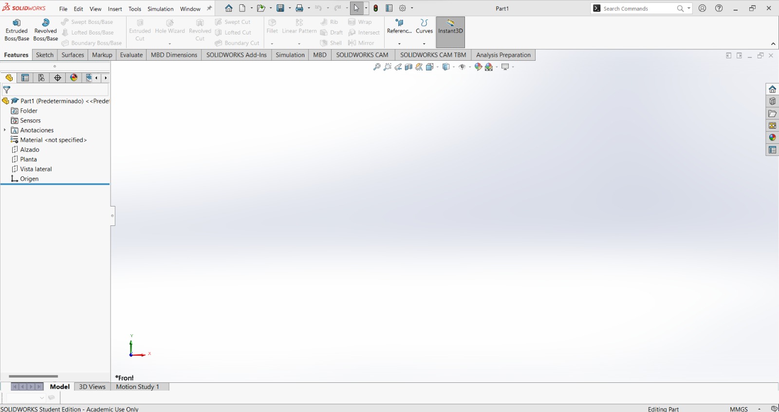
Open solidworks and select Part
This is the main panel.
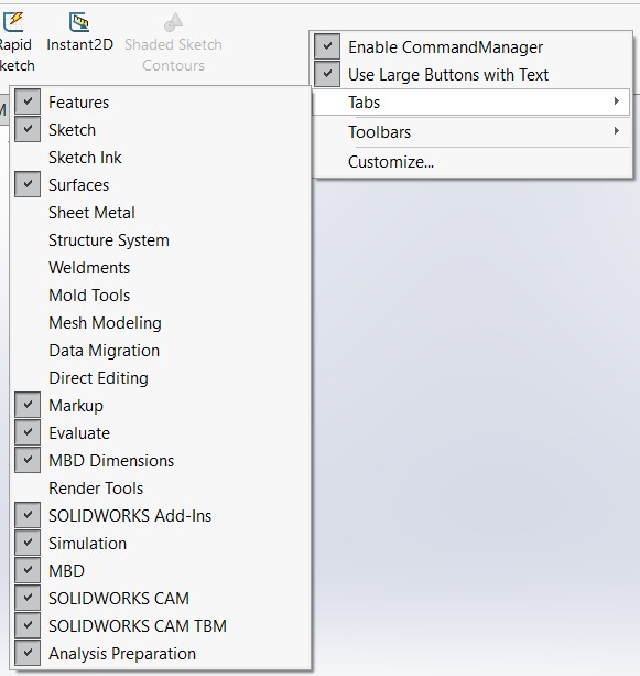
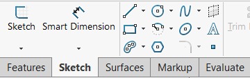
Ensure that the surface option is enabled by right-clicking on the operations bar (red circle) -> Tabs -> Surfaces.
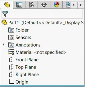
Choose any plane: Front plane - Alzado Top plane - Planta Right plane - Vista lateral
Click on the sketch tab.

Next, we will explore and experiment with some features.
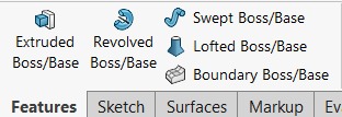
Extruded boss/base
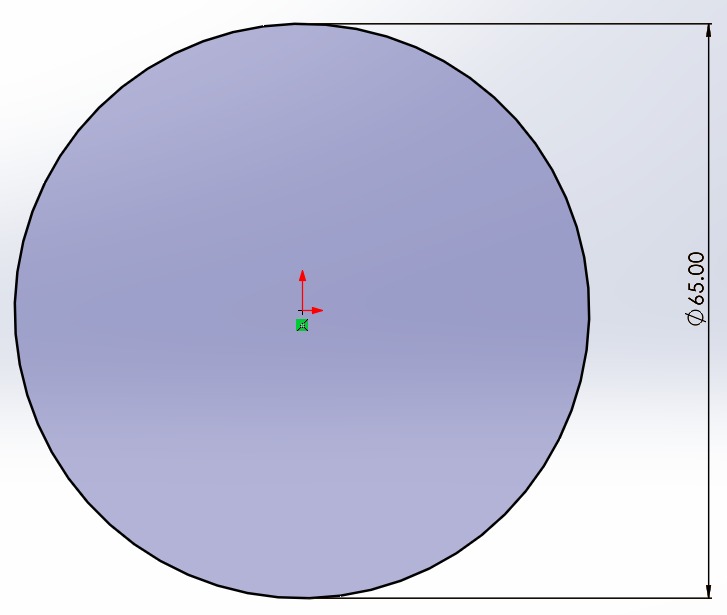
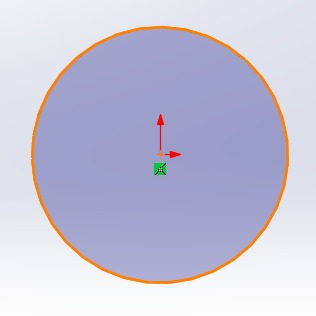
Draw a circle
Pro tip: I suggest starting your drawing by clicking at the center to prevent any issues with symmetry or dimensions later on.

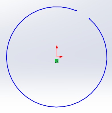
A properly drawn figure will have a black outline and a gray fill, signifying that it's a closed shape, enabling the creation of solids/volume. Otherwise, it will be displayed with a blue dot. As shown below:
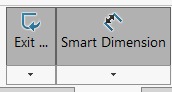
Click on "Smart Dimension"
Select the outline of the shape.
Provide a measurement in the units of your preference.
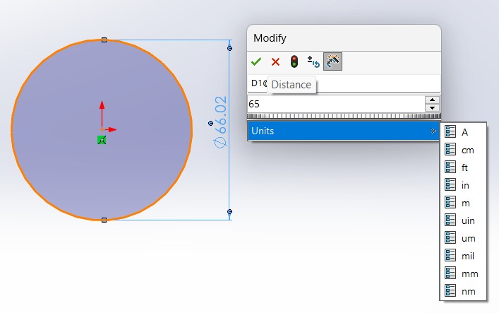
Exit the sketch.
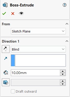
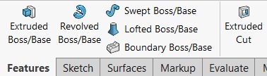
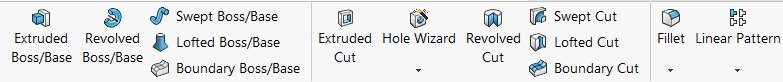
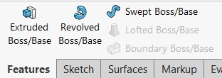
Choose extruded boss/base tool.
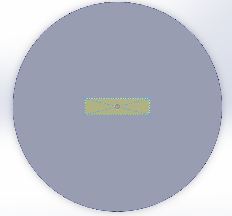
If you don't see this figure in yellow or encounter problems, it probably stems from having open contours or incorrectly defining (providing measurements for) your shape. To identify the error, it's helpful to select and drag/move the figure.
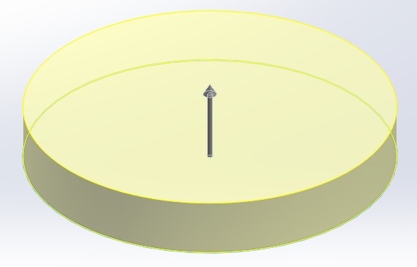
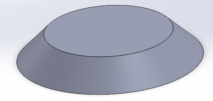
On the left, you'll see various options. In this guide, we'll take specific steps to create a shape, but feel free to explore the options. Remember, if something doesn't go as planned, you can use Ctrl + Z to undo the last modification. Once you feel confident about your changes, click on the green checkmark.
Oops, something went wrong... on purpose haha
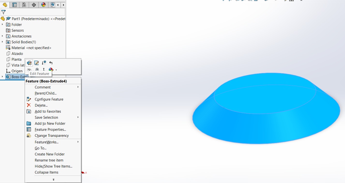
Or something didn't go as planned, you have the option to right-click on the recently created feature and select "Edit Feature." The shape to be modified will be highlighted, typically in blue. Proceed to make edits to your shape.
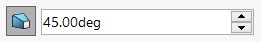
This feature enables us to create angles into our shapes. Set it to 0 degrees.
Extruded cut
Sketch a rectangle and click on the solid to draw.
I used the centered rectangle and provided measurements with smart dimension. This tool can measure sides, from side to side, vertex to vertex, angles, and other parameters.
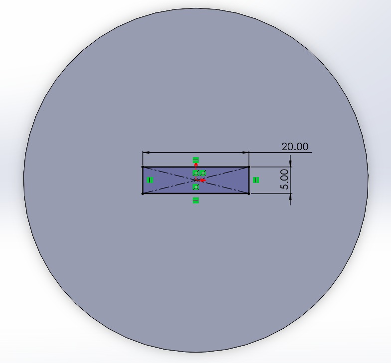
Important: If you no longer want to draw a line, press the Esc key. Exit sketch -> Features -> Extruded Cut. Remember, the shape must be selected.
Explore the options; typically, "Up to Next" is used, but each has incredible uses.
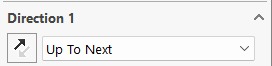
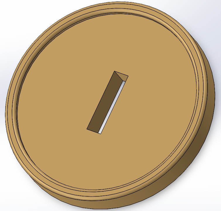
Awesome, looks like a Mario Bros Coin
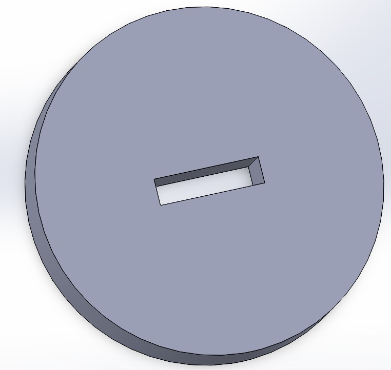
Now, much better. The "Blind" option provides measurement for the cut
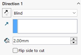
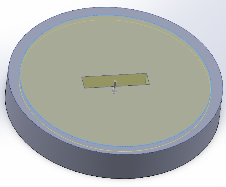
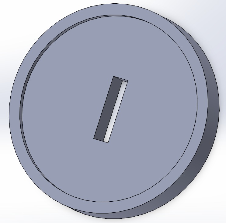
Mmm, could be better...
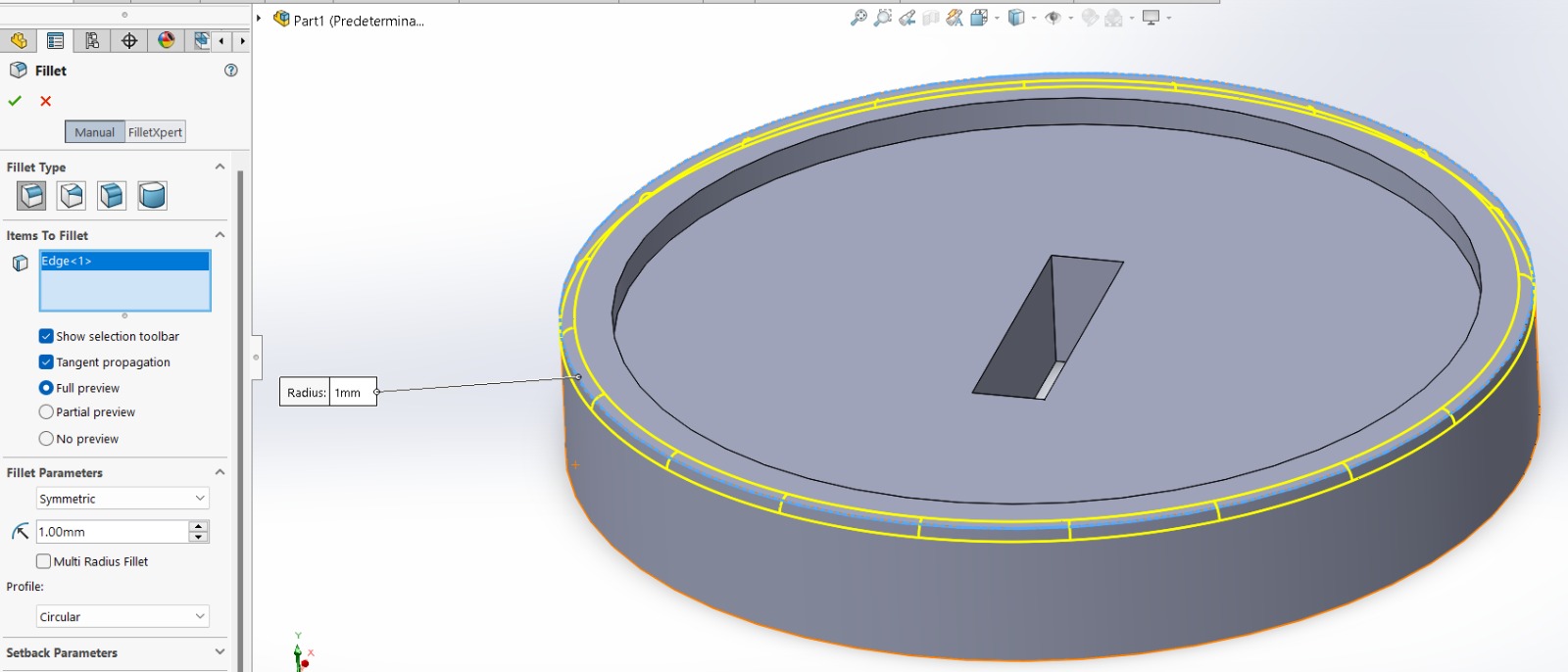
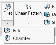
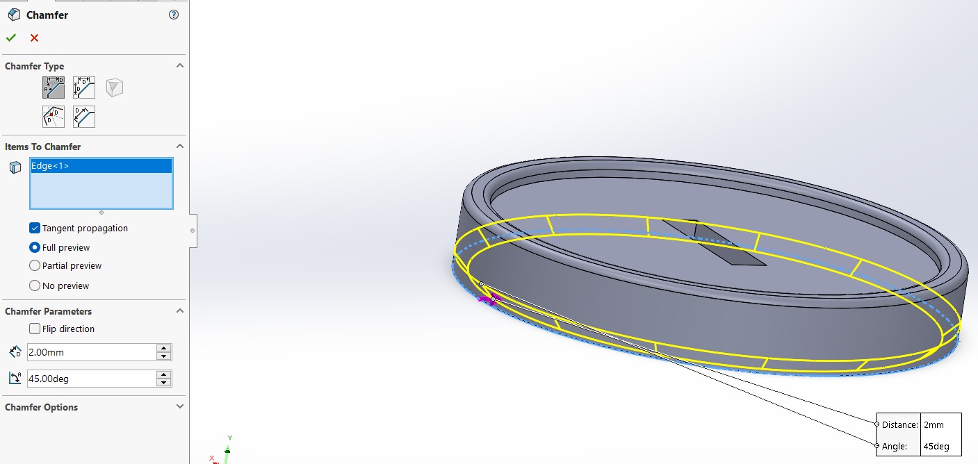
Fillet and Chamfer
Click on fillet option
Select Constant Size Fillet option (First icon) and the outline you want to round.
Chamfer option is used to make straight cuts in the solid
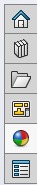
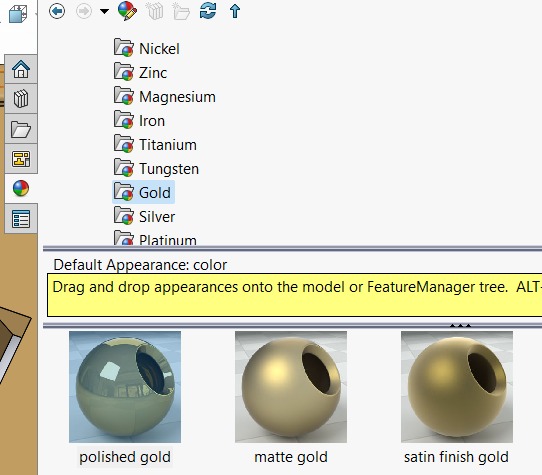
Confirm the changes (green checkmark). On the right side, you'll find these options; choose the color sphere. Select the appearance you prefer for the coin and drag the material onto the solid. Click on Add Appearance.
Perfect! If you want to view the material with higher definition, you can render the image.
Render
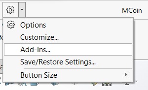
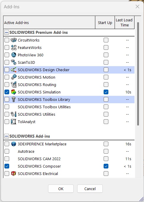
To render, we go to the gear icon and expand the options. Click on Add-Ins.
Activate the PhotoView 360 option.
The Render Tools option will be added to the Toolbar.

Select Edit Scene
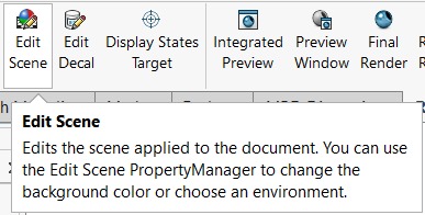
And choose one.
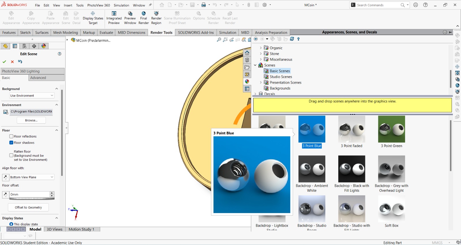
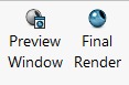
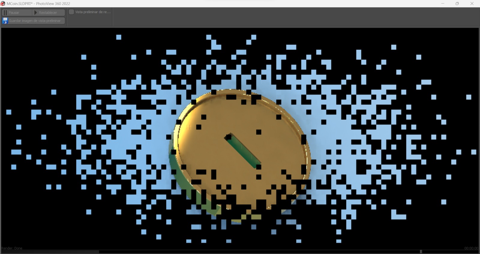
Then select Preview Window or Final Render depending on what you like.
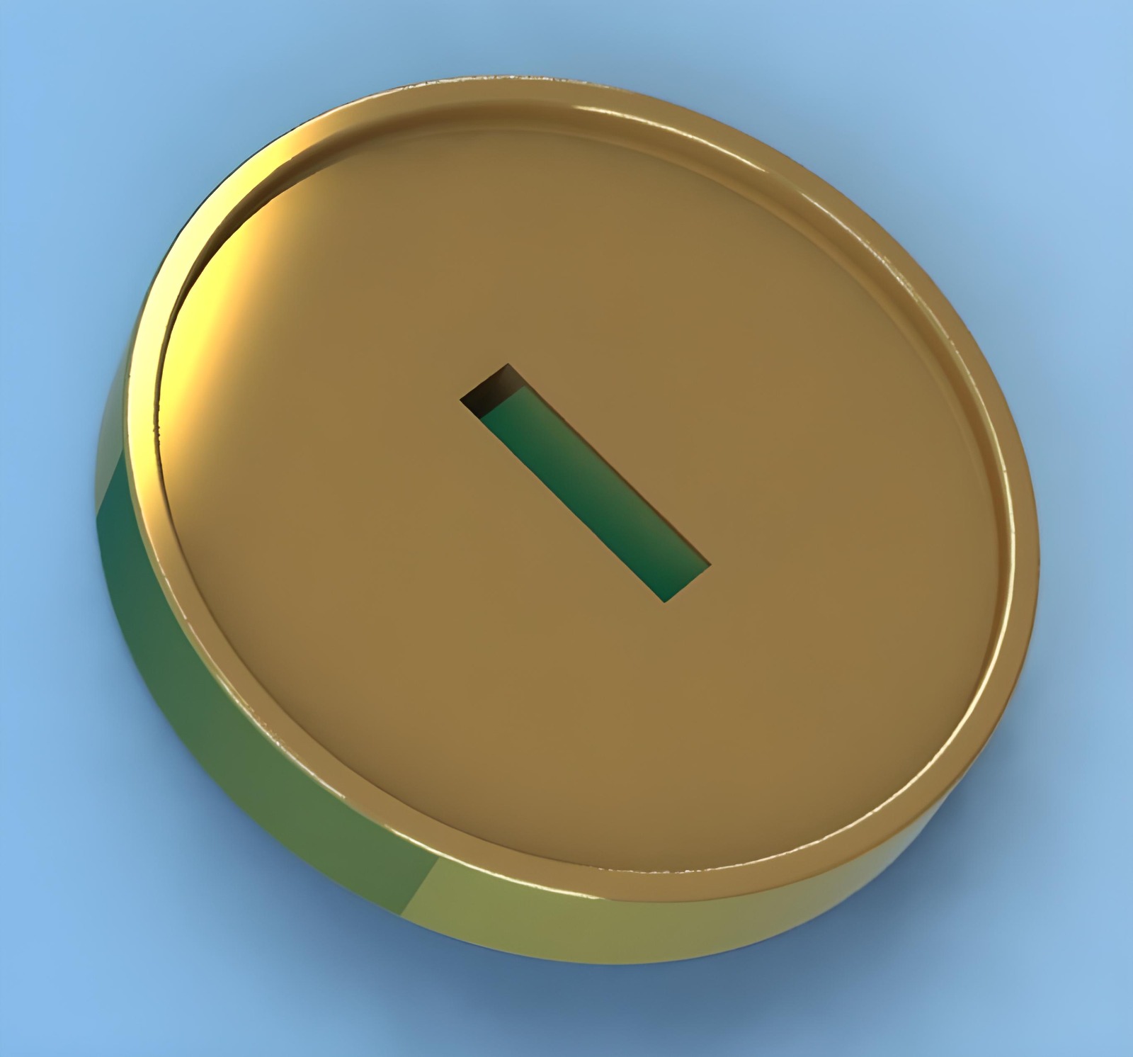
The Render
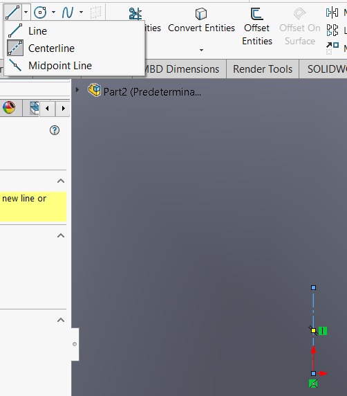
Revolved
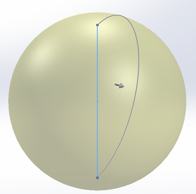
Open a new cat part, choose a plane and sketch there a semi-circle. In my case, I used the center point arc tool and also drew a connecting line to this arc
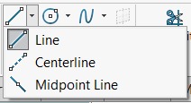
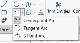
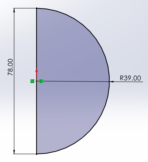
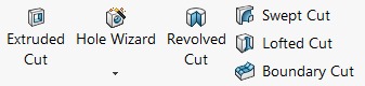
In features menu, select Revolved boss/base and the outline shape
Straight line will be the axis of revolution since we can't select curved lines as the axis.
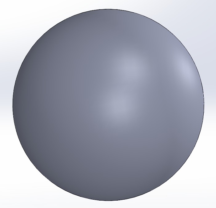
We drew a sphere
Click on front plane and make a sketch
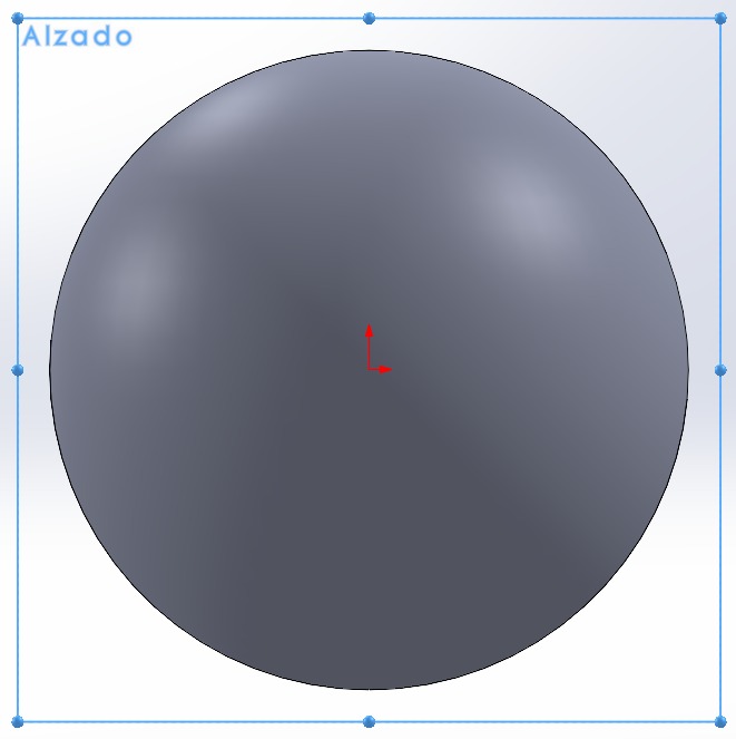
Using the blue centerline as a guide, draw a square.
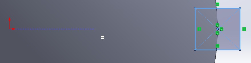
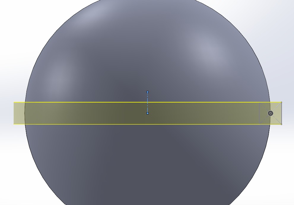
Trace a centerline.
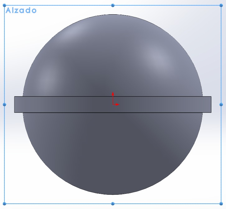
Use revolved feature.
Cool, looks like a lollipop or a planet! Draw another sketch.
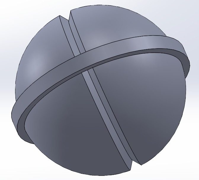
Draw a triangle and a centerline (reference axis).
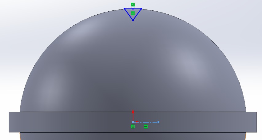
Select the triangle and axis, then apply revolved cut feature
Now, we have a 3D smash ball from Nintendo game.
2D Design
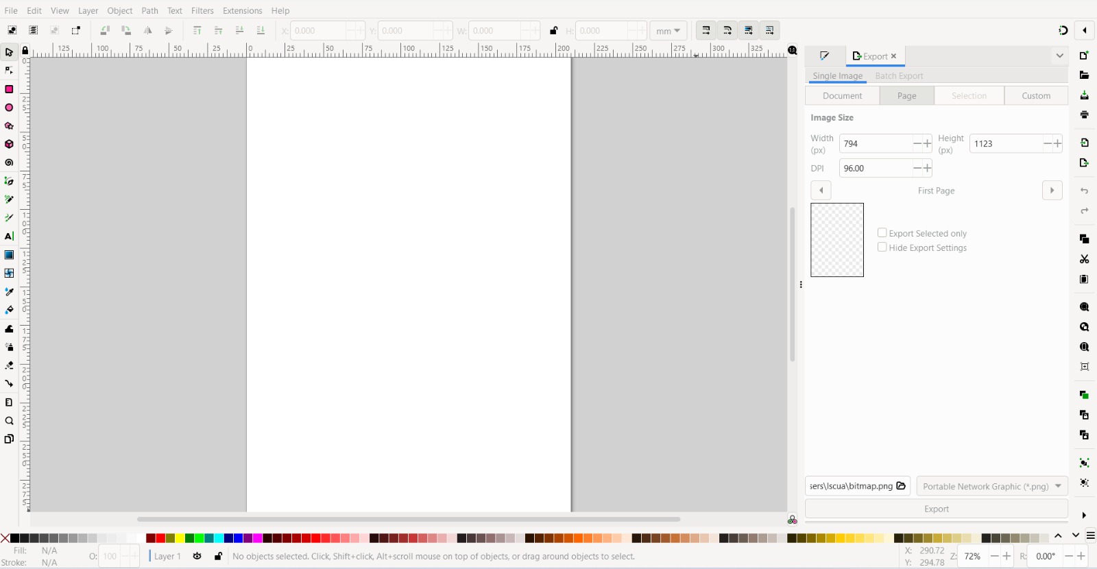
For 2D drawing, Inkscape is a great free software.

This is your main interface
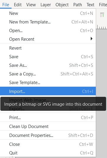
Let's trace an image that I made in Canva. To do this, click on the File tab and import a file.
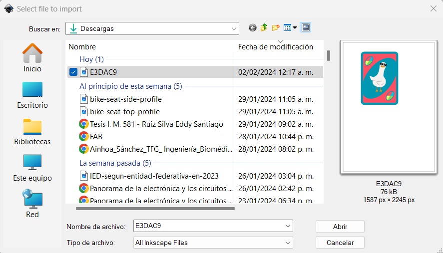
Select and open the file.
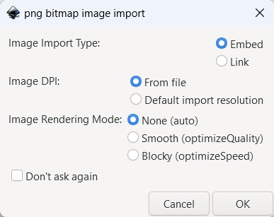
Default options are ok, for this time
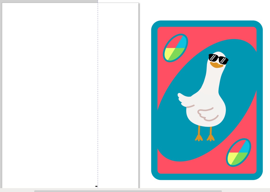
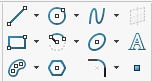
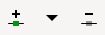
Draw a square or a rectangle by pressing R key or selecting its icon on the left side.

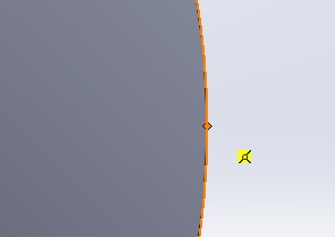
Adjust the nodes from rectangle/square to round out its corners. You can press N key or selecting icon node.

They can be identified as white dots or small diamonds located at the corners.

Select your figure and pick colors from wild card imagen pressing this icon or D key.
Also, you can fill bounded areas (U) and select your figure.
If your rectangle is dublicated, don't worry, you can delet it.

Beizer tool it's useful to make organics lines shapes.

I suggest initially using straght lines, and later, whit the node tool, you can give them shape.

In case you forget a node, no need to worry; you can add or remove them using the following options.
This toolbar, you cand adjusting curvature to the straight lines.

You can manipulate the node directly or take the line and give it curvature directly. If you choose the first option, then select the node and afterward the third option to generate the curvature lines. Play with the options:
- Asymmetrical curve
- Smooth curves
- Symmetrical curves
- Automatically generated smooth curves

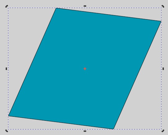
After all copy color from the shape. Oops the original rectangle is bigger than our rectangle.

When the arrows are in this orientation, it indicates expansion of the image. Press Ctrl to ensure the modification is Symmetrical.
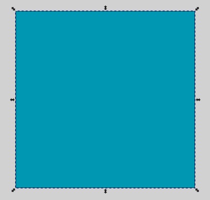
Select the shape again and the arrows will change. In this orientation, it is for rotating or tilting.
Oh, when moving the image, its position changed.
These options move the position of the shapes.
And these options rotate it in a easy way.


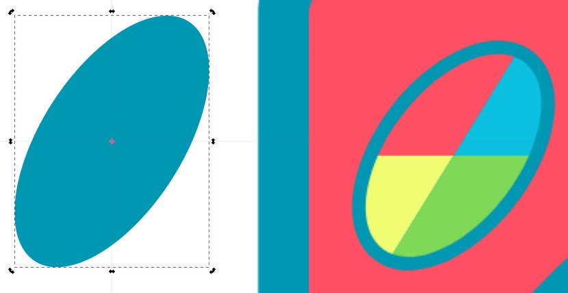
Next, copy the other shapes using the bezier tool and the features we have learned so far. Draw a circle (E) and rotate it.
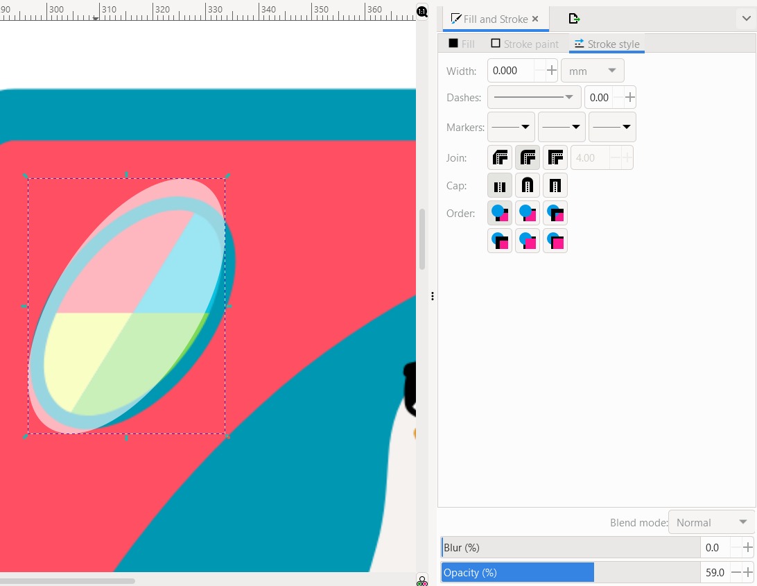
All modifications which you have made are on the right panel. Here you can find opacity option.
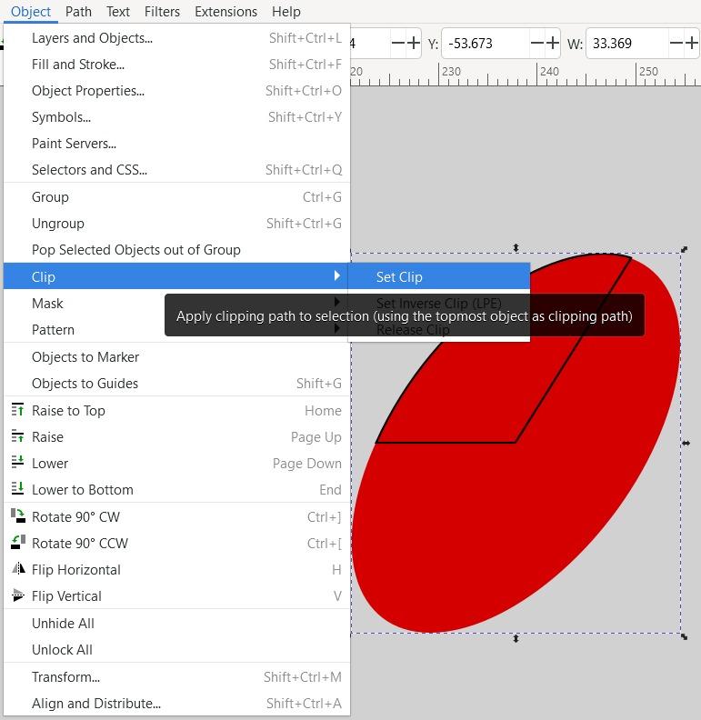
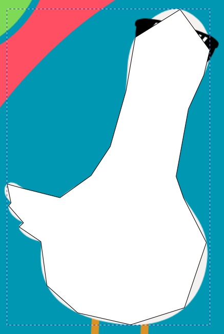
To define the colors of the wild icon, I sketched the part I want to cut. We select both figures by holding down the Shift key.
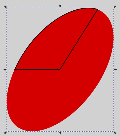
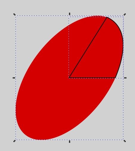
Cut in the following way: Object -> clip -> set clip.
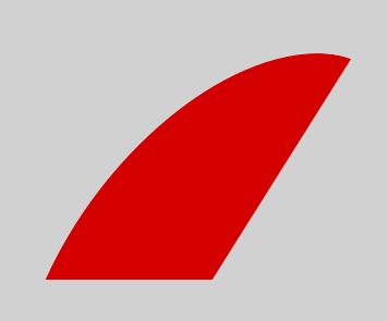

We give them color, select them and use the command Ctrl + G to group.
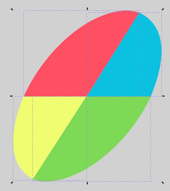
Group all wild shapes.

Looks awesome!
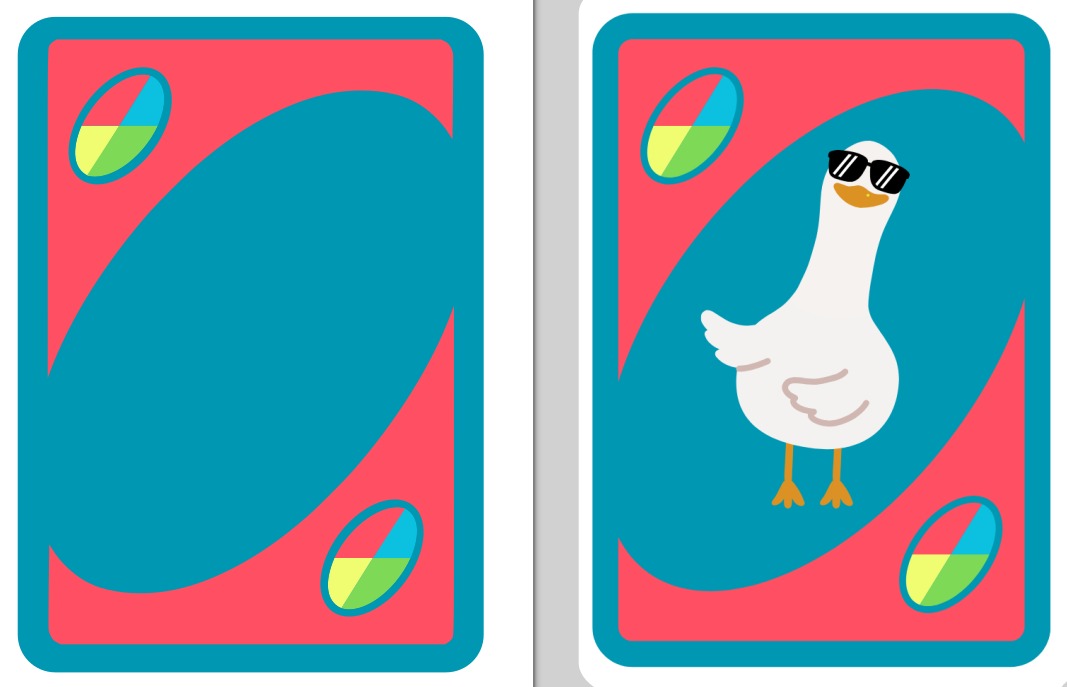
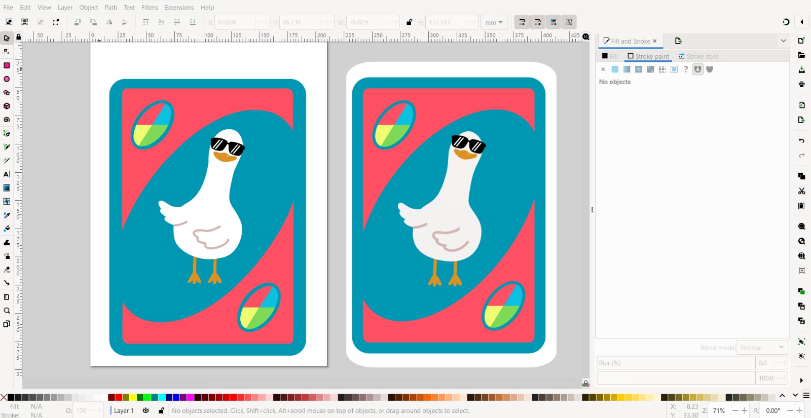
Time to draw the cool duck.

In the right-side panel, select "No paint" for stroke paint to remove the black outline.
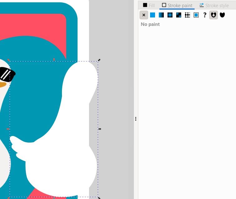
Looks like a meme haha

"Heaven must be missing an angel"

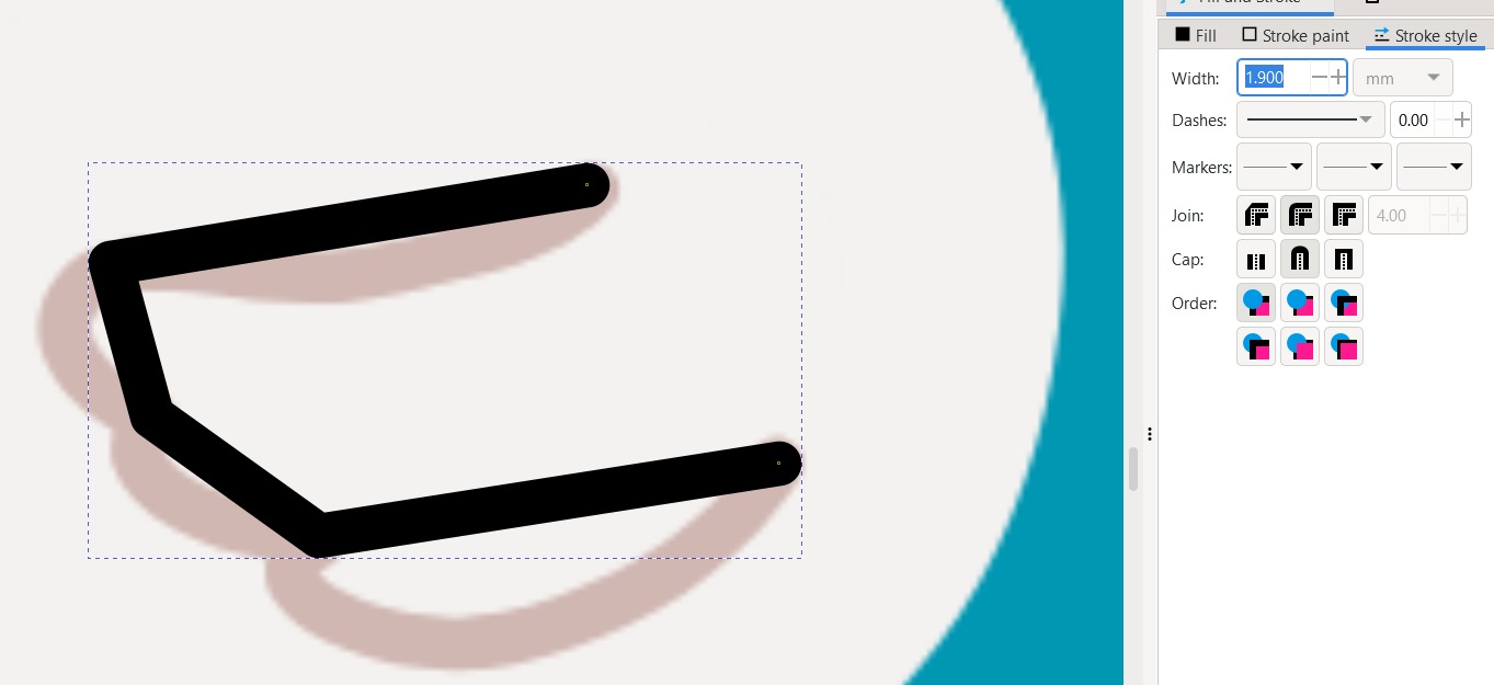
You achieve the wing by making the bezier line thicker.
Done! Like two drops of water. On the left is the vectorized image we have made, and on the rigth is the image I created for this example in Canva.
Thank you!!
Conclusion
I have used Catia, Solidworks, and Fusion360 for 3D modeling. In the end, I decided to showcase the use of Solidworks on my page because it is very intuitive. It shows you why there is an error and how you can correct it. Although, there is a feature in Catia that I miss in Solidworks, as the latter does not show open points in a sketch. However, this is somewhat irrelevant when you already have experience designing. Furthermore, when searching for opinions online, I found that many users prefer Solidworks for its intuitive interface and its ability to solve problems clearly and directly. Additionally, the online community is very active, and I can always find answers to my questions quickly. On the other hand, although I liked Fusion360 a lot for its ease of creating organic-shaped parts, I found that some users on blogs and social media expressed difficulties with its learning curve. It has many powerful features, but its interface can be overwhelming for beginners. It took me a long time to get used to it, and I still feel like I'm not fully utilizing its potential. And despite being free licensed, its dependence on an internet connection can be inconvenient.
For 2D software, I feel there are many tools that make the task easier; however, Inkscape is a great option to start with. Among the standout features of Inkscape are the creation of shapes and vector objects, editing strokes and curves, creating special effects, importing and exporting files in a variety of formats, and much more. It is easy to use, its interface is clean and understandable, there are many tutorials available on the internet, and there is a large community willing to help and provide tips. You can even generate G-codes! It's incredible, although I'm not opposed to the possibility of using other 2D design software in the future.
Files
- Coin solidworks
- Ball solidworks
- Base centrifugal spinning
- Syringue pump
- Cool duck.png
- Cool duck.svg
3D Model
2D Design
I prefer to give you a nice desktop image