Computer-Controlled Machining
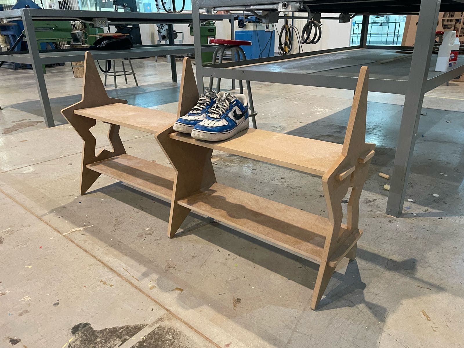
This week's assignment is called: Computer-Controlled Machining. Which consist in designing something in the CNC with assembly without using any kind of glue!
Team Practice
Link of our team practice.
Materials
- MDF Board - 1200 x 2400 mm and 15mm thickness
- Drill tool for the CNC machine - 6.35 mm diameter
Sketches
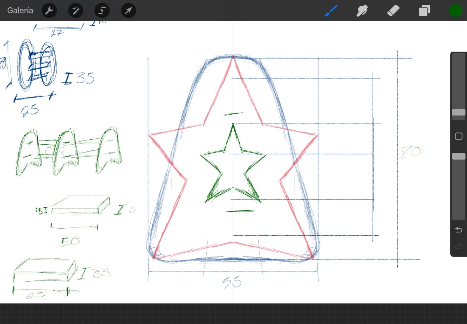
I right away knew I wanted to do a shoe rack, for me to have in my room and use. With this in mind, I head over to Procreate to start my sketching process: Here I have different measurements that I needed to complete my piece, taking always in consideration my MDF board measurements, also in the middle left I drew what the finished piece would look like without the star shape.
AutoCAD
Once I had a visual representation of what I wanted, I proceeded to open AutoCAD for the creating of all the pieces I needed. I choose AutoCAD because of the accuracy that I needed for my project, since all the assemblies had to fit into each other. Using the line, trim, offset and splice tools to create the shapes and pieces. I will explain all the shapes:
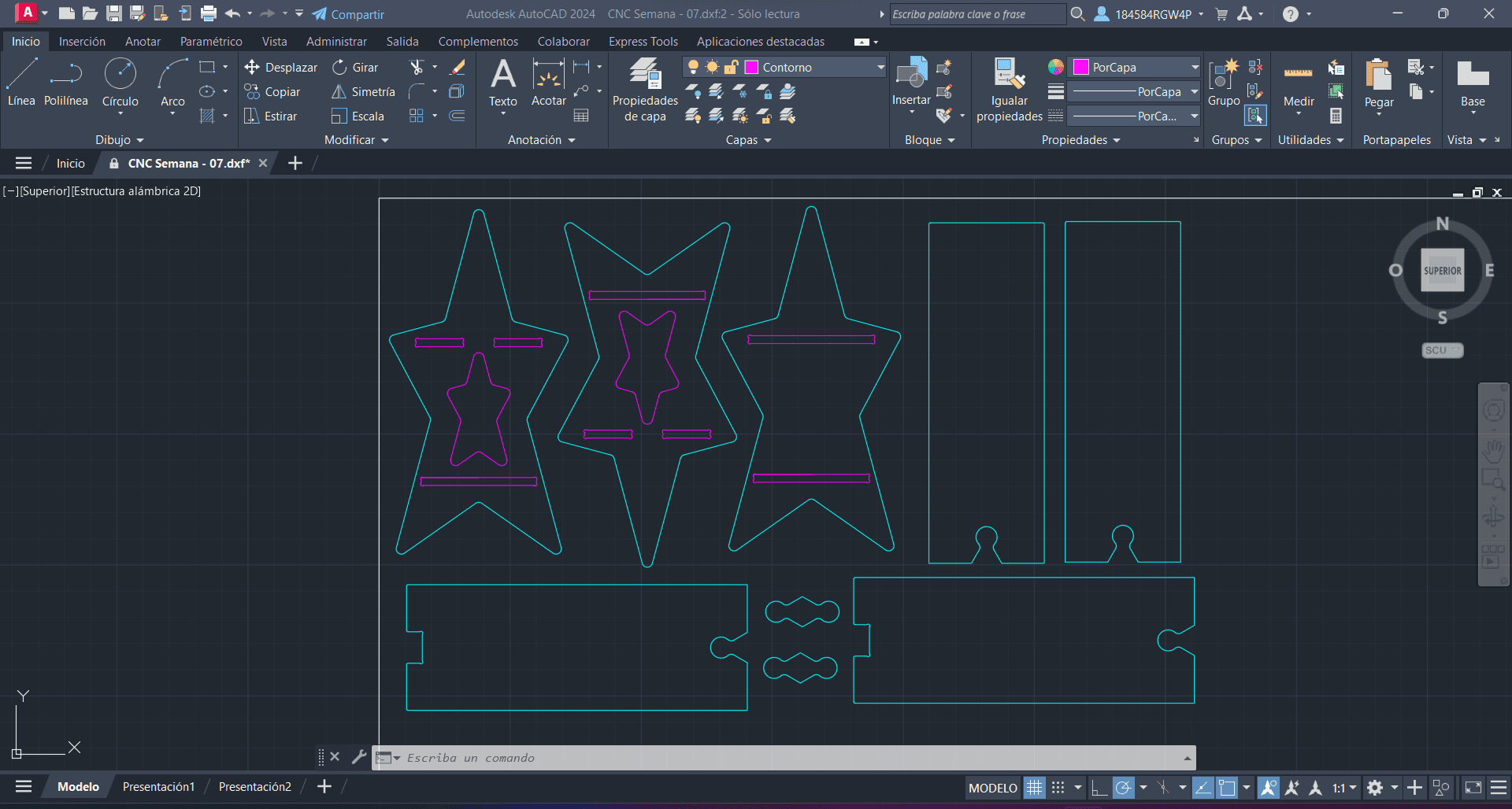
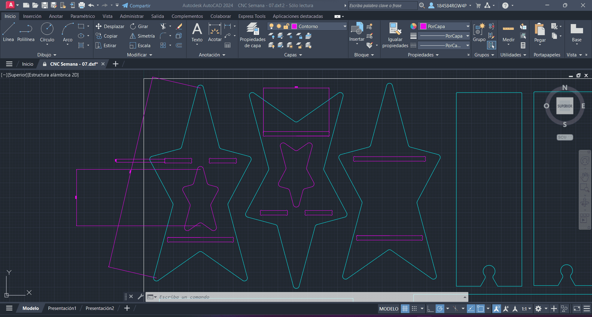
The stars are the main pieces in my shoe rack, they measure 65cm tall, and 35cm wide. The star in the inside is 19cm tall, you can see the two different colors in the stars, the inside cuts and the exterior ones, this is basically how the machine is going to read those lines, the pink lines are going to be interior trajectory, this will make sense once we are inside VCarve. The assembly measurements correspond to the material thickness, which is 15mm. The two stars on the left are the ones on the sides, while the right one is the one in the middle. As you can see, I added a T-Bone fillets, so there's a smoother assembly in my piece, this have a 3.175 radius.
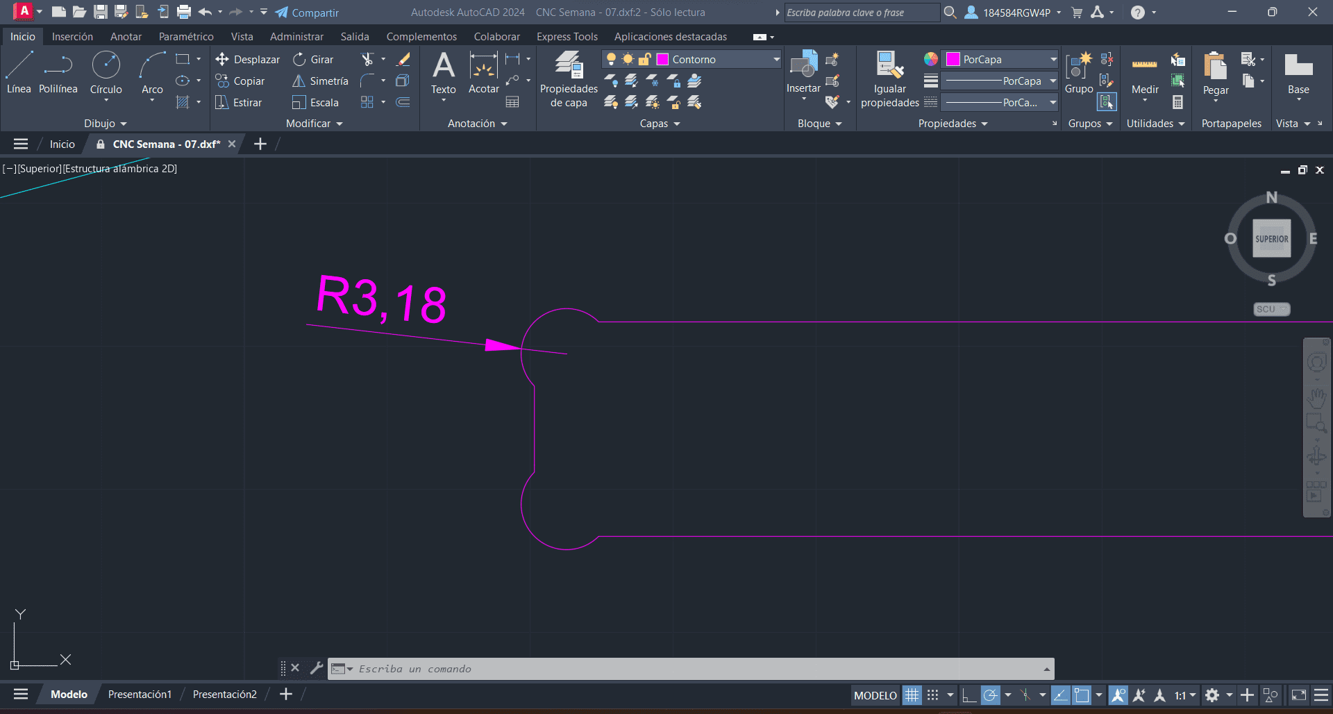
The boards are pretty self-explanatory, I had no space for the whole piece, so I decided to divide it in two symmetrical parts, joined by the "cookie" in the middle. I wanted to do this shape because of two main reasons: One, I like the shape, and two, the circles in the sides will help the two boards connect and stay in position for the whole piece to not fall. You can see the measurements in the pictures, but the boards are 650mm x 240mm.
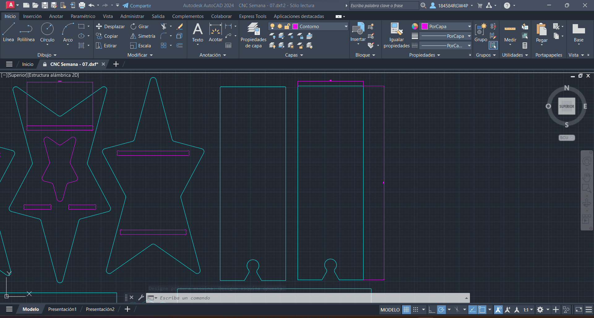
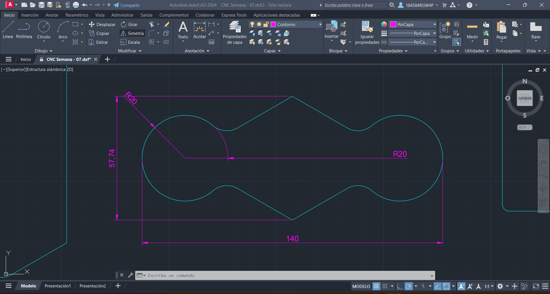
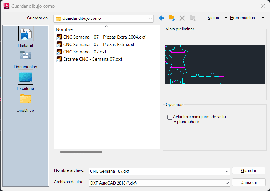
Once I had all done and in different layers for me to use, I just needed to export it as a DXF file.
VCarve
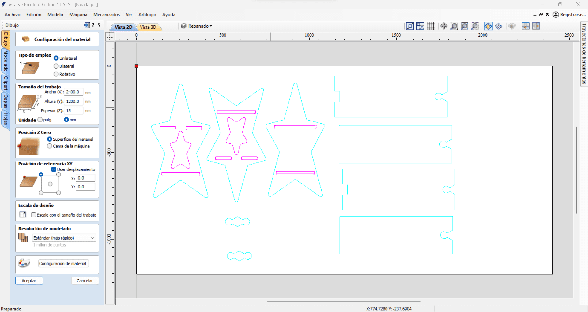
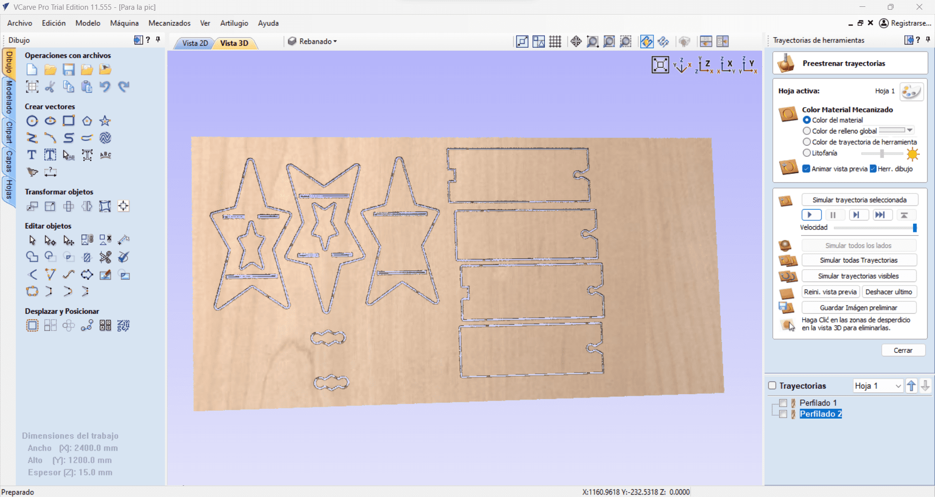
Now that we have our file, we can open it in VCarve and start to simulate the router cutting, first I needed to input the table dimensions, in this case, my MDF board, which is 2400mm x 1200m, it's also very important to specify the thickness of the material and the 0 position. Once we have that, we can start by using the "Tool path Profile" tool and start to give our End Mill specifications.
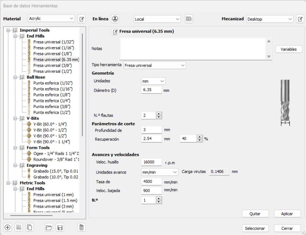
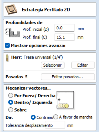
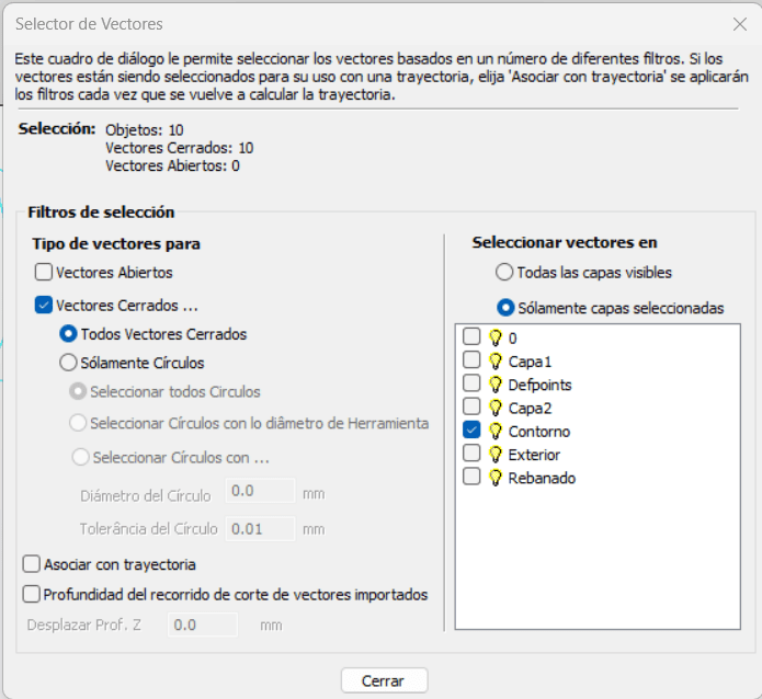
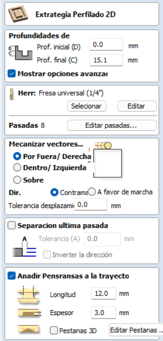
Because of the length and diameter of our tool, the number of steps it will take to completely cut is 5, this so each step is approximately 3mm deep. Also, I needed to do the inside cuts first, if I do them later, the pieces might move around and the cuts will be uncalibrated, so I choose the inside cut first. As you can see, the final deepness is 15.1mm, this is so the tool completely goes through the material and hits the sacrificial board underneath. Remember when I said I was doing everything in layers over in AutoCAD?, this is where that's going to be helpful, once I needed to select the objects for the cuts, I can simply go over the layers and select the layer where all the inside cuts will be and clic “calculate”.
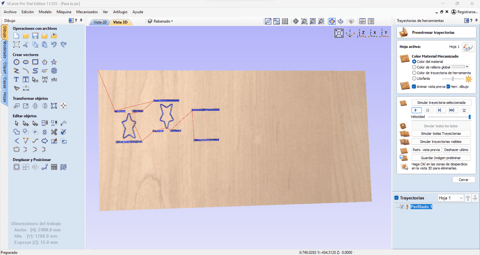
If I need reassurance for the cut, I can now head over to the 3D view, where the path we just created is going to show up on a board, and we can even see a simulated animation!
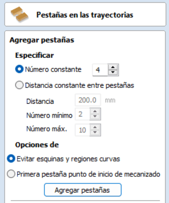
Now we just need to do the same thing with the exterior cuts, I changed the rotation of the tool and added some tabs along the perimeter of the pieces in order for them to stay in place once cut. I decided to make the tabs 12mm long and 3mm wide, placing 4 along all the pieces, the tabs will be the last thing the CNC does.
Once we calculate that, the Vcarve is done! I just need to save the file for the CNC to read, and save it in a USB file to transport it.
Cutting with the CNC
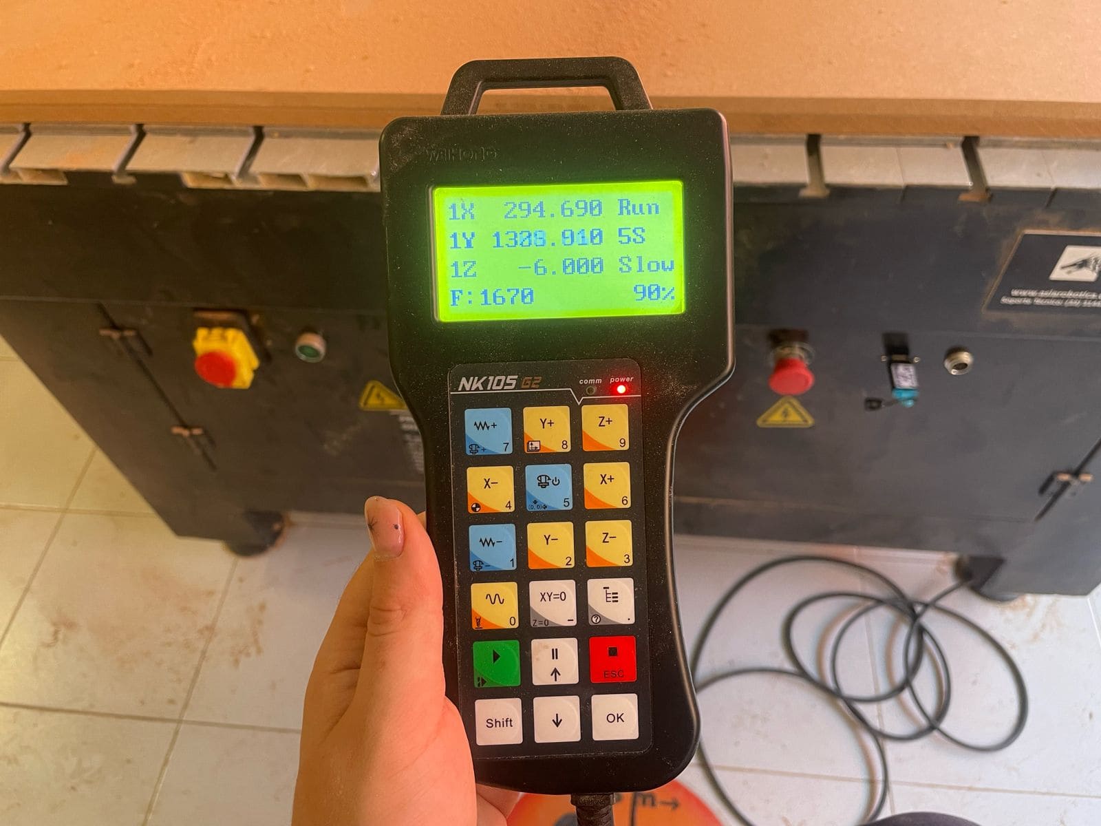
With my file ready, I went over the CNC Machine and inserted my USB drive, I was ready to start, but first I needed to calibrate the machine, in order to cut everything correctly. I used the remote to move the drill to the bottom left corner, where I had placed the 0,0. Then I moved the drill up and down to find the Z axis. Now we are ready! I clicked on my file and the machine started spinning and moving following the VCarve File.
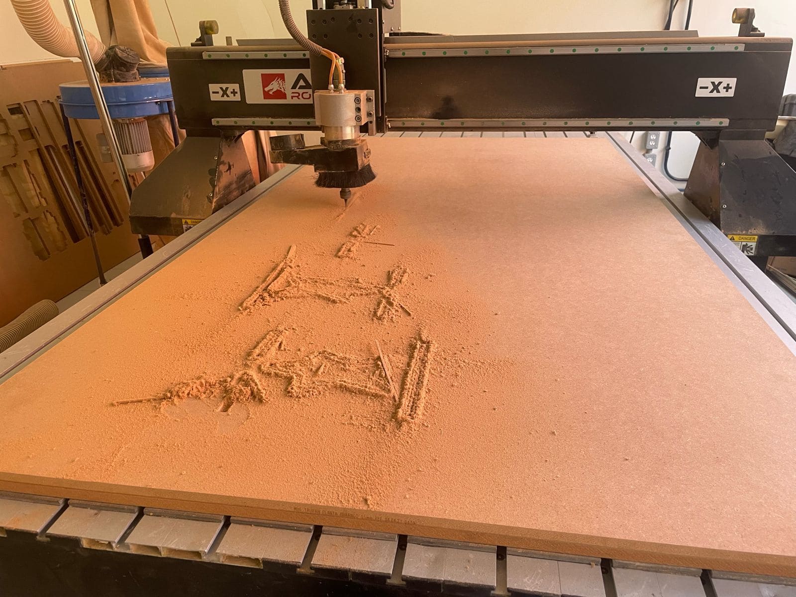
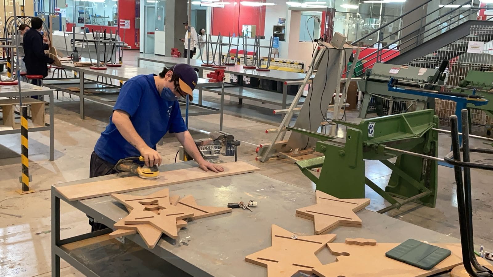
After approximately 20 minutes, my pieces were ready. I took them all out of the panel and cleaned the machine. I just need to sand them and assemble them.
