Week 13 Embedded Networking and Communications
This is the group assignment Website Fab Lab Puebla
- Group assignment:
- Send a message between two projects
- Document your work to the group work page and reflect on your individual page what you learned
- Individual assignment:
- Design, build, and connect wired or wireless node(s) with network or bus addresses and a local interface
For this week's group assignment, we are sending a message between two projects.
UART communication is a communication protocol that permits the exchange of data between two MCUs. It uses at least two communication pins (RX and TX), which means reception and transmission and the reference GND pin. This implies that it operates in full-duplex mode, enabling simultaneous sending and receiving. It can also have a clock signal, making synchronous communication possible. Since we are operating autonomously, the speed and format of our messages will remain consistent. This ensures that there are no issues with misdirected messages.
Overview of UART and I2C Communications
UART (Universal Asynchronous Receiver/Transmitter)
UART is a simple, asynchronous communication protocol that allows two devices to communicate using two lines:
- TX (Transmit): Sends data.
- RX (Receive): Receives data.
Key Features:
- Asynchronous: No clock signal is required.
- Full-duplex communication: TX and RX can operate simultaneously.
- Commonly used in serial communication between microcontrollers and peripherals like sensors, displays, etc.
I2C (Inter-Integrated Circuit)
I2C is a synchronous, multi-master, multi-slave communication protocol that uses two lines:
- SDA (Serial Data Line): Transfers data between devices.
- SCL (Serial Clock Line): Synchronizes the data transfer.
Key Features:
- Synchronous: Uses a clock signal for synchronization.
- Supports multiple masters and slaves on the same bus.
- Efficient for short-distance communication, typically used to interface microcontrollers with sensors, EEPROMs, and displays.
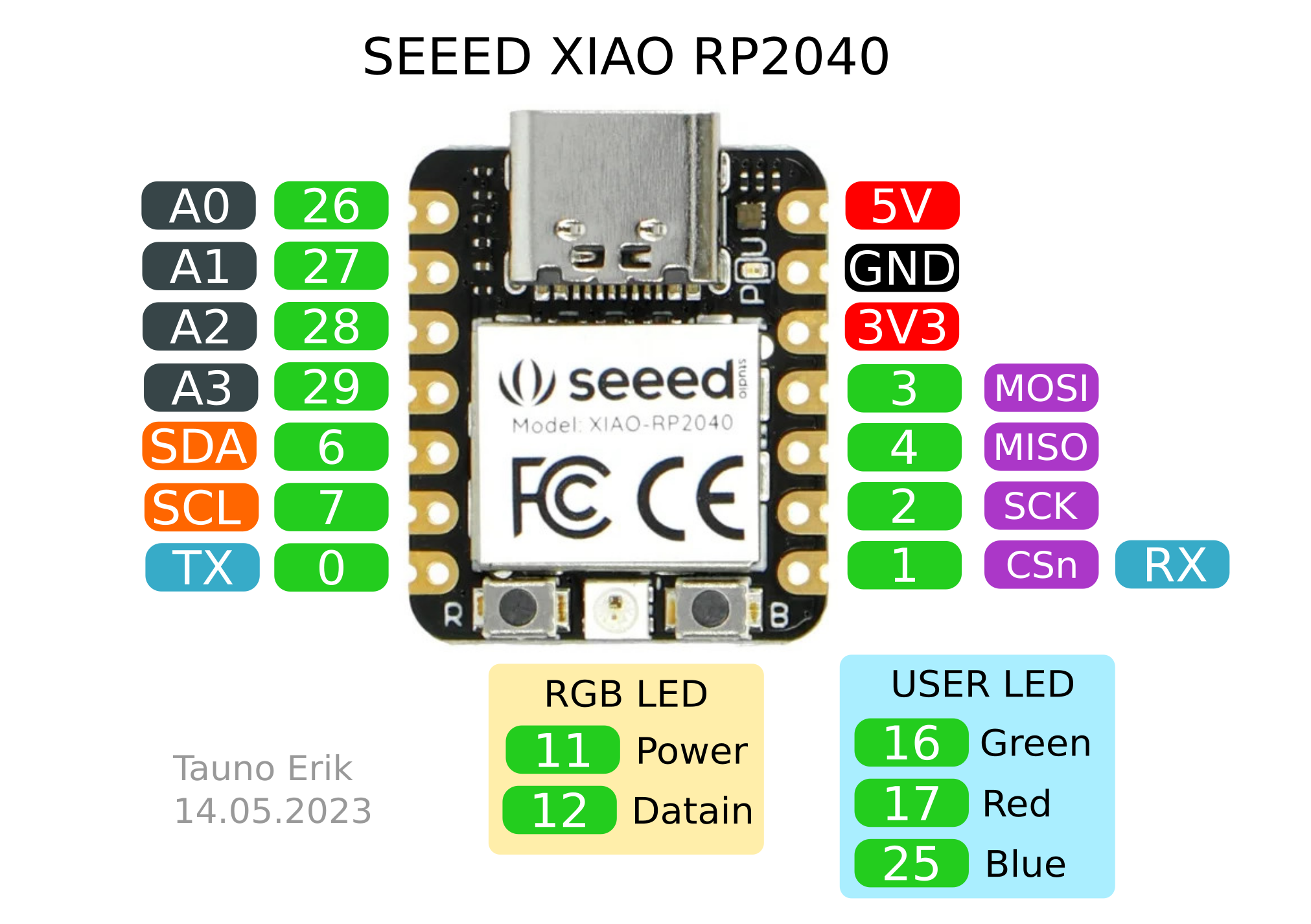
BOARDS PINOUT
this images are very helpful on this week because every 5 min i had to look at them
Also in this week i used 1 arduino, which its a commercial board, and 2 other boards made by me, i designed them and i used on Input and Outputs Weeks take a look if you want to see the schematics week10 and week12
arduino

Xiao

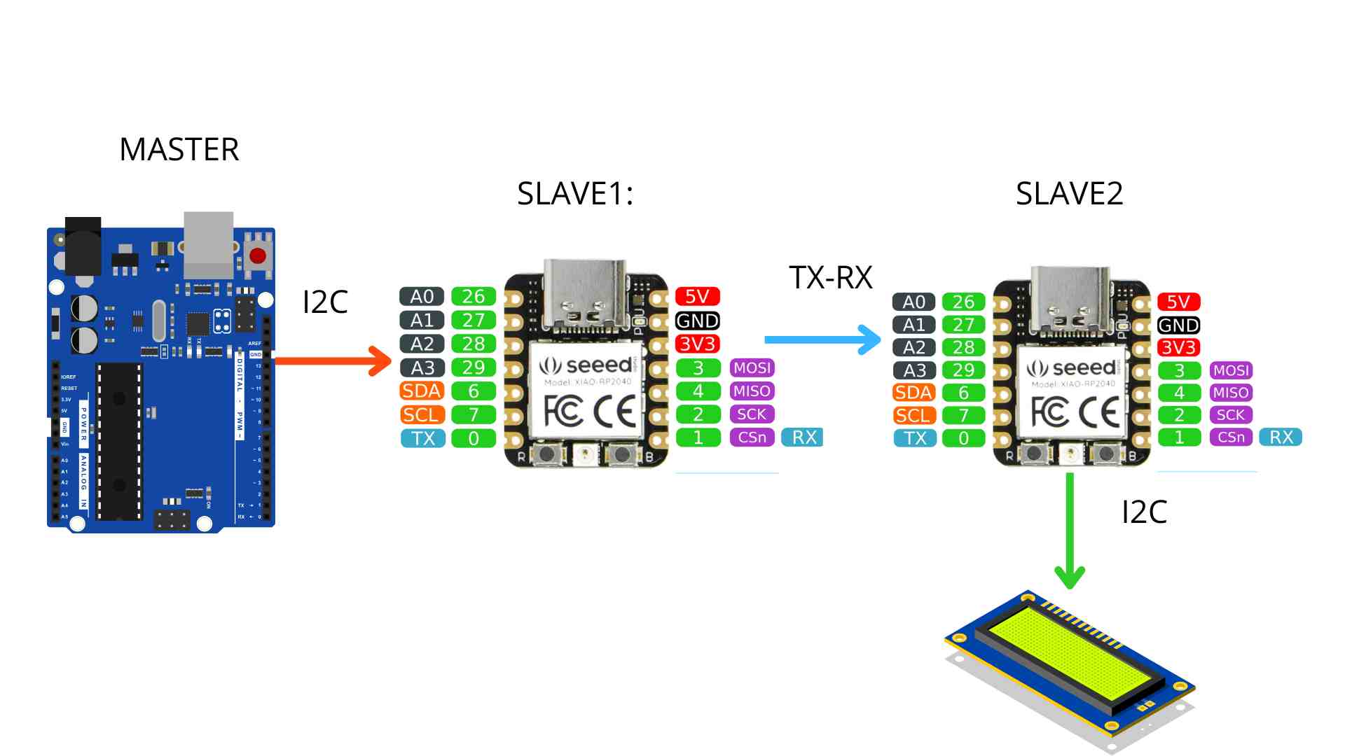
System Functionality Summary

Physical Connections--- HOW TO CONNECT?
1. I2C between Arduino and Slave 1
- Arduino Uno ↔ XIAO RP2040 (Slave 1):
- SDA (A4) ↔ SDA (Pin 4)
- SCL (A5) ↔ SCL (Pin 5)
- GND ↔ GND
2. Serial between Slave 1 and Slave 2
- Slave 1 ↔ Slave 2:
- TX (Pin 6 of Slave 1) ↔ RX (Pin 7 of Slave 2)
- RX (Pin 7 of Slave 1) ↔ TX (Pin 6 of Slave 2)
- GND ↔ GND
3. I2C between Slave 2 and OLED Display
- Slave 2 ↔ OLED Display:
- SDA (Pin 4) ↔ SDA of OLED
- SCL (Pin 5) ↔ SCL of OLED
- GND ↔ GND
- 3.3V ↔ VCC of OLED
HOW IT WORKS?
Arduino Master:
- Sends a value (1, 2, 3) to Slave 1 via I2C.
Slave 1:
- Changes the NeoPixel color based on the received value.
- Sends a descriptive message (RED, GREEN, BLUE) to Slave 2 via Serial1.
Slave 2:
- Displays the message on the OLED screen.
Tests
Verify the NeoPixel on Slave 1:
- It should change color according to the sent value.
Verify the OLED screen on Slave 2:
- It should display the corresponding color text.
What i did? and how?
This week, I conducted research in various repositories and YouTube videos on how to connect Slash House boards via I2C. The code is explained and commented step by step, roughly describing what each line does.
In short, the code works through the Arduino serial monitor, which serves as the master of the, let's say, swarm. You input a value from 1 to 3, corresponding to red, green, or blue, and based on this, the value is sent via I2C to the first board, which is slave number 1.
This value is represented on the NeoPixel: if it's 1, it lights up red; if 2, green; if 3, blue. It then sends the value to an LCD on the second slave. The first slave and the second slave are connected via RXTX, which is a serial communication.
Throughout this week, I faced several issues trying to connect all the boards via I2C. My initial intention was to connect them all through I2C so that, in addition to controlling the NeoPixels, they could also work with the light sensor I use in my PotWix project.
However, I couldn't establish the I2C connections to send data from one slave to the other, likely because the connections conflicted with the LCD on the second slave and the light sensor on the first slave. That was the main drawback: I needed to connect the boards via I2C, but each board was also connected to a sensor via I2C, leading to errors.
I resolved this by using serial communication between the two slaves instead. Below, I will show the Arduino code for the master and both slaves, as well as a video demonstrating how it works, and I’ll attach the supporting documents at the end.
MASTER code
#include   // Biblioteca para comunicación I2C

#define XIAO_ADDR 0x08  // Dirección I2C de la XIAO RP2040

void setup() {
  Wire.begin();  // Iniciar I2C como maestro
  Serial.begin(115200);  // Comunicación con el Monitor Serial
  Serial.println("Arduino UNO listo para enviar datos. ELIGE 1 : ROJO , 2: GREEN, 3 : BLUEEE ");
}

void loop() {
  if (Serial.available()) {
    String tiempoMuestreo = Serial.readStringUntil('\n');  // Leer tiempo de muestreo del Monitor Serial
    int tiempo = tiempoMuestreo.toInt();  // Convertir a número entero

    if (tiempo > 0) {  // Validar que el tiempo sea positivo
      Wire.beginTransmission(XIAO_ADDR);  // Iniciar transmisión I2C con la XIAO
      Wire.write(tiempo);  // Enviar el tiempo de muestreo como entero
      Wire.endTransmission();  // Finalizar transmisión

      Serial.println("COLOR " + String(tiempo) );
    } else {
      Serial.println("Por favor, ingresa un número válido.");
    }

    delay(1000);  // Pausa para evitar envíos continuos
  }
}
Slave 1
#include
#include

#define I2C_ADDRESS 0x08  // Dirección I2C de este esclavo
#define NEOPIXEL_PIN 12   // Pin del NeoPixel integrado
#define ENABLE_PIN 11     // Pin para habilitar la alimentación del NeoPixel
#define NUM_PIXELS 1      // Número de NeoPixels

Adafruit_NeoPixel pixel(NUM_PIXELS, NEOPIXEL_PIN, NEO_GRB + NEO_KHZ800);

void setup() {
  Wire.begin(I2C_ADDRESS);      // Iniciar I2C como esclavo
  Wire.onReceive(receiveEvent); // Evento para recibir datos del maestro

  pinMode(ENABLE_PIN, OUTPUT);
  digitalWrite(ENABLE_PIN, HIGH);  // Activar alimentación al NeoPixel

  pixel.begin();                // Iniciar NeoPixel
  pixel.show();                 // Apagar NeoPixel inicialmente

  Serial1.begin(115200);        // Comunicación serial con Slave 2
}

void loop() {
  // No se requiere lógica adicional aquí
}

void receiveEvent(int howMany) {
  if (Wire.available()) {
    int colorCode = Wire.read();  // Leer datos enviados por el maestro

    // Ajustar color en NeoPixel basado en el código recibido
    switch (colorCode) {
      case 1: pixel.setPixelColor(0, pixel.Color(255, 0, 0)); break; // Rojo
      case 2: pixel.setPixelColor(0, pixel.Color(0, 255, 0)); break; // Verde
      case 3: pixel.setPixelColor(0, pixel.Color(0, 0, 255)); break; // Azul
      default: pixel.setPixelColor(0, 0); break; // Apagar
    }
    pixel.show();  // Actualizar el color del NeoPixel

    // Enviar texto descriptivo a Slave 2 a través de Serial1
    String mensaje;
    switch (colorCode) {
      case 1: mensaje = "RED"; break;
      case 2: mensaje = "GREEN"; break;
      case 3: mensaje = "BLUE"; break;
      default: mensaje = "OFF"; break;
    }

    Serial1.println(mensaje);  // Enviar mensaje al Slave 2
  }
}
Slave 2
#include
#include
#include

#define SCREEN_WIDTH 128  // Ancho del OLED
#define SCREEN_HEIGHT 64  // Alto del OLED
#define OLED_RESET -1     // Pin de reset (no se usa con XIAO)
#define SCREEN_ADDRESS 0x3C  // Dirección I2C de la pantalla OLED
#define I2C_ADDRESS 0x09  // Dirección de esta Slave 2

Adafruit_SSD1306 display(SCREEN_WIDTH, SCREEN_HEIGHT, &Wire, OLED_RESET);

String textoRecibido = "";

void setup() {
  Wire.begin(I2C_ADDRESS);  // Iniciar I2C como esclavo
  Wire.onReceive(receiveEvent);  // Evento para recibir texto desde la Slave 1

  if (!display.begin(SSD1306_SWITCHCAPVCC, SCREEN_ADDRESS)) {
    Serial.println(F("Error al iniciar SSD1306"));
    for (;;);
  }

  display.clearDisplay();
  display.setTextSize(1);
  display.setTextColor(SSD1306_WHITE);
  display.setCursor(0, 0);
  display.println("Esperando datos...");
  display.display();

  Serial.begin(115200);
}

void loop() {
  if (textoRecibido != "") {
    mostrarTextoEnLCD(textoRecibido);
    textoRecibido = "";  // Limpiar después de mostrar
  }
}

void receiveEvent(int howMany) {
  char buffer[32];  // Buffer para recibir el texto
  int index = 0;

  while (Wire.available() && index < sizeof(buffer) - 1) {
    buffer[index++] = Wire.read();
  }
  buffer[index] = '\0';  // Terminar cadena
  textoRecibido = String(buffer);
  Serial.println("Texto recibido: " + textoRecibido);
}

void mostrarTextoEnLCD(String texto) {
  display.clearDisplay();
  display.setCursor(0, 0);
  display.println("Color:");
  display.setCursor(0, 16);
  display.println(texto);
  display.display();
}
Final results


Video
