Week 7 Computer-Controlled Machining
CCM
Computer-Controlled Machining (CCM), more commonly known by its subset, Computer Numerical Control (CNC) machining, refers to the process of using computers to control machine tools for the purpose of manufacturing complex parts and components from various materials. This technology enables the precise and automated control of machines such as lathes, mills, routers, and grinders.
For this week assigment i decided to create a wine rack.
⚠️ Precautions to take ⚠️
Be careful with potential hazards:
- Splinters
- Cuts
- Burns
- Impacts
- Fires
- Tool Breaking
Before cut anything in the router, you must locate where the fire extinguishers are in case of fire.
Don't forget to use :
- Safety Goggles
- Noise Headset (optional)
- Lab Coat
- Safety Boots
- Face Mask
- Tied-up hair
And prepare a training with a supervisor to learn the basis rules to use the router.
I used the Asia robotica router, with the following specifications
| Details | |
|---|---|
| Power | 6Hp at 24,000 RPM's |
| Working area | (X) 1220 x (Y) 2440 x (Z) 200mm |
| Precision | +/- 0.15 mm |
| Maximum speed | 25,000 mm/min |
| Clamping | Clamps (included) / Pneumatic rollers and/or vacuum pump (both optional) |
Features:
- Water-cooled Spindle motor of 6 Hp at 24,000 rpm continues the Shop's great power.
- The favorite model of entrepreneurs. Now with vacuum clamping with a 10 hp turbine-type pump (optional).
- It has 4 suction areas to adapt to your cutting needs.
- Designed to work 24/7.
- Its design and assembly quality is intended to forget about vibrated cuts and/or imperfections in the work.
- Cabinet integrated into the equipment structure, to minimize space.
Emergency Stop
Also its important to know where is the emergency stop i left you this image, of where is locate in my cnc router

Materials
Here are the materials to work.
| Material | Size |
|---|---|
| MDF | 1200 x 2400 mm and 15mm thickness |
| Drill | 6.35 mm diameter |
Assigments
Individual Assignment
make (design+mill+assemble) something big (~meter-scale)
Extra Credit
- Don't use fasteners or glue
- Include curved surfaces
Group Assignment
- Do your lab's safety training
- Test runout, alignment, fixturing, speeds, feeds, materials, and toolpaths for your machine
Group recap
Here i left you our group assigment if you want to see it
- Design & V CarvePro
- Asemblying my wine rack
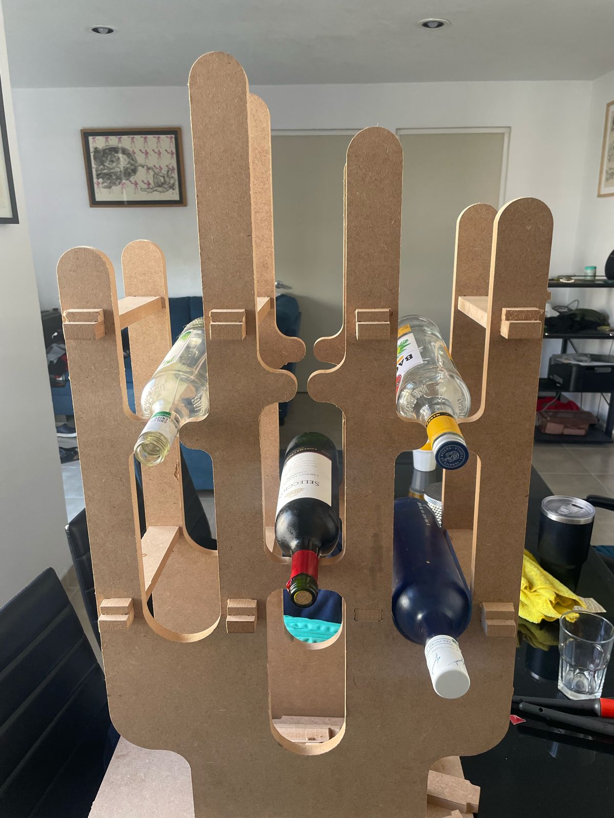
In this activity, i came up with the idea to make a wine rack, which is really for storing my bottles when my friends come over to my house so i can organize them in one place. After making it, i realized that i can also store 1L beer bottles.
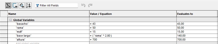
Next, i will briefly describe with images how the four parts that make up this assembly are defined geometrically and dimensionally. To be able to correct the measurements more easily, i added these equations, which are: The size of the MDF, the thickness of the pillars, the length of the base, and the size of the bottles
Designing on solidworks
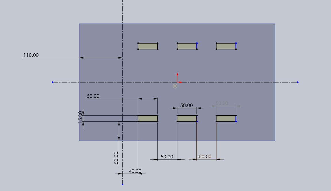
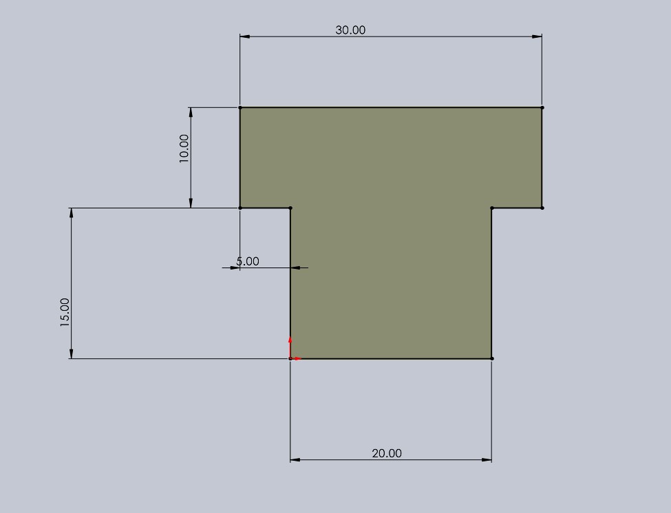
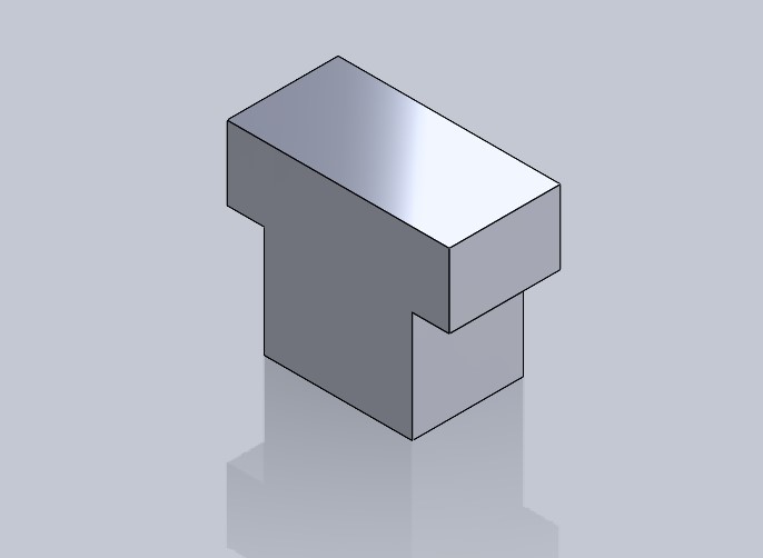
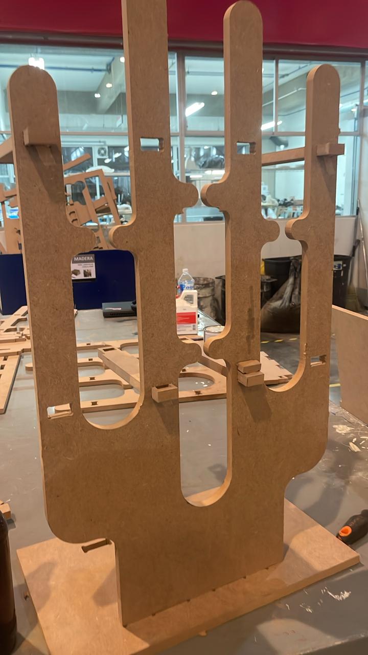
🌵 Piece number 1 🌵
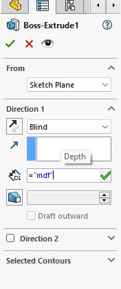
In this piece, I made a sketch in the shape of a cactus where I added most of the equations to keep them related and then gave it a pad with a thickness of 15 mm.
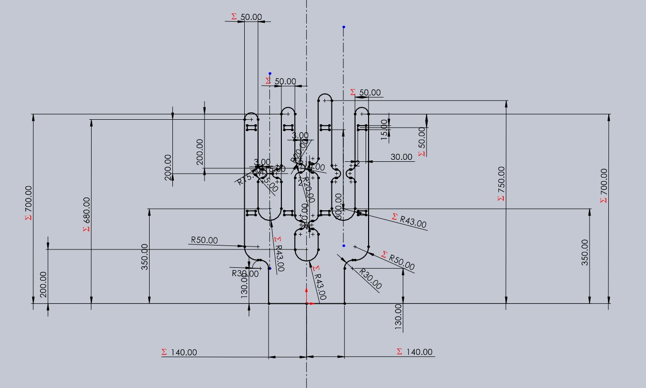
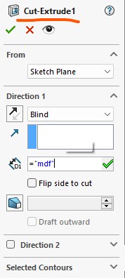
Now I made a cut to create some grooves at the bottom where these will connect with the base of the structure.

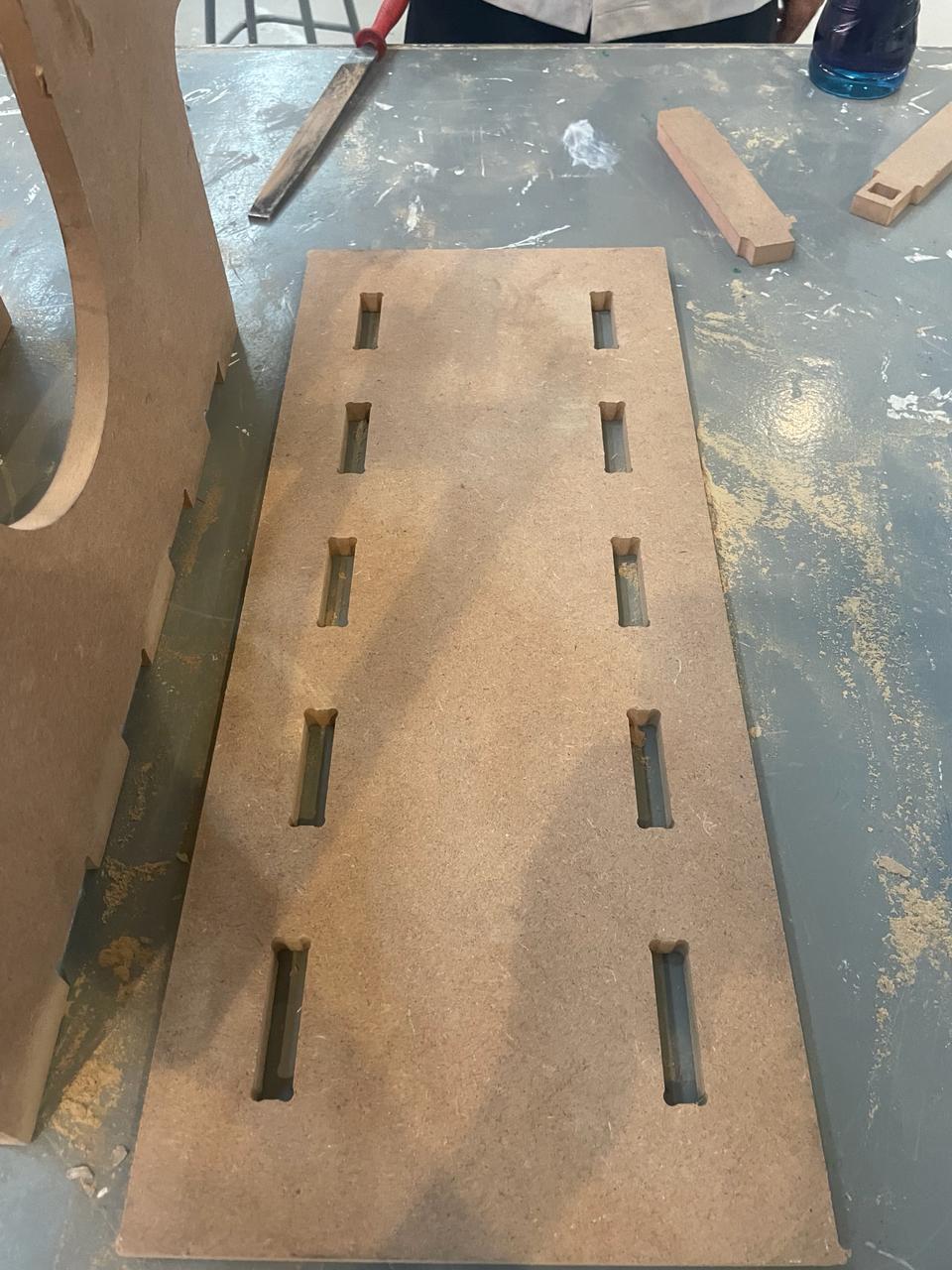
🌵 Piece number 2 🌵
In this piece, I only drew a rectangle that met the width measurement, which should be greater than 200 mm.
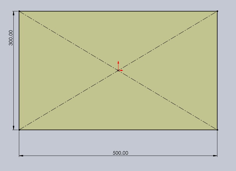
Then, I made the slots where piece 1 would fit.
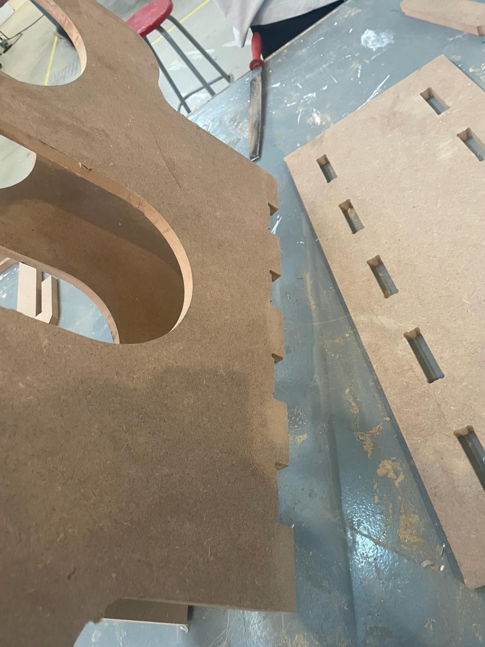
🌵 Piece number 3 🌵
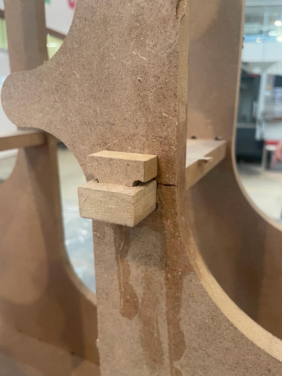
With the third piece, I designed a link to join piece number 1. This link is 30x15x250 mm.
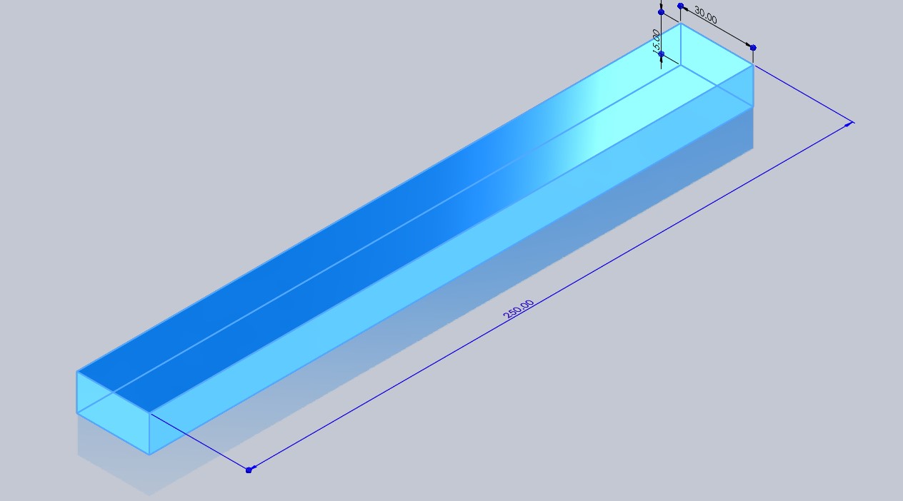
And to prevent movement and them coming out later, I made boxes on both sides for piece number 4 to go into.
Final view :
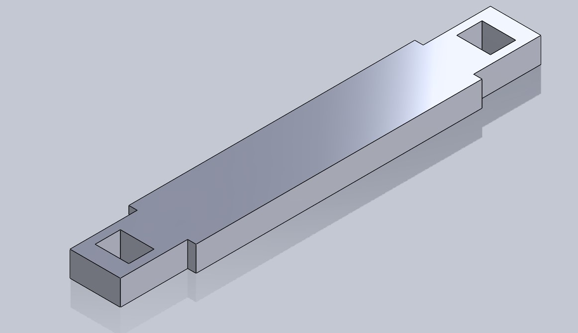
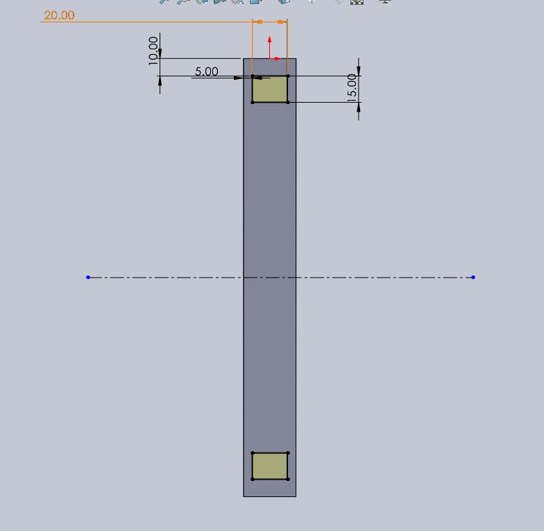
🌵 Piece number 4 🌵
This are the snap fits i designed for the slots on piece number 3.
How to save the document as DXF
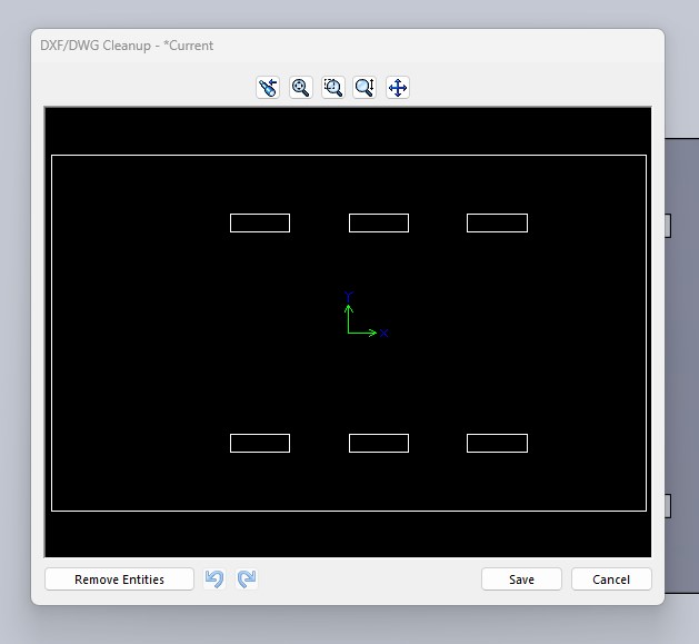
Here i left you these two images, where you only need to CLICK ON SAVE AS > save as type > DXF
Once you clicked on save, the softawre will return you to the part, where you will only need to click on the face which you want to have the dxf file, and it will show you this window.
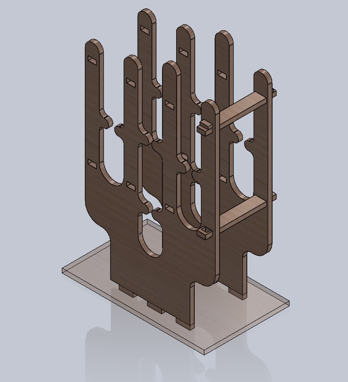
This is how it looks the final assemble, i added a material to look simmilar as the final version. Assemblying all the parts together i could notice it would fit perfectly as i thought.
VCarve Pro
New file
To be able to cut the pieces on the router and import the documents in DXF format, we will need a software called VCarve Pro. The first thing we need to know to add our DXF documents is to create a new worksheet and define the work area. In our case, we were provided with a 15 mm thick MDF sheet that is 120 cm wide and 240 cm long. Also don't forget to set Origin as i did, look at the following image.
Edit objects
This step is very important, before doing anything, we have to join the vectors, so we will have to select all the objects on our worksheet and click on 'close loops', the tool is the one underlined in pink.
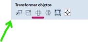
Transform object
In the first image, the one marked with the green arrow, is for moving the desired object , and the one underlined in purple is for rotating it.
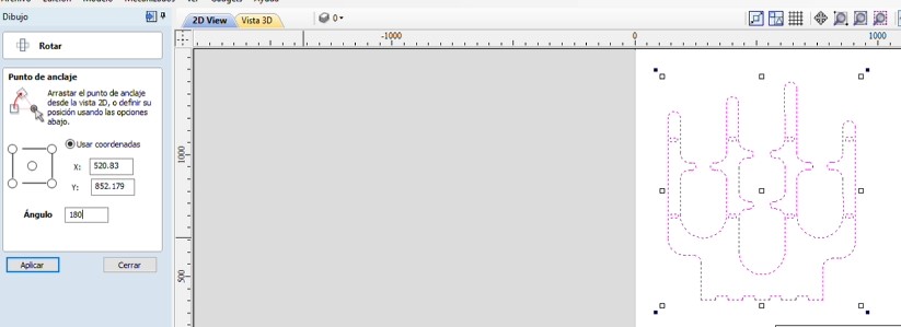
Move
Rotate
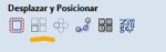
From this image, the one that is underlined is for making arrangements with rows and columns. Good for evitate copy and paste one by one.
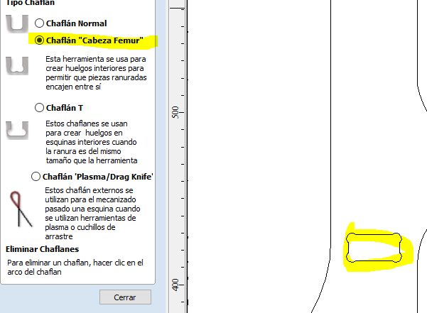
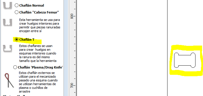
T bones
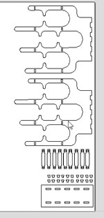
These are all the DXF files arranged for cutting on the router
Simulation parameters
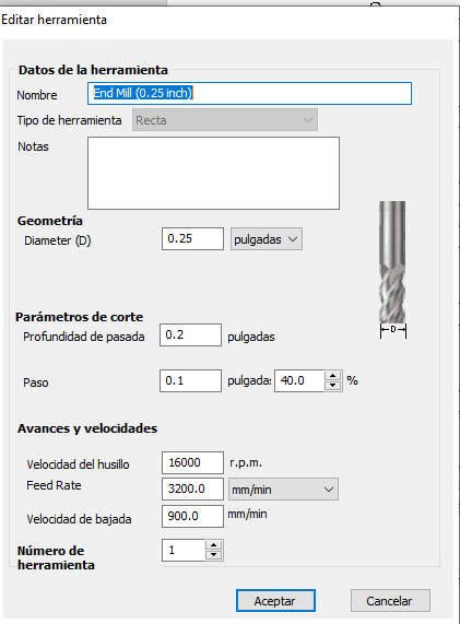
First we must to set up the tool parameters on "Edit tool", do it as the following image.
To perform a correct simulation, first we will need to select the vectors that will be cut from the inside, as this way we will first make the holes, and the pieces will not move. Remember to select the "Inside/Left" option and then click on calculate.
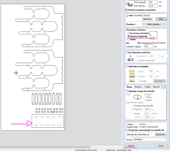
You can see the preview and it must seen as here.
Now we will select the outer vectors, which will define the contour of our object. It's important to change the option to "Outside/Right" in addition to adding tabs to prevent the pieces from flying out when the tool finishes passing. You can add them in "Edit tabs."
Place them where there won't be future connections with other pieces.
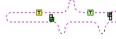
Finally i had to save in these two formats because in our university we have both, so i didn't know in wich one i would work. Make sure to save the two paths.
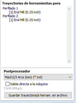
Files
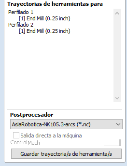
Secure the MDF board
Before starting to cut, the first thing we need to do is ensure that our board doesn't move so that our pieces come out as accurately as possible, by tightening the safety clamps at each of the four corners of the board.
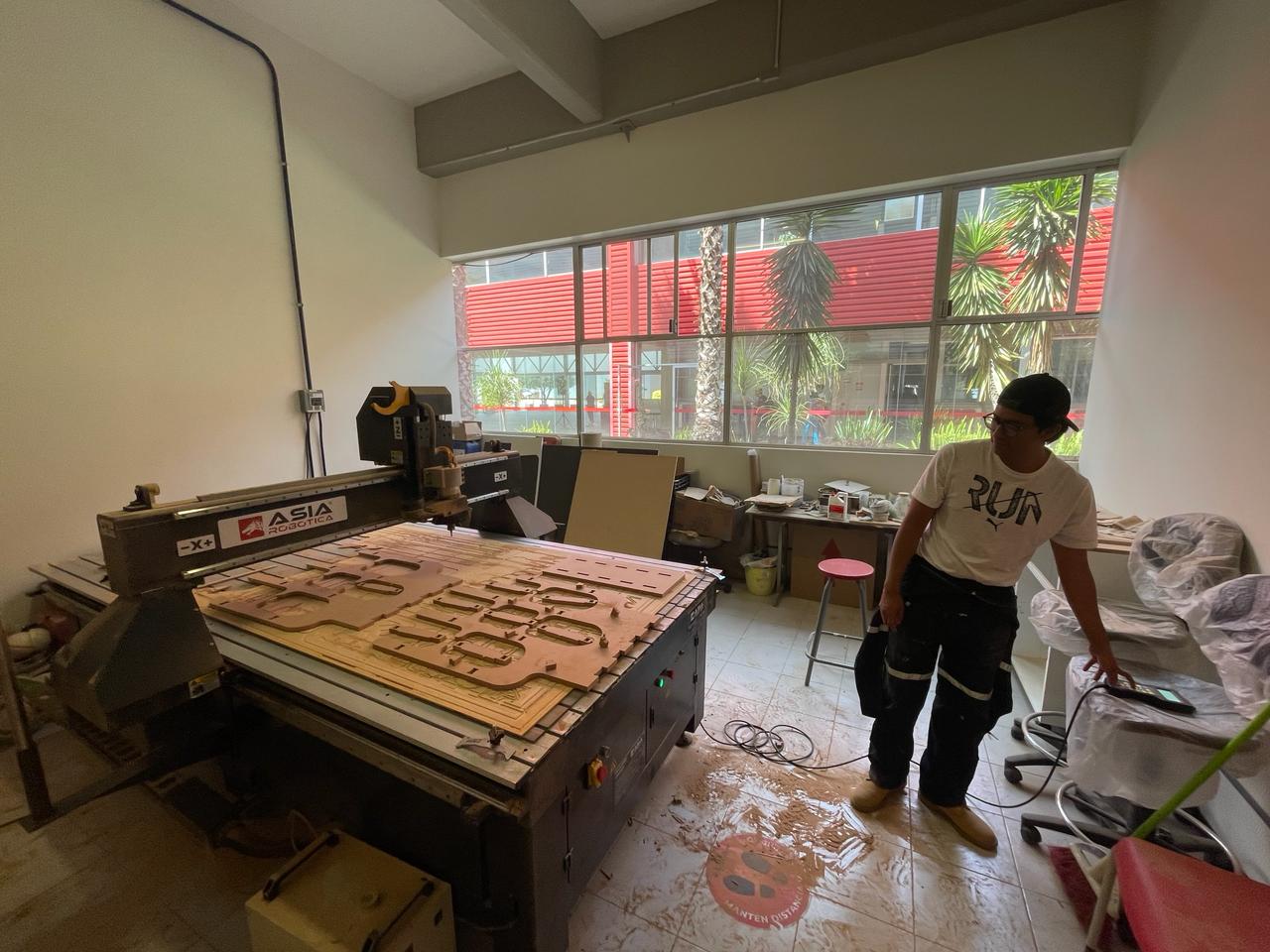
I had the opportunity to work on the AsiaRobotica, which I found very easy to manipulate. With this control, we will add our file and will be able to move in X, Y, Z.
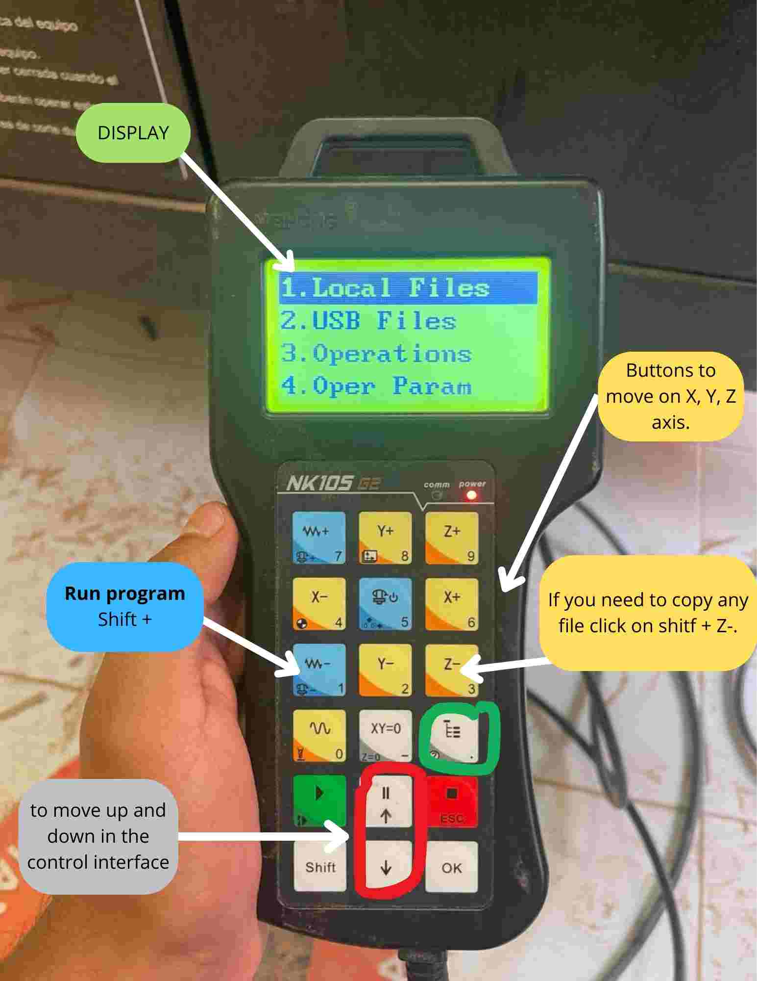
Copy my file
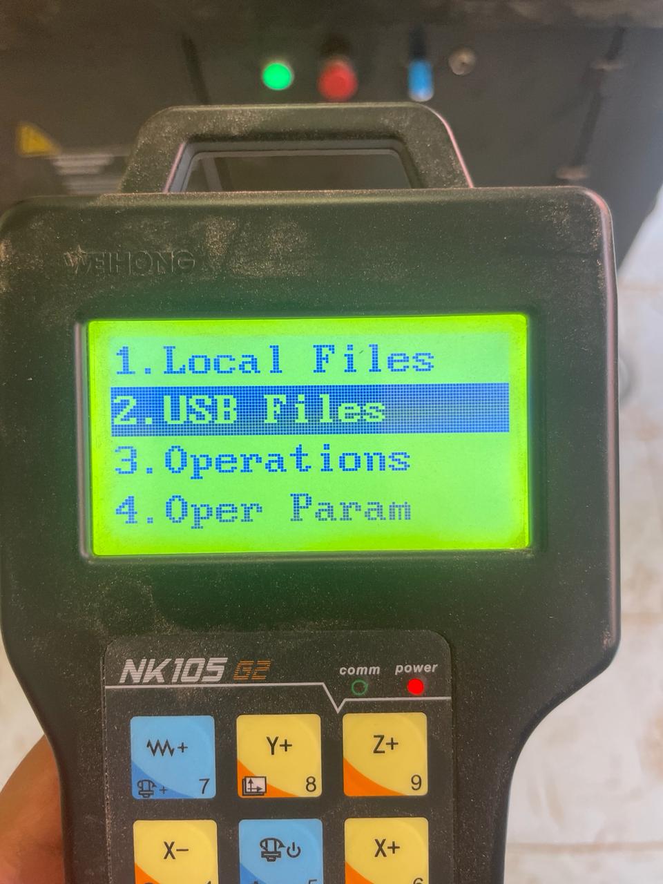
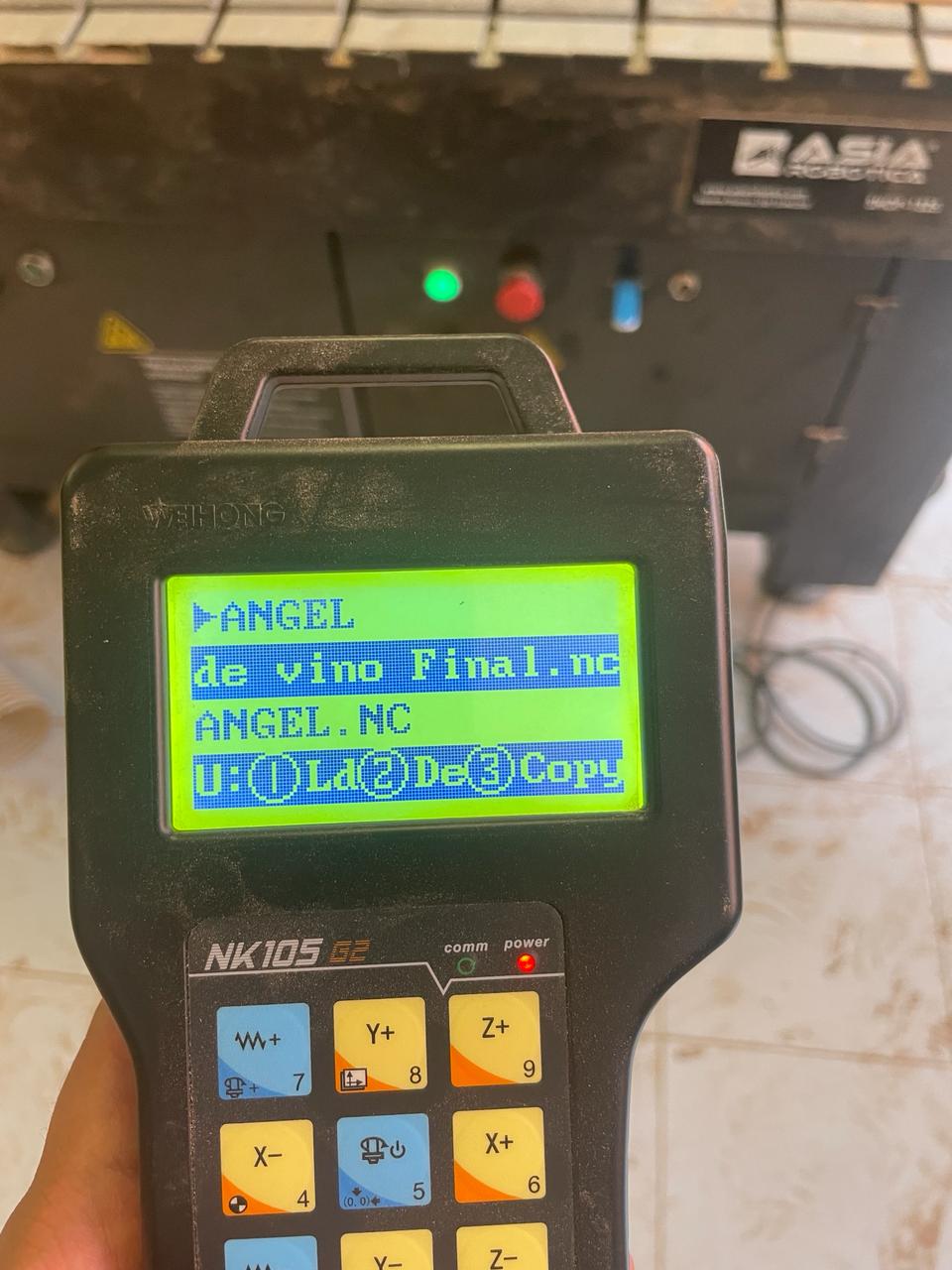
I had my file on my usb, in this machine you can run the program even if the program is in the USB FILES, but if by any reason the usb is disconected the machine will stop the program so my instructor recommend me to copy the file to the local files.
Usb files > *Your file.nc* > Shit + Z- > Esc > Local files > ok
Run the program
Click on your file > Shift + 1 > Run
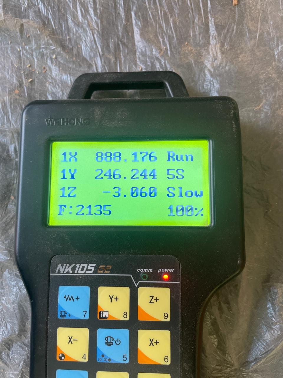
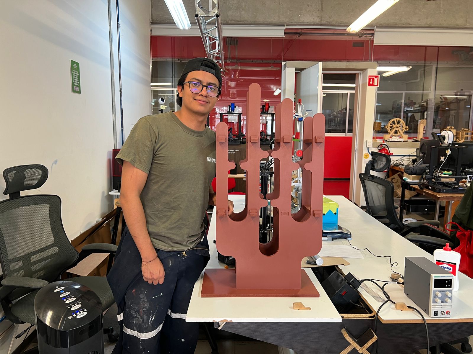
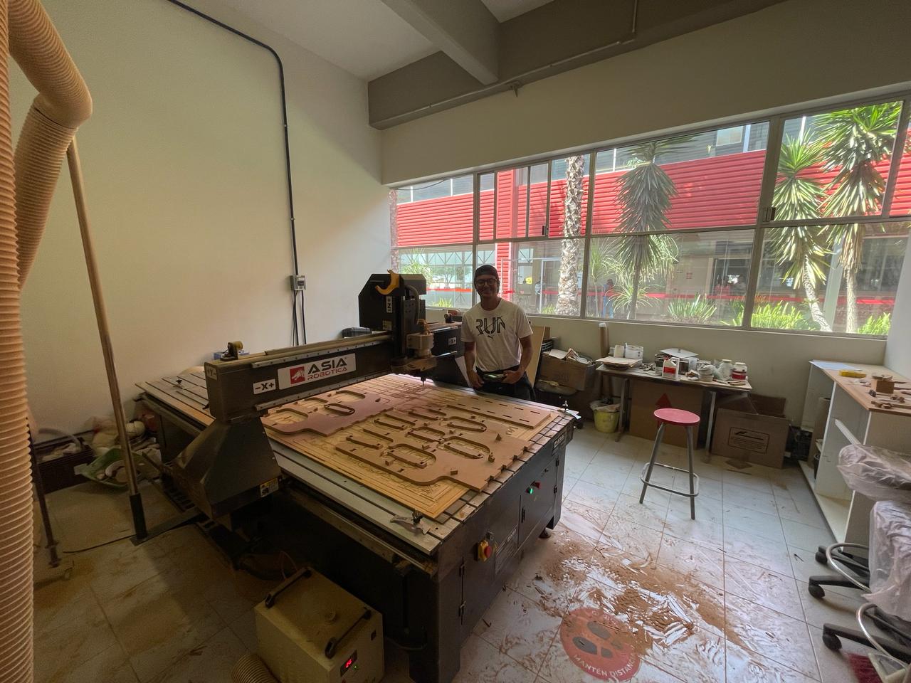
This is me working on the router :)
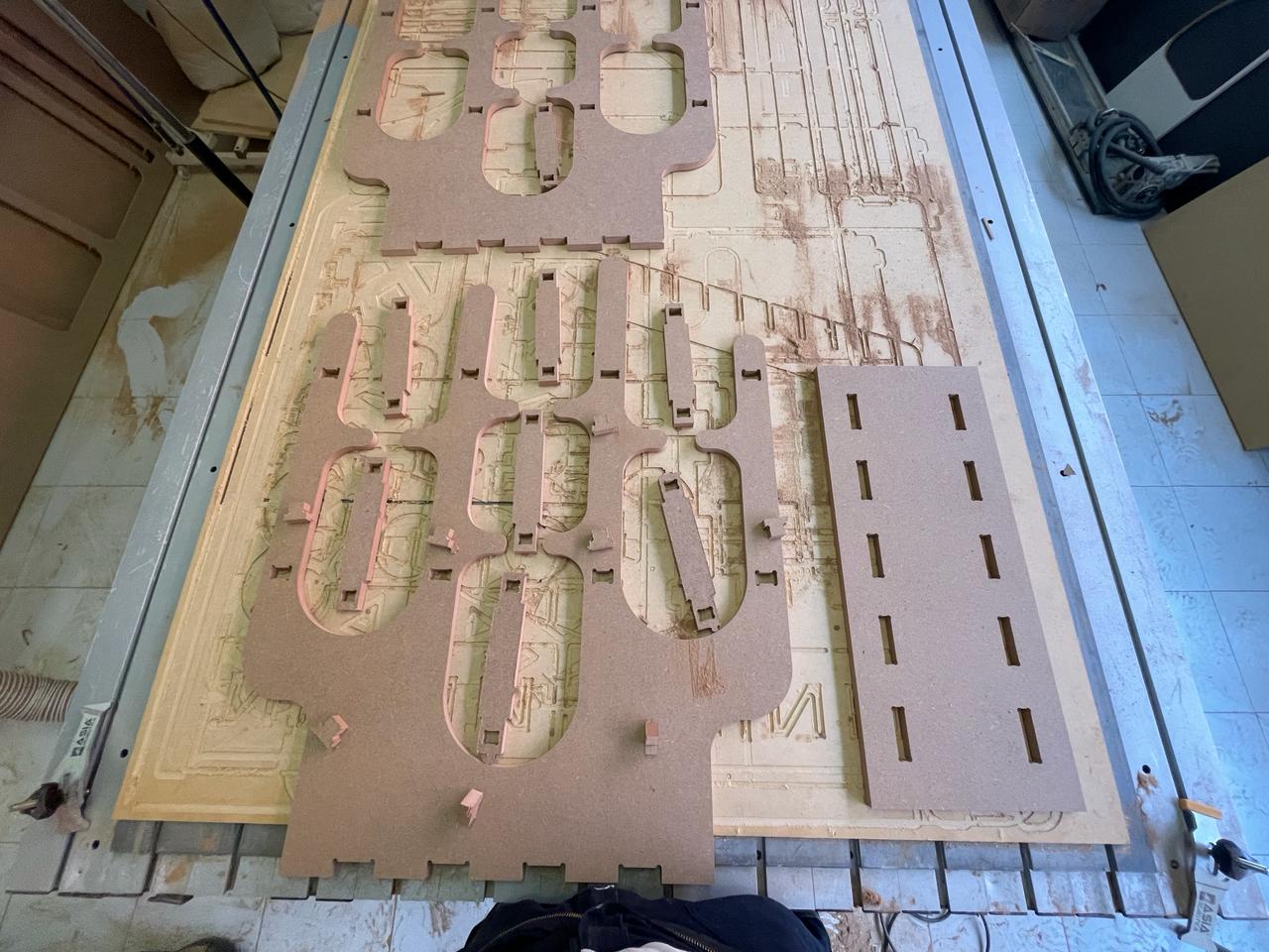
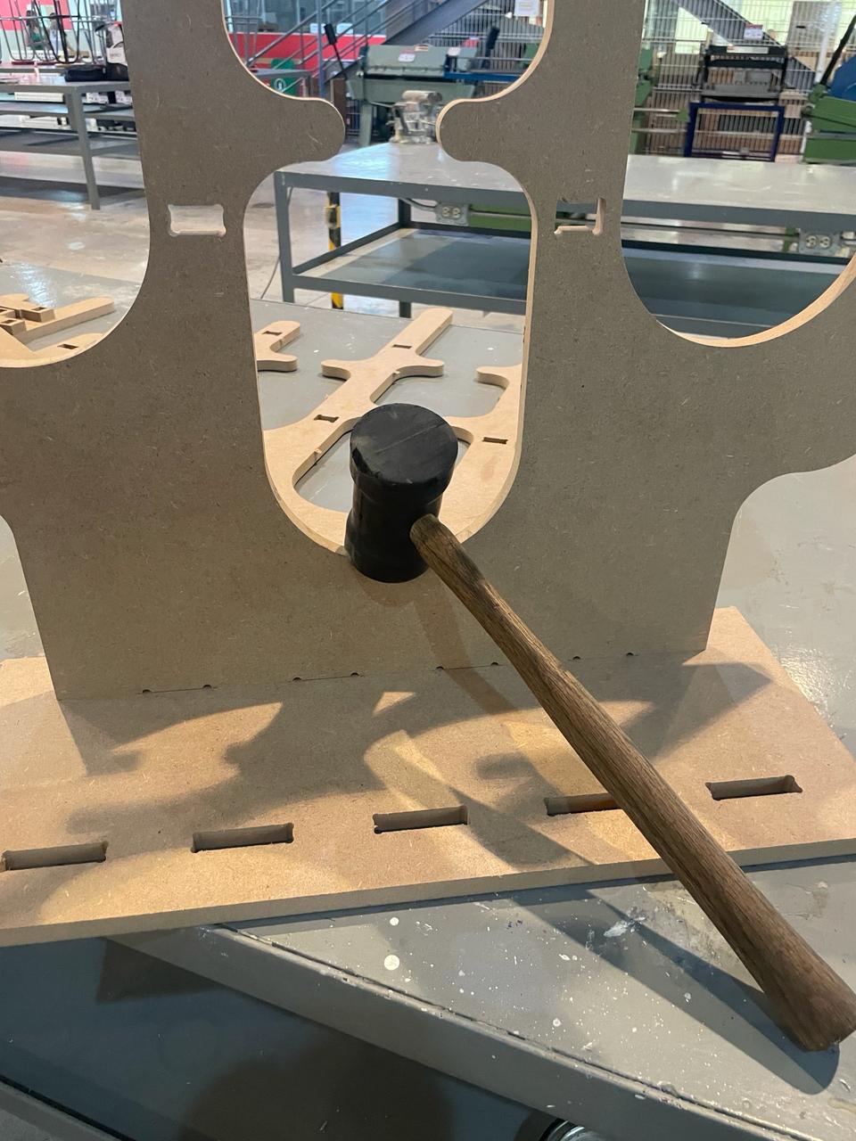
Once the router finishes, you can knock softly your pieces to take it.
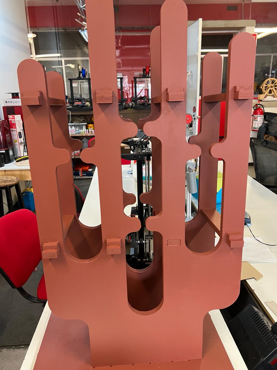
Assembling my wine rack
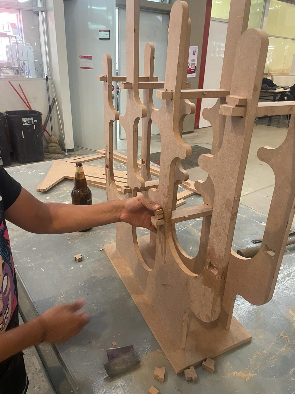
Final product