Computer-controlled machining
The first large format


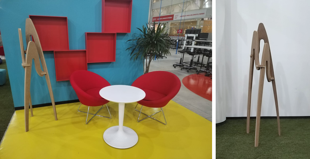
The coat rack
For this exercise, I wanted to work on an object that I needed, so I thought of a coat rack for my office.
I took inspiration from Philippe Starck's "juicy salif"
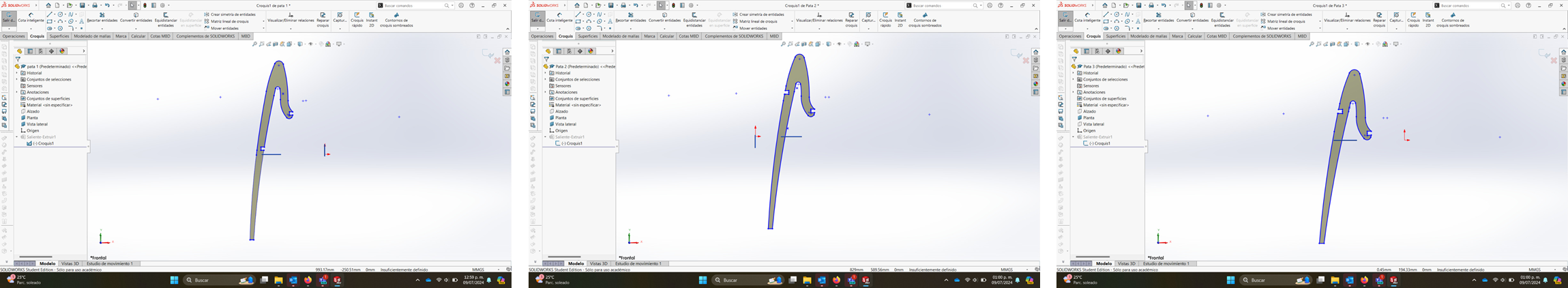
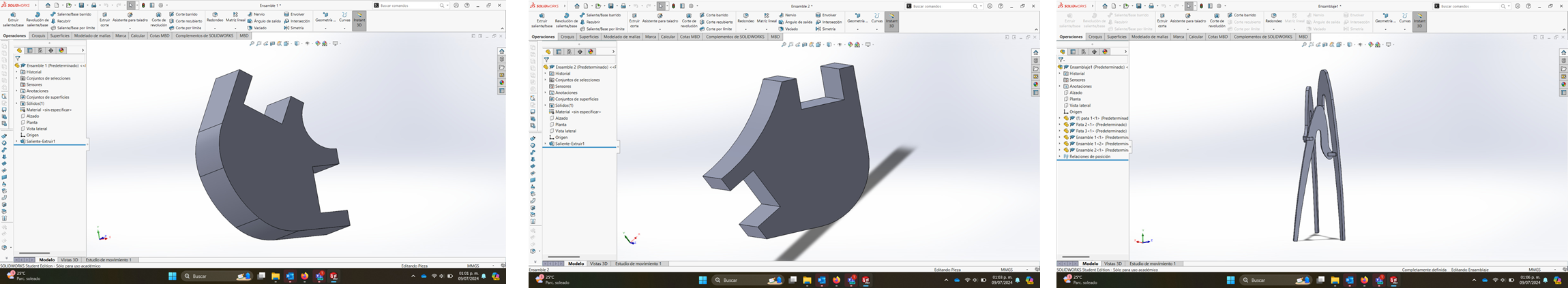
The most challenging part of the design was keeping the inclination of the legs at the angle I wanted without losing the assembly angles, which were key to the stability of the piece.
I used SolidWorks to design the piece.
If you want download the file click Here!
Design process
Pieces were designed separately but, I made a complete plan to download in a single file.
SMART CARVE
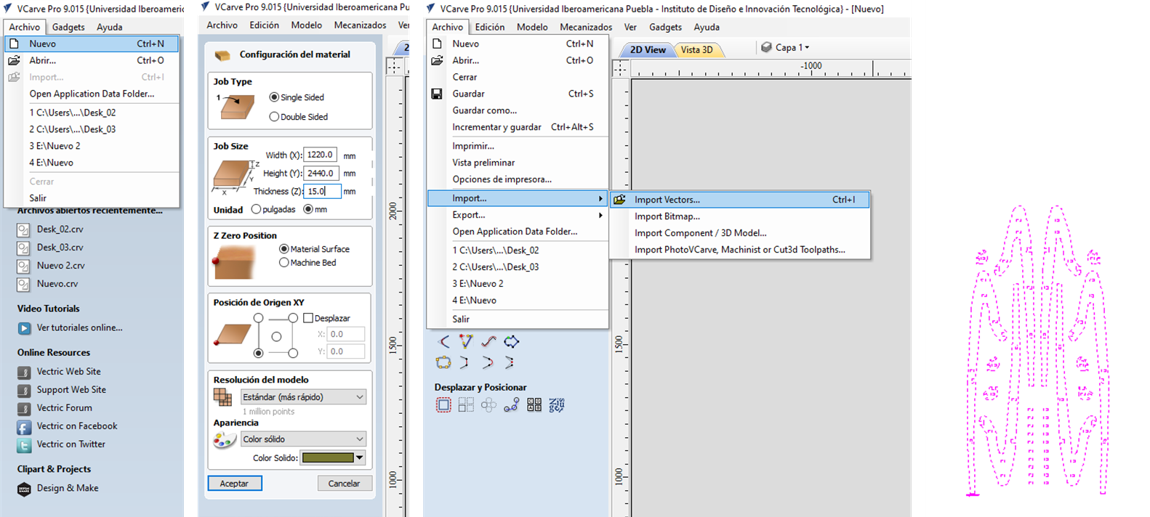
How to prepare the file
V Carve is the software that I used to prepare the file and on this occasion I did not have the need to download it because the university has a license for the software.1- Select the "File" option and create a new one.
2.-The panel with the material configuration appears automatically.
In this case I used a 120 x 240 cm plate with a thickness of 15 mm.
I selected a position for the XY origin and saved the changes.
3.- Import the DXF of the design that I worked on in Solidworks with the Import vectors option.
4.-The model was imported successfully but the size was not indicated.
5.- Once you import the file, the configuration panel changes and shows some tools to edit the drawing.
6.- I selected the "Scale objects" option and changed the percentages to obtain the actual size of the piece.
7.- The piece adapted its size and it was now possible to accommodate it in the work space. (You can double click on the drawing to move it manually)
8.- In this case, select the alignment tool and position the drawing in the center.
9.- I did the arrangement of the pieces from Solidworks. Although in VCarve you can also modify the arrangement of the pieces.
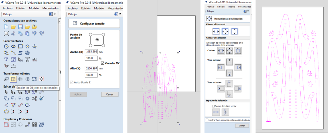
10.-The "Join Vectors" tool is quite useful to ensure that the strokes are closed since, sometimes, software such as Solidworks exports files with open lines.
11.-The "join vectors" tool has the option to modify the tolerances between lines to ensure complete closure.
12.- When the lines are completely closed, you can select the lines and modify their cutting path.
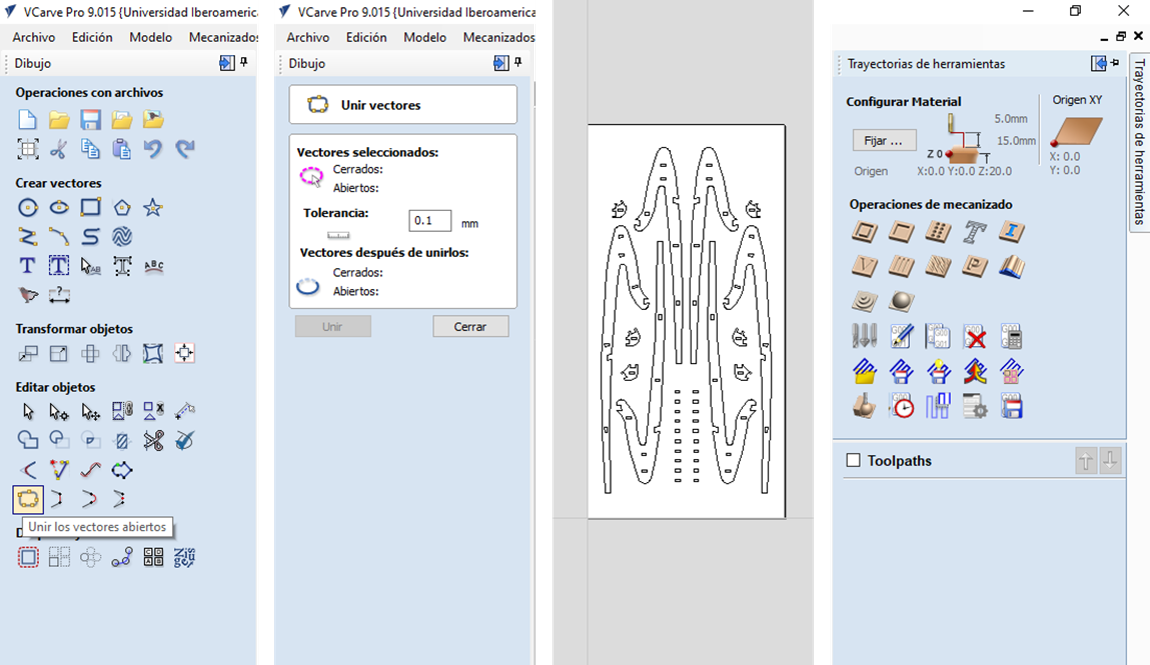
13.- On the right is the "Tool paths" menu where you can select the machining operations for your project.
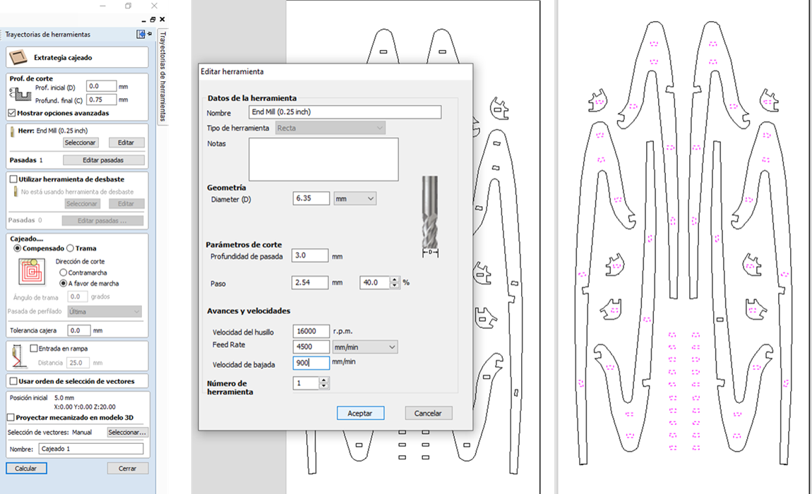
14.- I decided that the coat rack should increase its thickness to have better stability, so I made a mirror of the design
and decided to join it with invisible dowels, which will be cut with the "Box" option, roughing only 7.5 mm inwards.
NOTE: The cutter settings will depend on the type of finish you are looking for, in my case I used a 6.35 mm cutter and set the speed at 16000 RPM
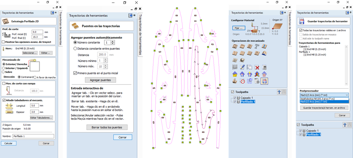
15.- To cut the pieces, select an external cut with a depth slightly greater than the thickness of the material to ensure the cut.
(Always use a sacrificial bed to prevent the cutter from contacting the machine directly)
16.- Bridges are used so that the material does not fall while cutting continues. (It is for safety and stability of the cut)
17.- In the "Tool paths" panel you can view the two cut configurations, so you can save the project.
18.- To save the project it is important that you have downloaded the Drivers of the machine you will use, in this case, I used the Match 2/3 ARCS.
The Journey
virtuality & reality
This is an example of how from VCarve you can visualize the route that the tools will follow, as well as the time it will take to make the cut.Router CNC
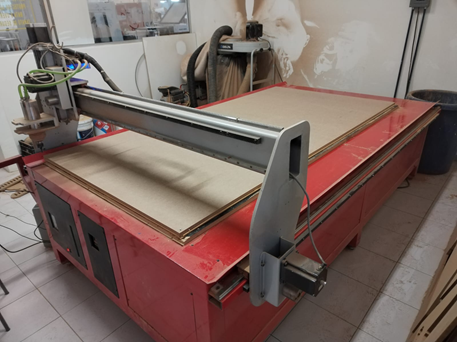
How to use the machine
Remember use safety equipment

 |
 |
| I placed the material on the machine bed and fixed it with nails in the cornersso that it does not move while the cut is being executed. | This machine has a computer next to it so it can be operated, and is positioned in the corner for greater comfort during use. |
 |
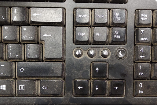 |
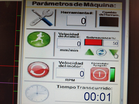
| This is the Panel that allows you to load and configure the cut on the machine as well as the cutting speed and the modification of the origin axes. | With the keyboard you can move the cutter X Left Arrow - Left / Right Arrow - Right Y Up Arrow - Left / Down Arrow - Right Z Re pag - Up / Av pag - Down You can use SHIFT to move faster |
 |
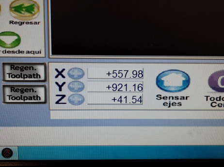 |
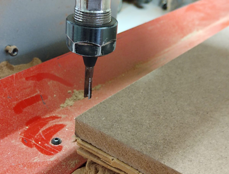
| It is important to position the cutter in the corner of the material to save the origin axes | We save the origin axes of X and Y by clicking on the + sign. And for the Z axis, we position the cutter in the center of the material and go down little by little until we touch the material with the cutter and save by clicking on the + sign |
 |
|
| We start the cut with the Play sign but, we lower the forward speed to 50% so that we can check that the machine is working in order. Once the cutting begins and we verify that everything is in order, we can go up to 100% | Here is the sample of the first trajectory. |
Assembly
This is like a Puzzle
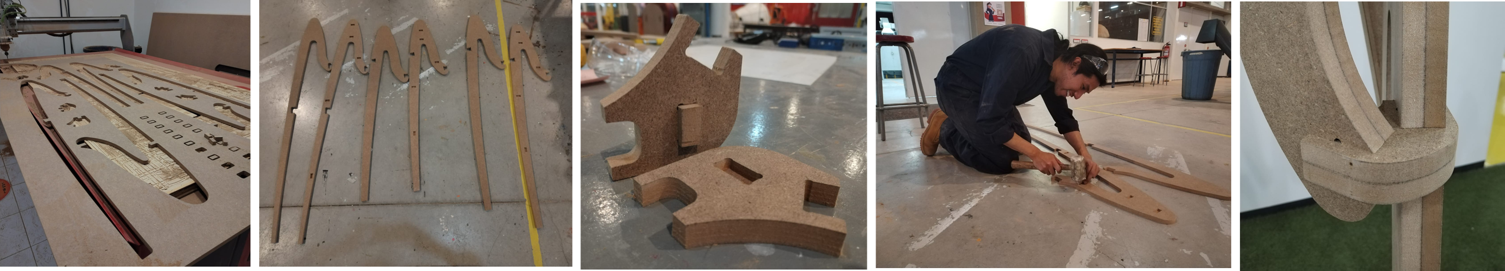
The final result