13. Networks and communications
Week asignments
1. Group assignment: send a message between two projects
2.Individual assignment: design, build, and connect wired or wireless node(s) with network or bus addresses and local input &/or output device(s).
Group asignment
Check out the Puebla FabLab repository: https://fabacademy.org/2024/labs/puebla/week14/
Individual asignment
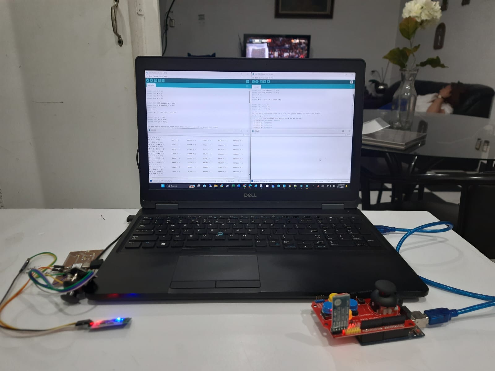
The communication I designed, was between 2 Arduinos, using bluetooth modules and serial protocol. The reason and need for this design, was to explore the communication properties between the radiocontroller and the receiver for my final project
OBJECTIVE
Connect the Xiao + and external HC-05 with an Arduino Uno/Mega + HC-05 and make them communicate.
HOW DOES A BLUETOOTH MODULE WORKS?
Bluetooth modules use radio waves to establish a communication link between devices. They operate in the 2.4 GHz ISM band and employ a technique called frequency hopping spread spectrum (FHSS) to minimize interference from other devices operating in the same frequency range.
Bluetooth networks are called piconets, in a piconet, one device acts as the master while others are slaves. Masters can connect to multiple devices, but slaves can only connect to the master (not to other slaves). By the way, the name is what is typically used to teach the protocol, but I suggest changing Master to Extroverted and Slave to Introverted.
Classic Bluetooth (developed in the late 1990s) operates on 79 channels and is ideal for streaming audio. BLE specializes in low-power applications, such as location tracking and sensor data transmission.
HOW TO CONNECT A BLUETOOTH MODULE TO (ALMOST) ANY BOARD?
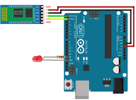
Basically, you will have 4 important pins: RX (communication, receive), TX (communication, transmit), VDD (voltage 3.3 or 5 vcd), GND (ground). Just connect the recommended voltage to VDD, ground it by connecting the common groundings, and connect the bluetooth RX with the board TX, and the Bluetooth TX with the board RX.
WHAT ARE AT COMMANDS?
AT commands are used to communicate with and control modems. They allow users to set parameters, control the modem's operation, and execute specific tasks. One of the most valuable things I learned this week, is that HC05 and HC06 have different AT commands. Therefore, I’ll be using two HC05.
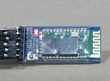
To enter the AT mode or programming mode, push the button un the bottom left part of the module before powering it. After powering it, release the button. If the embedded LED starts flashing, you are done.
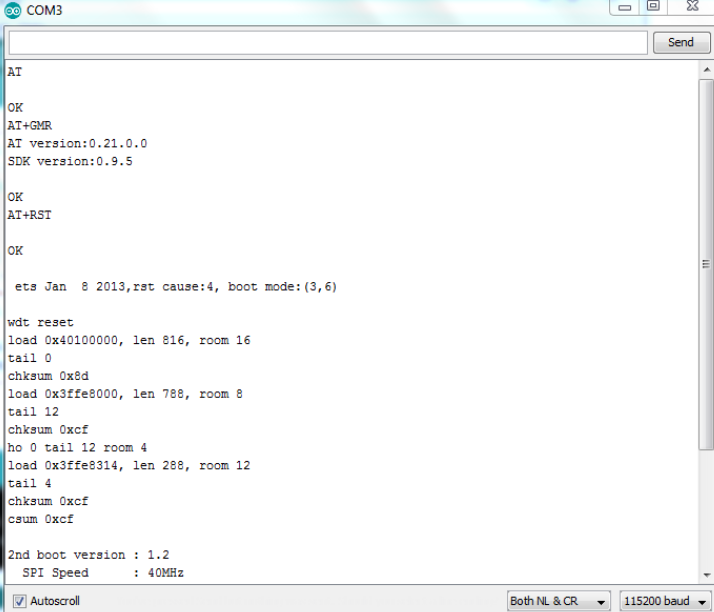
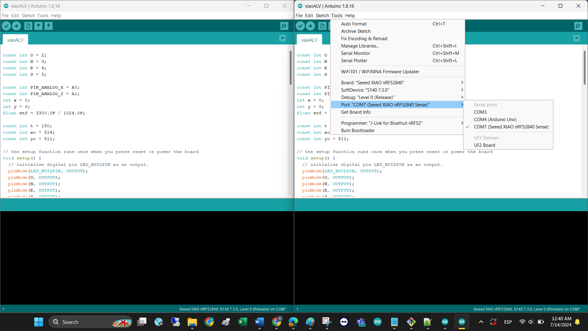
Open Arduino. Go to tools>serial port>select the com port your USB to TTL converter is connected to (to find out, go to device manager of your pc>ports(COM &LPT)) . Now open the serial monitor. The bt module is now communicating at a baud rate of 38400. So change the baud rate to 38400 at bottom right corner of the serial monitor. Also change "no line ending " to "both NL & CR" found just beside the baud rate.
Type "AT" (without the quotes) on the serial monitor and press enter. if "OK" appears then everything is all right and the module is ready to take command. Now you can change the name of the module, retrieve address or version or even reset to factory settings. To see the default name, type AT+NAME. The name will be prompted, by default it is HC-05. To change the name just type AT+NAME=your desired name. Most useful AT commands are:
AT+NAME : See default name
AT+ADDR : see default address
AT+VERSION : See version
AT+UART : See baudrate
AT+ROLE: See role of bt module(1=master/0=slave)
AT+RESET : Reset and exit AT mode
AT+ORGL : Restore factory settings
AT+PSWD: see default password
HOW TO LINK 2 BT MODULES AUTOMATICALLY?
-Determine which Bluetooth is going to be the salve, store its ADDRESS by typing AT+ADDR?. Save the value for the next step.
-Open the Master BT. Type AT+CMODE? to see the connection mode. The default mode is one, which connects to any nearby device. To connect to only one device, type AT+CMODE = Z
-Type AT+BIND = and copy the address of the slave module into the command. Press Enter and type AT+BIND? to confirm the address.
-Turn on and off both systems and verify they connect automatically.
WHAT IS SERIAL COMMUNICATION?
Serial communication establishes a connection between two devices using digital data transmission through a serial port. It involves sending bits of data one after another in a specific order. This allows for the transfer of information between development boards and other devices like computers, sensors, or displays.
Almost all boards have at least one serial port (also known as a UART or USART), they use RX and TX pins to transmit and receive information. In the Arduino IDE, you can use the built-in serial monitor to communicate with the board. Click the serial monitor button in the toolbar and select the same baud rate used in your code’s begin() call.
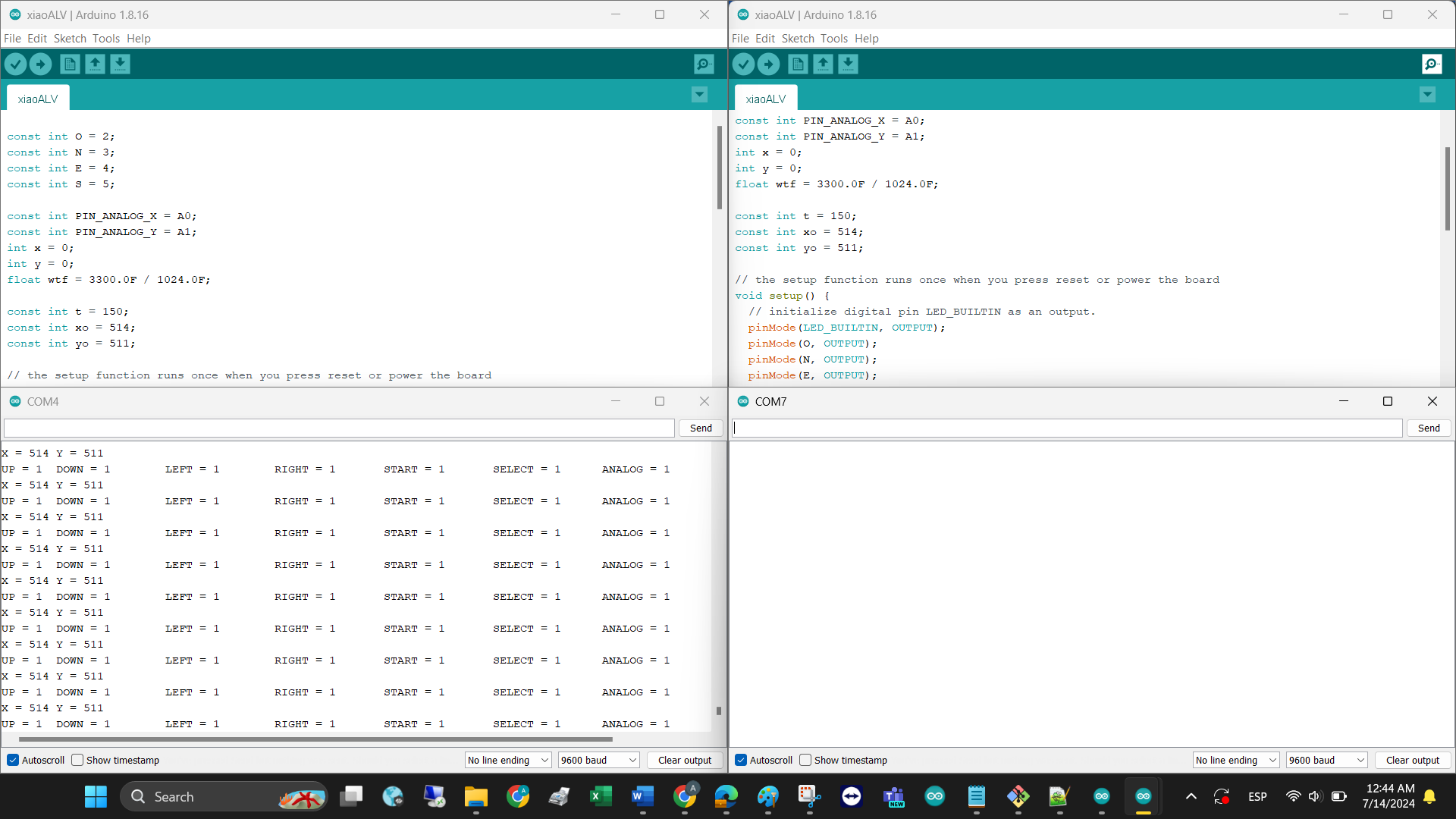
RESULT
Below you can find the code that makes my final project control and car communicate to each other. In the files section, you can find a more simple version of serial communication using bluetooths and arduinos.
SENDER CODE
RECEIVER CODE
