10. Machine Design
Week asignments
1. Design a machine that includes mechanism+actuation+automation+application.
2. Build the mechanical parts and operate it manually.
3. Document the group project and your individual contribution.
Design
We based our design in a 2D cartesian robot that could be inserted into the sewing machine.
Manufacture & manual testing
A 3D printer was used as a test bench, then the mechanisms were repurposed and after many dimesional iterations we achieved nice and smooth displacement of the component. The importance of having a dimensional adjustable design is huge!
Individual contribution
PROJECT SCOPE
Being a nomad FAB student was not complicated until the first group project. If I got behind on documentation or assignments on my own, there was not a huge problem because I’m the only one affected by my actions. However, being in a group is a completely different challenge and I did my best to support the needs of the team and the project. I was contacted by the team leader, and she let me know that we were going to develop a CNC sewing machine similar to this project: https://blog.bricogeek.com/noticias/arduino/maquina-de-coser-automatica-controlada-con-arduino/ I became a member of the WhatsApp group and communication began. Fortunately, I was part of the electronics/software team, which I feel more comfortable with.
INITIAL HARDWARE TEST
Similar projects: Since the base project had no proper documentation for replication, I had to search for similar projects. The pen plotter project that included image divisions by color and pause for changing the pen, perfectly fitted our needs. https://howtomechatronics.com/projects/diy-pen-plotter-with-automatic-tool-changer-cnc-drawing-machine/
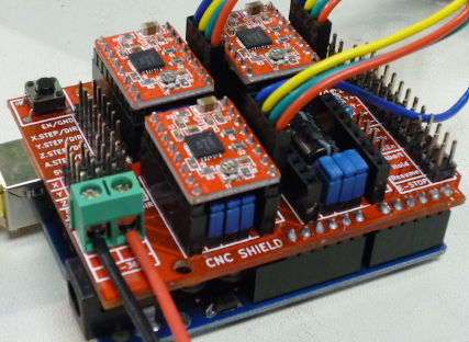
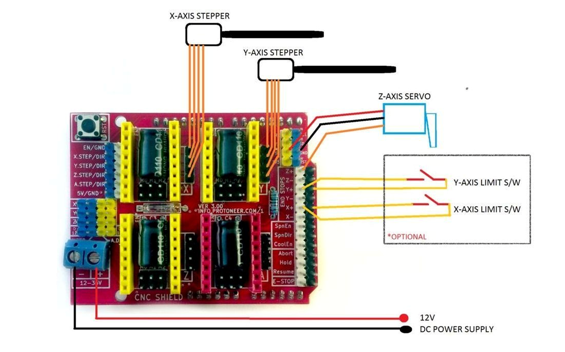
Source the minimum set of materials: I remember from my college final project (hand rehabilitation orthotic), that the components needed for controlling a stepper motor are: 1 stepper motor, 1 stepper motor controller, 1 development board, 1 power source, cables, jumpers. Since I already had the Arduino Uno and the Arduino CNC shield, I decided to dust them off and put them to use.
Connecting everything (Alles ist miteinender verbunden): I had the opportunity to cannibalize an old Ender 3 2d printer and ended up removing the Y motor along with the respective limit switch and dedicated harnesses.
Of course the Arduino IDE should be already installed in our computers and tested with at least the Blink.ino to verify everything works. The GRBL firmware should be downloaded from: https://github.com/gnea/grbl as a ZIP file.
Open the grbl-master.zip file and extract the files, int the Arduino IDE, navigate to Sketch > Include Library > Add .ZIP Library
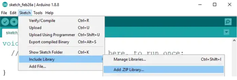
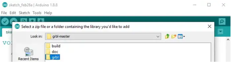
Navigate to the extracted folder “grbl-master”, in there select the “grbl” folder and click the open file. Now we have to load GRBL as an Arduino Library.
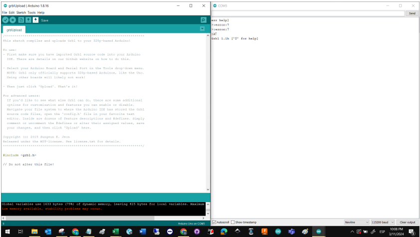
Finally, navigate to File > Examples > grbl > grblUpload. A new sketch will open and we need to upload it to the Arduino board. The code might look weird as it’s just one lines, but not worries, everything happens in the background in the library. So, we just must select the Arduino board, the COM port and hit that upload button and we are done.
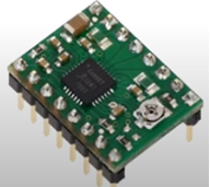
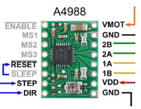
The A4988 controller needs to be adjusted to limit the current flowing inside the motors, a recommended value of 1.5 Amperes will be used as per the Motor data sheet. The mathematical model of the current is: (current limit) = (Vref)x(2.5)
Therefore, the Voltage reference measured between the GND of the circuit and the pot resistor should equal 0.6 VCD.
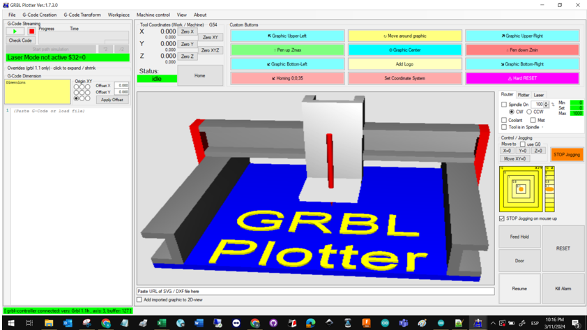
I used the GRBL plotter due to the similarities between the projects. There was a Home button that made the Axis motors work until the limit switches were pressed. This is a video of the first iteration for hardware testing.
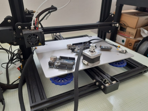
IMPLEMENTING A TEST BENCH
I happened to have a dusty 3D printer (thanks Ramon López for your generous donation) with the same array needed for our project. Therefore, I decided to use it as a test bench while the design team finished our own design. I had to retrofit the terminals (motors and limit switches) to match the Shield pins with materials bought near my Alma Mater.

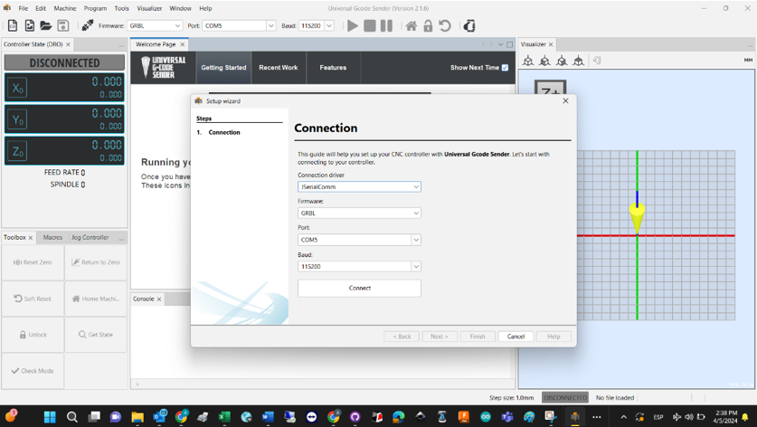
The second A4988 was adjusted, and the new motors characterized. This time, the Vref was set to 0.7 VCD. Finally, the test bench was configured with the UGS wizard feature.
REVERSE ENGINEERING FOR MATERIAL REPURPOSING
An early analysis of the hardware showed that the aluminum profiles were not suitable for the initial design. In the end, it was agreed by all members of the team that the linear motion mechanism from the test bench was going to be repurposed. Initial iterations showed that we should improve our metrology skills, and that the 3 mm MDF was not strong enough to handle the inertia. A chapter on the new design (a beautiful one based on the CNC sewing machine at the IDIT) will be published in the overall project. Special thanks to our sensei Alberto Blanco for giving us the opportunity to take a look at the machine.
The second A4988 was adjusted, and the new motors characterized. This time, the Vref was set to 0.7 VCD. Finally, the test bench was configured with the UGS wizard feature.
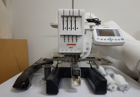
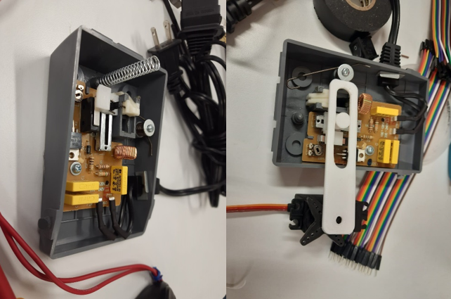
DESIGNING AND IMPLEMENTING A SPEED CONTROL FOR THE SEWING MACHINE.
A challenge that was not considered at the beginning of the project was the speed control for the sewing machine. When we received the authorization for opening the device and inspecting how it works, we figured that a linear potentiometer resistor was the main passive component to be controlled. The fastest solution we came up with, was a simple lever mechanism mounted o a lateral servomotor. The piece was designed, 3d printed, modified, mounted, and tested successfully.