5. 3D(Printing + Scanning)
Week asignments
1. Group assignment: test the design rules for your 3D printer(s).
2. Individual assignment:design and 3D print an object (small, few cm3, limited by printer time) that could not be made subtractively.
3. 3D scan an object (and optionally print it)
3D Printer design rules
Print withing printing volume. Define which kind of material will be printed. Layer height should be maximum 80% of the printing nozzle.
For further information, check out the Puebla FabLab repository: https://fabacademy.org/2024/labs/puebla/week5/
Design and 3DP an object: Simple hinge
After watching an old youtuber I like (Maker’s Muse: https://www.youtube.com/watch?v=7JhjhgjchfM), I gathered information/inspiration about what should I design. In this case, I always wanted to explore how is it possible to print hinges withing 3dprinted models and verifying they work. It still blows my mind. However, it’s not magic but good knowledge in mechanical design and your 3d printers bridging capability
CAD
The creation of a hinge was relatively easy. We can simplify the mechanism by assuming 2 links and 1 pin. The objective of the design is to take advantage of 3DP AKA adding manifacturing and create something that can only be manufactured this way. The perfect example is this because the mechanical constraints will be set since the model itself. Of course, the link 1 should contain or support the pin, and the pin diameter should be smaller than the diameter of the hole from the second link. If the precious conditions are followed, the mechanism will be able to rotate. If the design constraints are not followed, the mechanism will remain solid. Next time I will consider recording the complete design process in SolidWorks, but you can download the model at the bottom of the document. If you have any doubts about CAD, please check the 2nd week from my repository. BTW, never forget to export your finished model to the STL format. It will be necessary for the next step.

SLICING
What kind of verb is that? It is slang for preparing a 3D model to be converted into a printable file. Since we're talking in the context of additive manufacture, 3D model or solid will be conformed layer by layer or slice by slice. This is done via a "Slicer" or dedicated software. From the wide range of varieties, my favorite is Cura. You can download said software from the Makerbot page, and after installing it's important to consider the slicing worflow:
0. If you are using CURA for the first time, you have to declare what kind of 3D printer are you using. In my case, I will use Anselmo Vargas Ender CR-10 (Thanks for lending me that machine for so many years!) After importing the printer model, the layout will be defined, among other parameters
1. Import the STL or OBJ
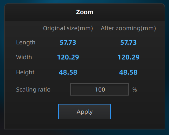
2. Verify it fits inside the printing area. Scaling the object is always an option (depending on the application)
3. Consider the orientation of your model: some configurations save time and material
4. Verify the default settings: you should explore how your printer behaves with the standar profile and values. If you want to understand how this affects, go to the next step
5. Explore new settings: Layer height defines the quality of your print. Line width is determined by the nozzle diamter: remember that the layer height may be as small as 0.15mm with FDM technology, and as big as 85% of the nozzle diameter. The infill determines the ammount of material inside your model. The infill pattern plays an important role in the strength and printing time of your piece. The material section contains the printing temperature which you can set by the filament manufacturar (PLA=185°C) and the plate temperature is only used for other materials sensitive to warping. Speed settings: use slow speeds for initial and final layers (9 mm/s), and 40 mm/s everywhere else. It's slow, but the quality is worth it. Set the cooling value to 100%. Explore the adhesion types! Skirt is my favorite.
6. Slice the model and preview it. Drag the slice bar to check if the areas where your model needs support are properly executed.
7. Save the generated G-Code into an SD card and extract it properly

3D PRINTING
1. Verify the material is loaded, the printing bed leveled and clean.
2. Insert the SD card with the G-Code into the machine and click on print.
3. Verify that the first layers are properly sticking to the surface. Otherwise you need to calibrate the bed.
4. Be patient! This is a slow process, go for a walk or seize the oportunity to document.
5. If everything went well, you can use a spatula to remuve the model. Just be careful. SAFETY FIRST!
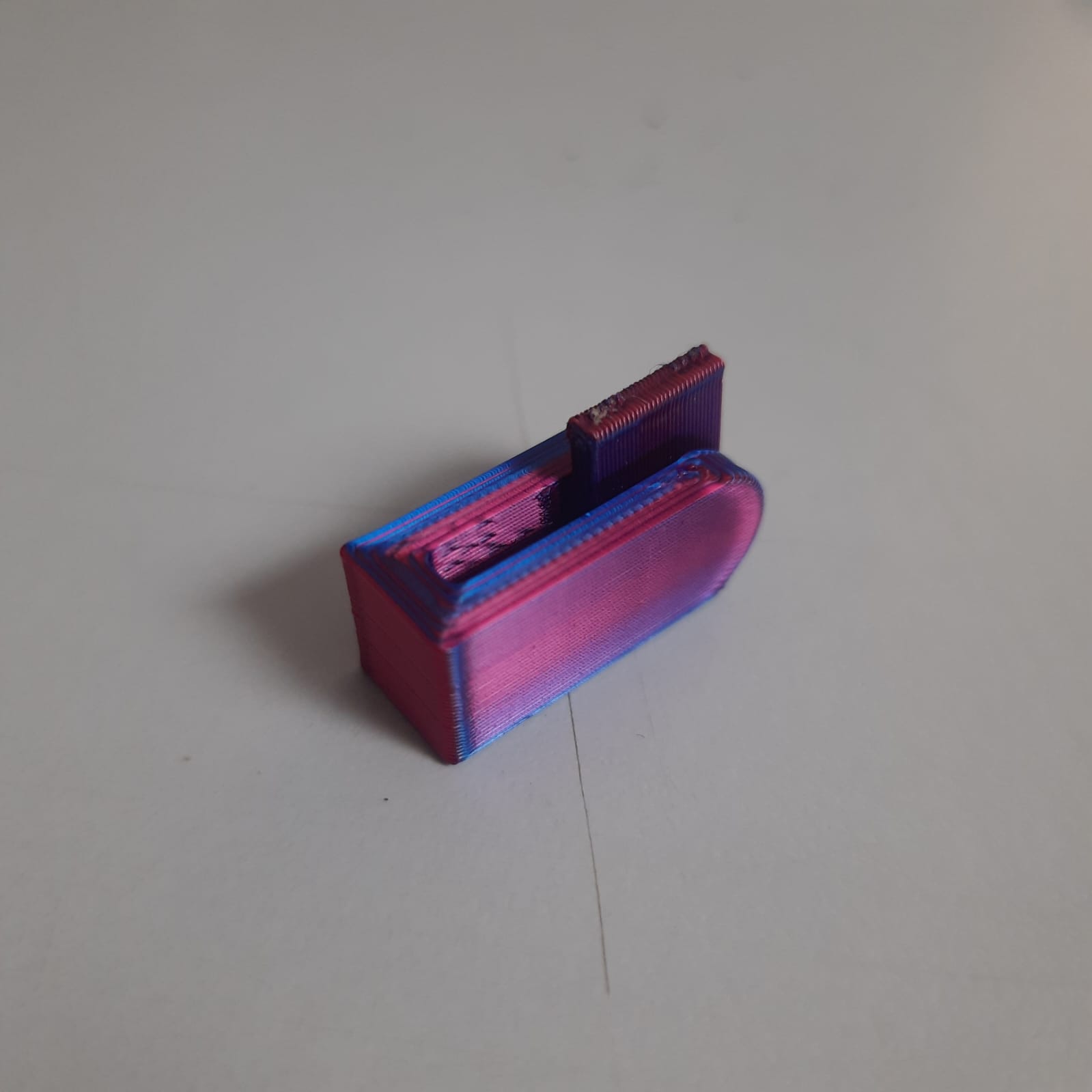
ROOM FOR IMPROVEMENT
Since this was a small piece, the ridges are more notorious. Decreasing the speed and making it bigger will improve the aesthetic finish
3D Scanning
There are multiple ways of scanning an object. The overall recommendations are doing so in a light stable enviroment, doing it over mate finishes or making them mate with dust, and try scanning objects that fit inside rotatory beds; if they dont fit, use handheld scanners or photogrametry
The lab has the Einscan by Shining 3D. The software it uses is called EXScan S> v3.1.3.0 and you can download it for free in the manufacturers page. Of course you have to install it.
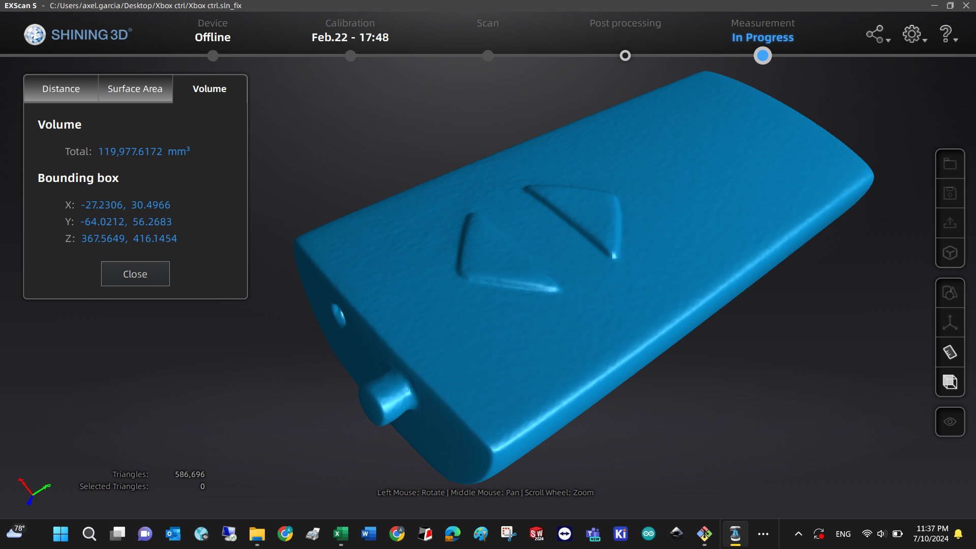
The interface has 5 basic steps which are: Device (verify its connected), Calibration (if you are using it for the first time, you have to follow the instructions in the scanners box), Scan (use it to digitalize an object), Post processing (digital tools for improving the scan), Measurement (distance, area, volume)
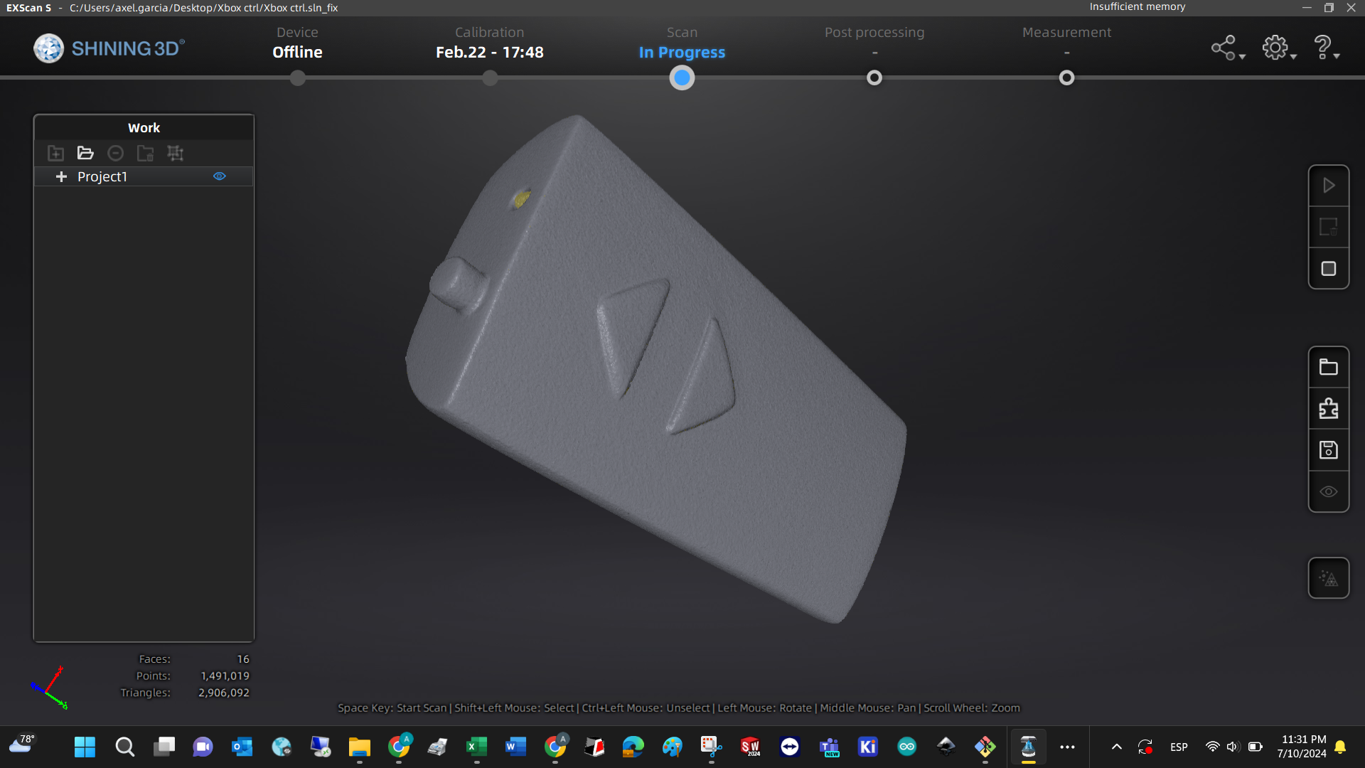
Device: once the software is installed, connect the scanner via USB and to a power outlet. Then turn it on and the software should recognize it as online
Calibration: Dimensional and illumination, each type has its own fixtures or procedures that are contained in the users manual. It takes around 10 minutes to perform them and only if there are considerables changes in illumination or position they should be executed again.
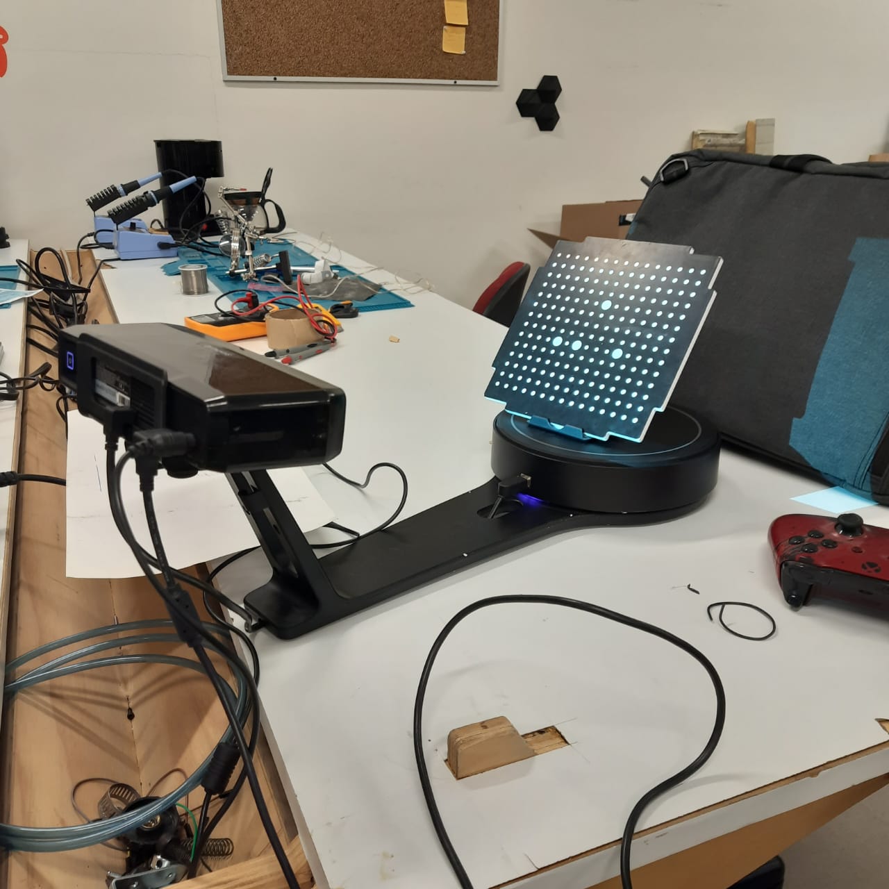
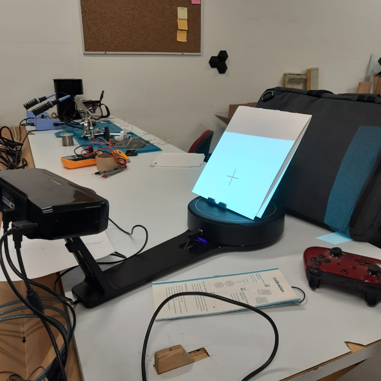
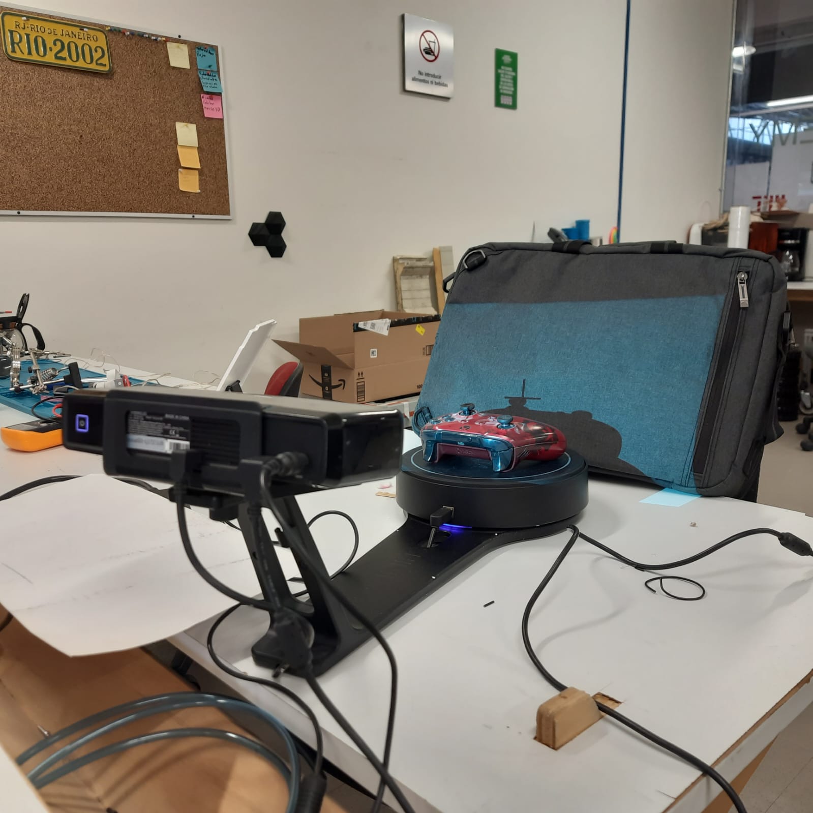
Scan: once your mate-surfaced object is placed in the rotating platform, the scanner will execute the line scaling process and rotation. Eventually the software will ask you to reposition the piece to have a decent ammount of information for closing the mesh.
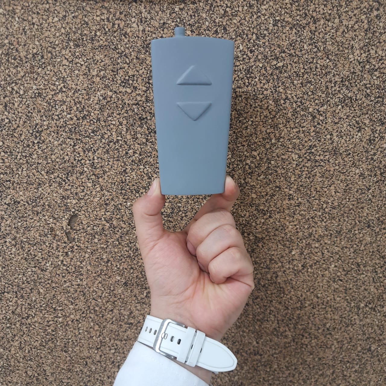
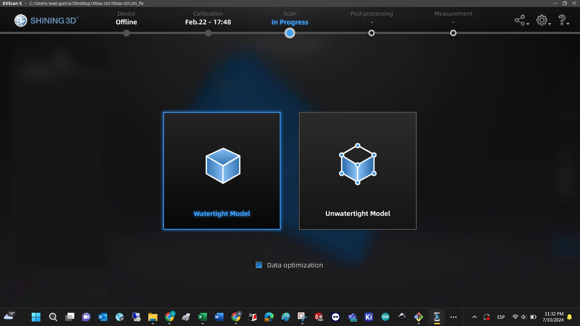
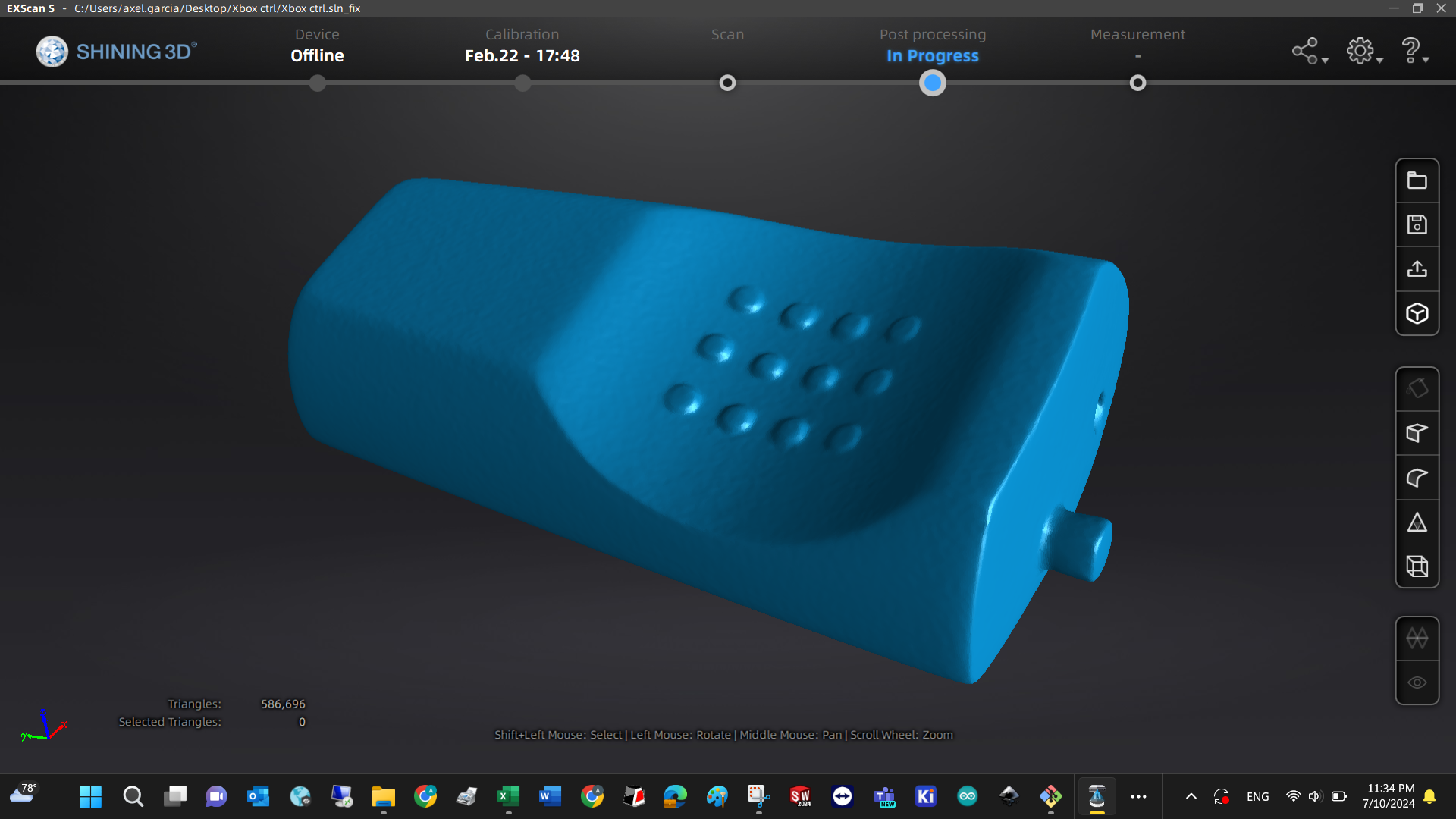
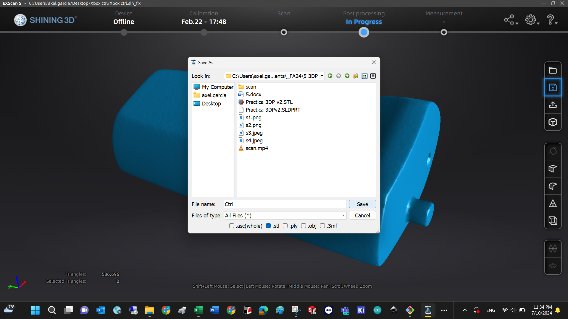
Post processing: once the mesh is complete, you just need to close some gaps in the mesh with the automatic tools, define how precise you want the mesh generation, and you can export your model in STL or OBJ format for 3D printing.
Measurement: use the tools if you want to estimate the value of its physical properties.
