4. Electronics production
This week I manufactured a PCB with the knowledge discussed in globally and locally: check out the Puebla FabLab repository: https://fabacademy.org/2024/labs/puebla/week4/
Preparation
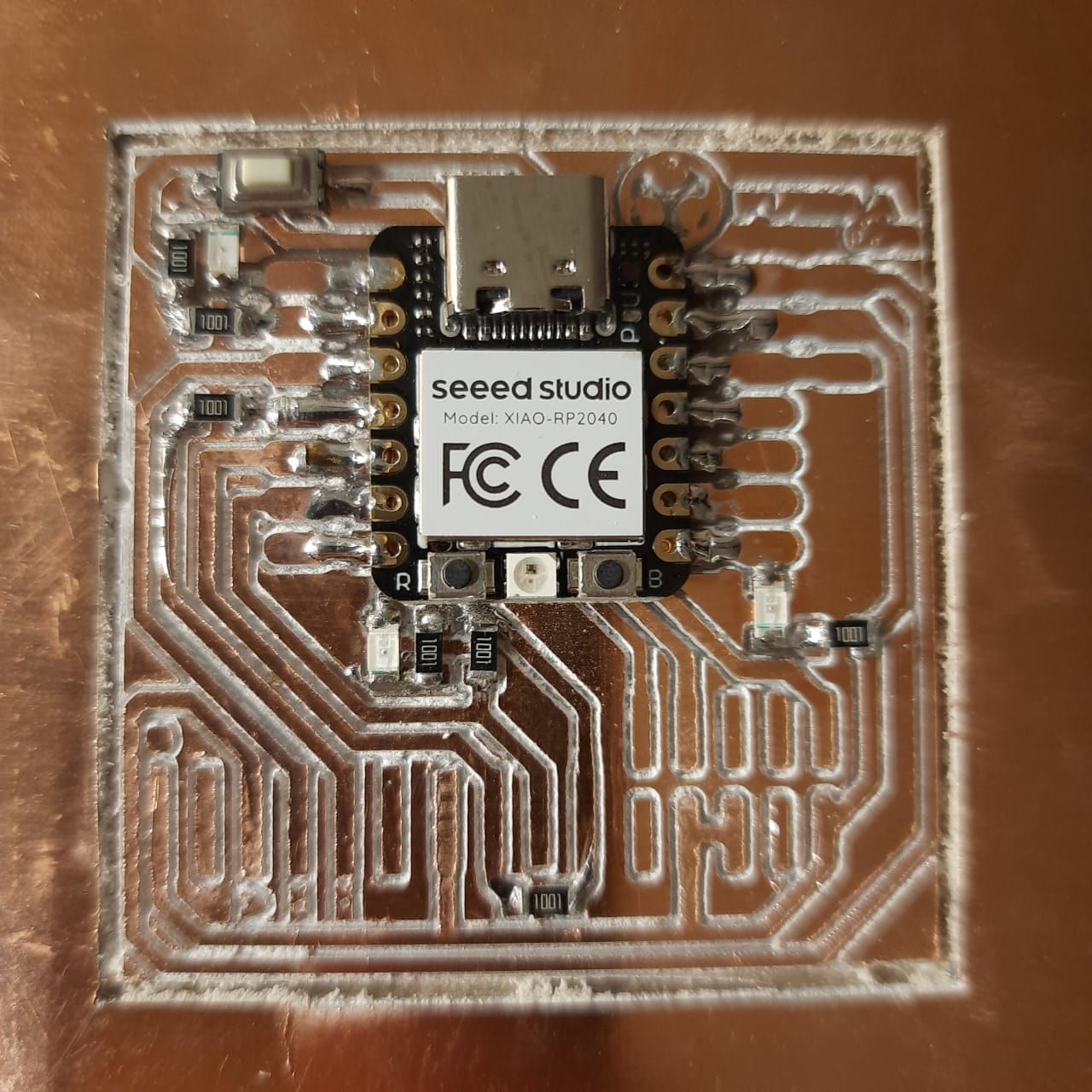
MATERIALS: Phenolic plaque, double-sided tape, push button x1, resistors x7, LED x3, XIAO RP2040, MDF support, USB-C cable.
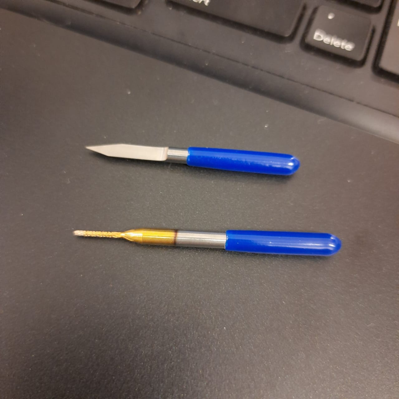
TOOLS: ROLAND SRM-20, V-cutter, Straight cutter, soldering station.
SOFTWARE: Mods CE server, V-Panel, monofabDriver_V180, Arduino IDE.
RESOURCES: PNG files, Teachers.
FAB PROCESS:
1. Software installation.
2. Code generation.
3. ROLAND setup.
4. Soldering.
5. Coding
1. Software installation
You must download V-Panel setup.exe and install. It’s also important to install the proper driver from the monofabDriver_V180 shared folder, in this case my system uses WIN10X64. The driver folder contains a program called SETUP64.EXE that needs to be executed and configured with “Install, Model: Roland SRM-20, and Port: USB”

2. Code generation
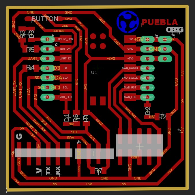
We must generate code for the traces (where the e-current flows) and also for the cut (to delimitate our circuit from the phenolic plate)
2.1 Traces code
You have to open https://modsproject.org/ right click programs/open program/Roland/SRM-20 mill/mill 2D PCB
Read png box: Select png file, tracespuebla.png
Set PCB defaults box: click mill traces.
Mill raster box: set offset number to 2.
Roland SRM-20 milling machine box: set x,y,z to 0.
Bottom switch box (linked to save file box): enable.
Mill raster 2D box: click on calculate button.
A new tab opens with the path, and the G-code is saved under downloads “tracespuebla.png.rml”
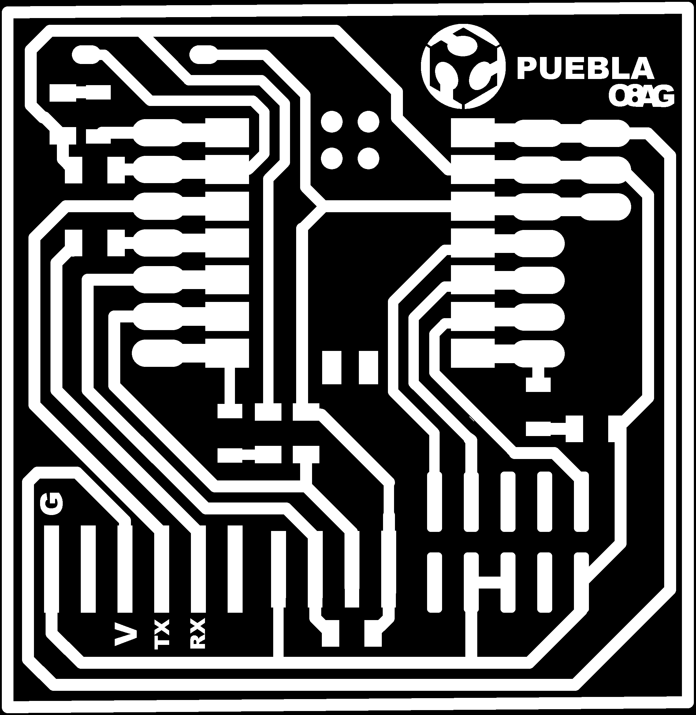
2.2 Cut code
You have to open https://modsproject.org/ right click programs/open program/Roland/SRM-20 mill/mill 2D PCB
Read png box: Select png file, cutouebla.png, invert.
Set PCB defaults box: click mill outline.
Mill raster box: set offset number to 1.
Roland SRM-20 milling machine box: set x,y,z to 0.
Mill raster 2D box: click on calculate button.
A new tab opens with the path, and the G-code is saved under downloads “cutpuebla.png.rml”

3. Milling machine setup
Power machine on.
Plug the USB comm cable.
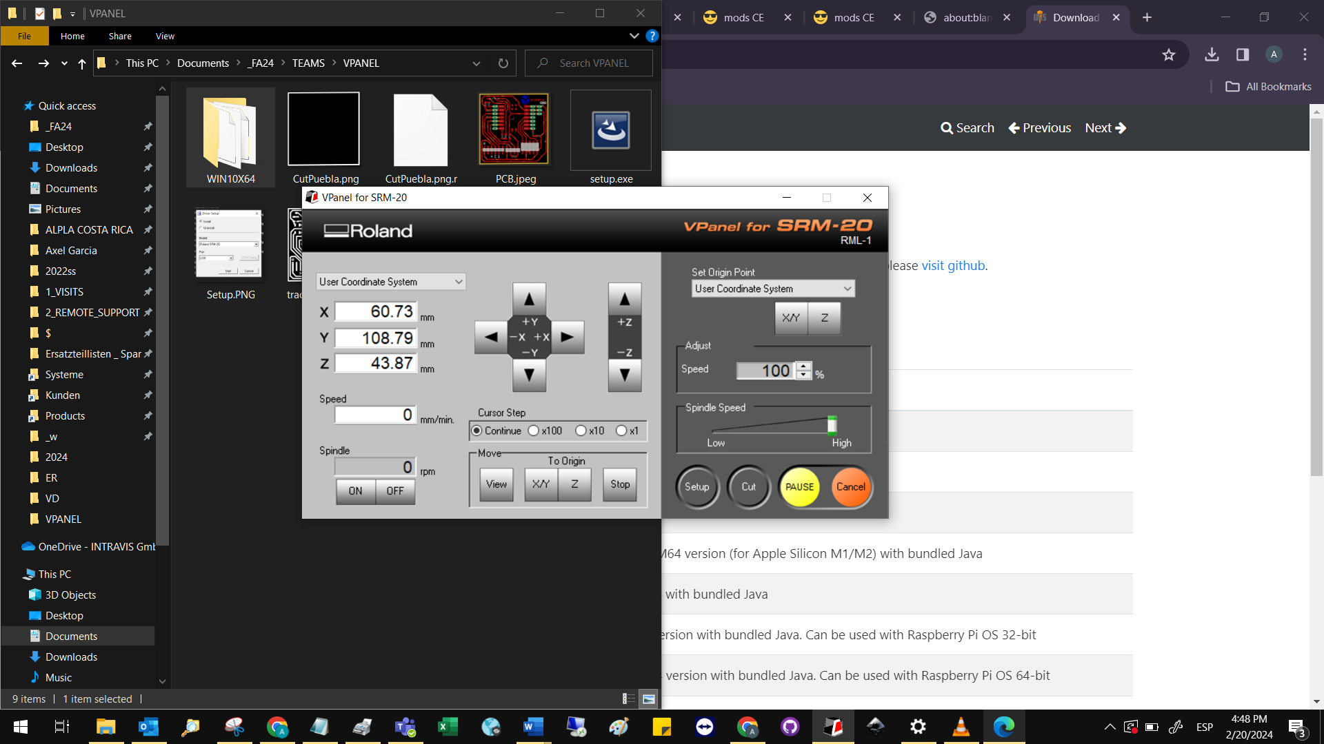
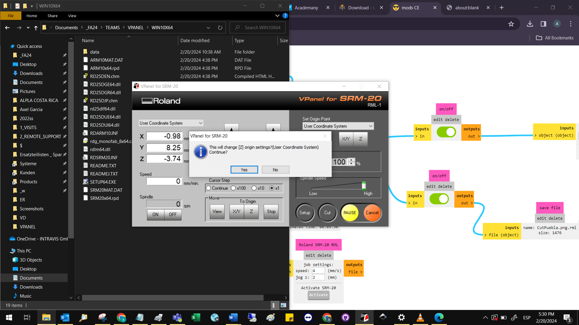
Open VPanel software (in my case I had to click retry connection to connect laptop and machine)
Click on the cut buton, select the traces file.
Glue the phenolic plaque to the MDF base as centered as possible, using double-sided tape. Make sure the double-sided tape covers all the bottom surface and that it does not stack on top of each other.
Open the safety cover. Screw the MDF base in the work position.
Place the V cutter in the spindle. Make sure that only the cylindrical part of the cutter is secured.
Use the arrows to move the X axis (left-right) and Y axis (depth) to the origin. The origin is recommended to be a point with coordinates 10 mm, 10 mm from the bottom left corner of the plaque.
Once you achieve the recommended origin, click set X/Y origin. Click continue and Yes.
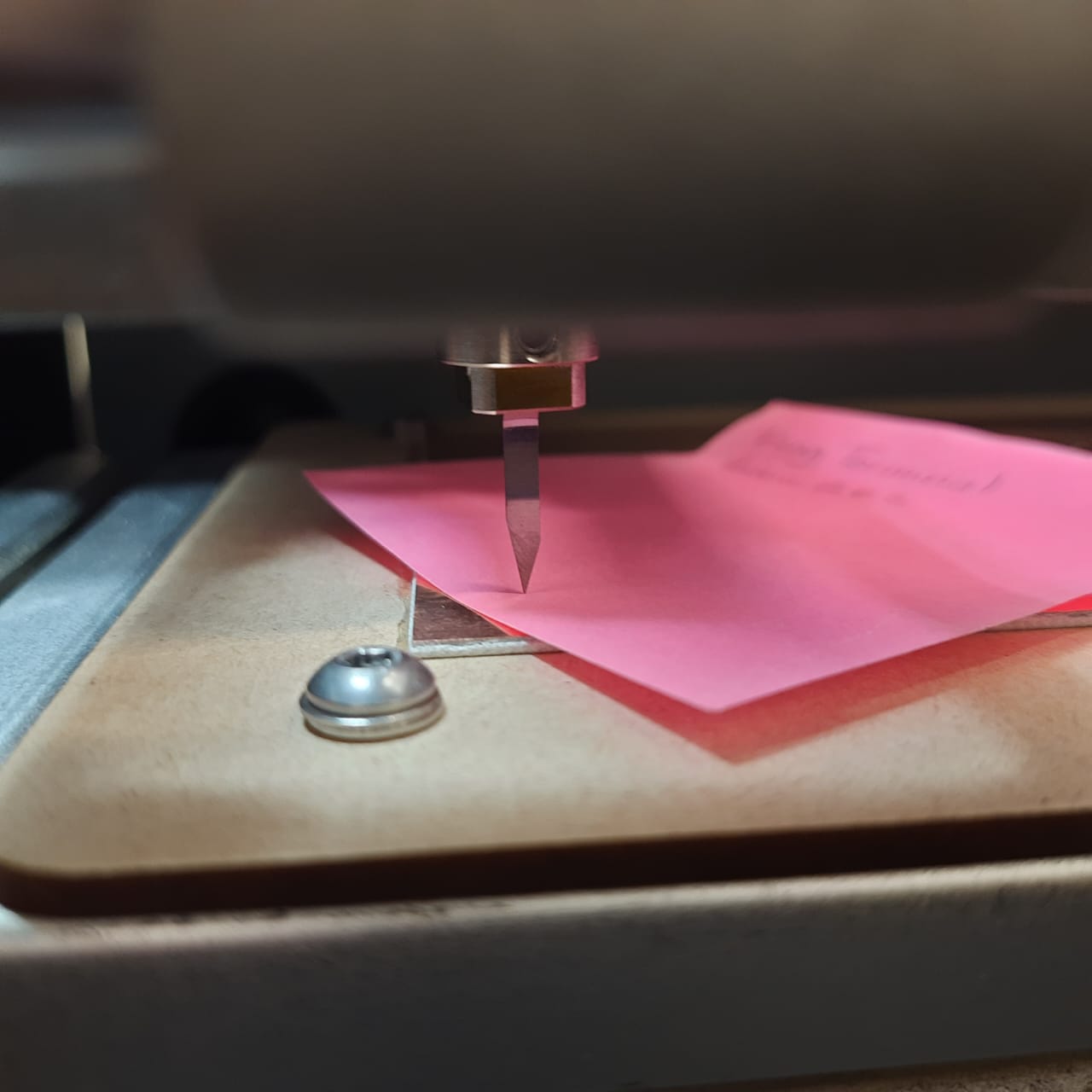
Then we must set the Z origin by changing the cursor step to x100 and x10 until the tip of the cutter applies friction to a post it, but not enough to prevent movement of the paper.
Once you achieve the recommended Z origin, click set Z origin. Click continue and Yes.
Close the safety cover.
Click on the Cut button, click Add button, select tracespuebla.png.rml, click Output.
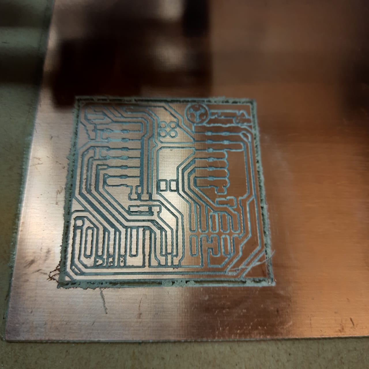
The machine will start milling, it’s important to hear a continuous vibration to indicate a proper continuous work. Else, it might indicate leveling or cutting tool issues.
Once the traces are done, remove dust with vacuum, avoid touching and inhaling, and verify the proper milling of the traces.
Change the tool to a straight cutter, set a new Z origin, load cutpuebla.ong.rml, output to start cutting.
After the cutting cycle, please clean your working area and leave the machine/tools ready for use.
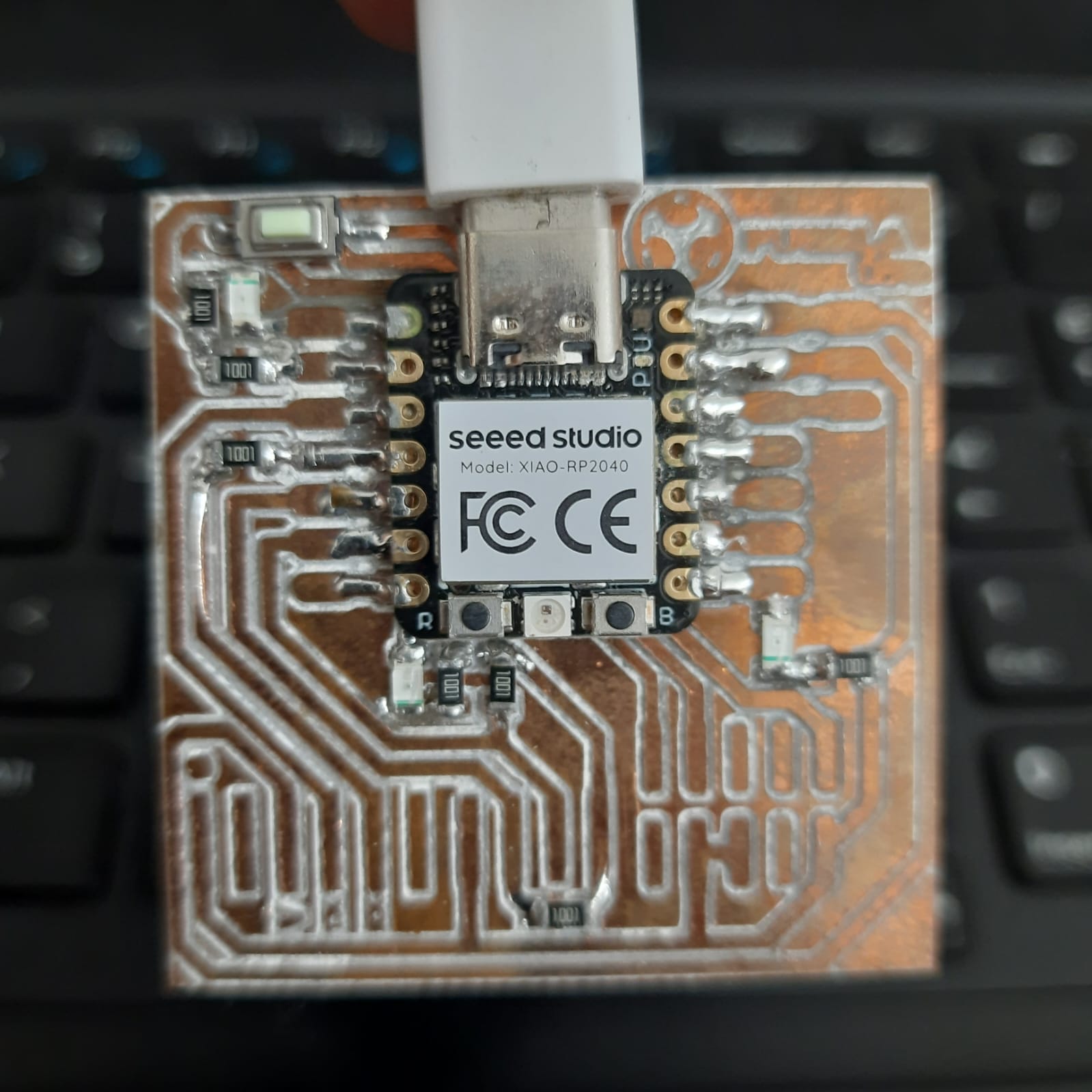
4. Soldering
Prepare your working area by removing any hazardous condition.
Have your e-plan, references at hand for comparison and guidance.
Start by soldering the biggest components and ending with the smallest ones (Xiao, push button, LED, resistors)
In my case, I set the temperature to 300°C, apply heat to the traces, then slowly approach the component terminal, without taking the tip of the soldering iron off.
Soldering big components: slowly apply a medium amount of welding material to the tip of the soldering iron to cover terminal and trace at the same time.
Soldering small components: apply a minimum amount of soldering material to the traces. Then place component in final position and heat the trace, then the terminal to fuse materials.
Avoid touching the electrical components with the soldering iron for a long time.
5. Coding
Download and install Aruino IDE.
Download the.ino file to be loaded.
Connect the USB cable to the board.
Select board in Arduino IDE.
Compile.
Test.