3. Computer aided cutting (CAD)
Week asignments
1. Group assignment: do your lab's safety training.
2. Characterize your lasercutter's focus, power, speed, rate, kerf, joint clearance and types.
3. Individual assignment: cut something on the vinylcutter.
4. Design, lasercut, and document a parametric construction kit, accounting for the lasercutter kerf, which can be assembled in multiple ways.
Safety training
Wear safety glasses, tight clothing, no jewerly, use facemasks when working with gas or dust, better to work supervised or with at least one partner, ask questions when in doubt.
Lasercutter characterization
Check out the Puebla FabLab repository: https://fabacademy.org/2024/labs/puebla/week3/
Vinylcutter
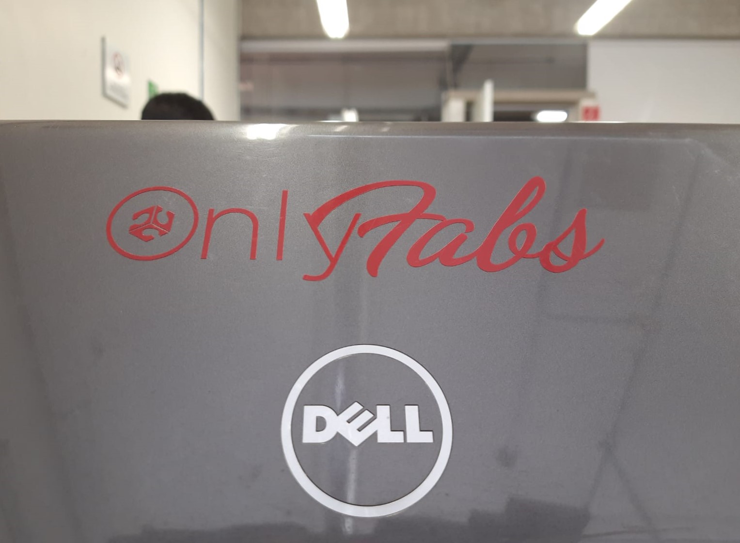
The design might be a little controversial, but I think this is quite hilarious. This is the result, thanks @heidi for the help with the design:

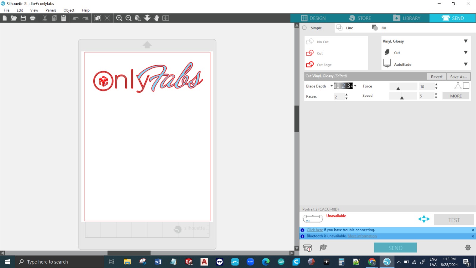
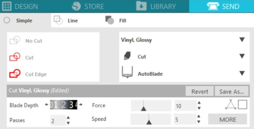
SILHOUETTE CRASH COURSE
Download and install software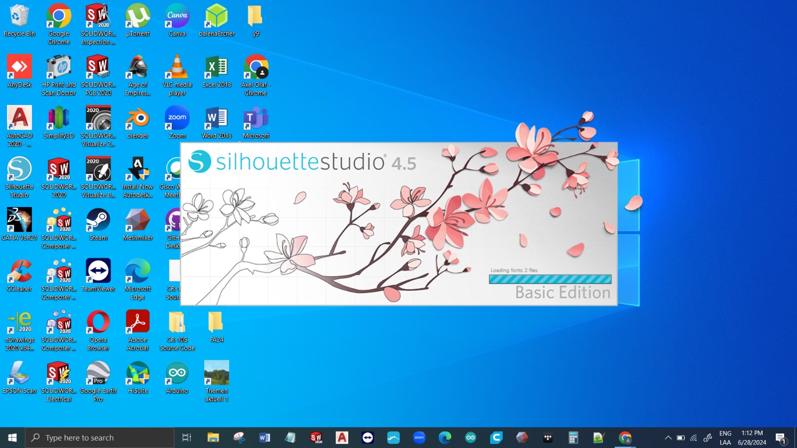
Cut a piece of Vinyl that fits inside the Mat working area (use tape to hold it)


WHAT CAN I DO WITH MY NEW STICKER?
If you have a place to do it, stick the hell out of it. Since the model is quite complex and tends to move, we should use the transfer tape. I was too excited to capture the pics, but the overall process goes like this:
1. Remove the material that’s not part of your design (Weeding; not 420 related)
2. Apply the transfer tape. Transfer tape is similar to masking tape but has a different tack for adhering to your vinyl but releasing it on the target surface. Use a semi-transparent transfer tape to apply your graphics.
3. Clean your target surface for better adhesion.
4. Peel the transfer tape away from the release liner and your graphics should come with your transfer tape. If they don't, push the transfer tape back down and use your squeegee again to stick the transfer tape to the decal. Take this decal and apply it to the target surface. From there, use your squeegee with a felt sleeve to smooth your decal on your target surface removing all air bubbles.
Parametric construction kit
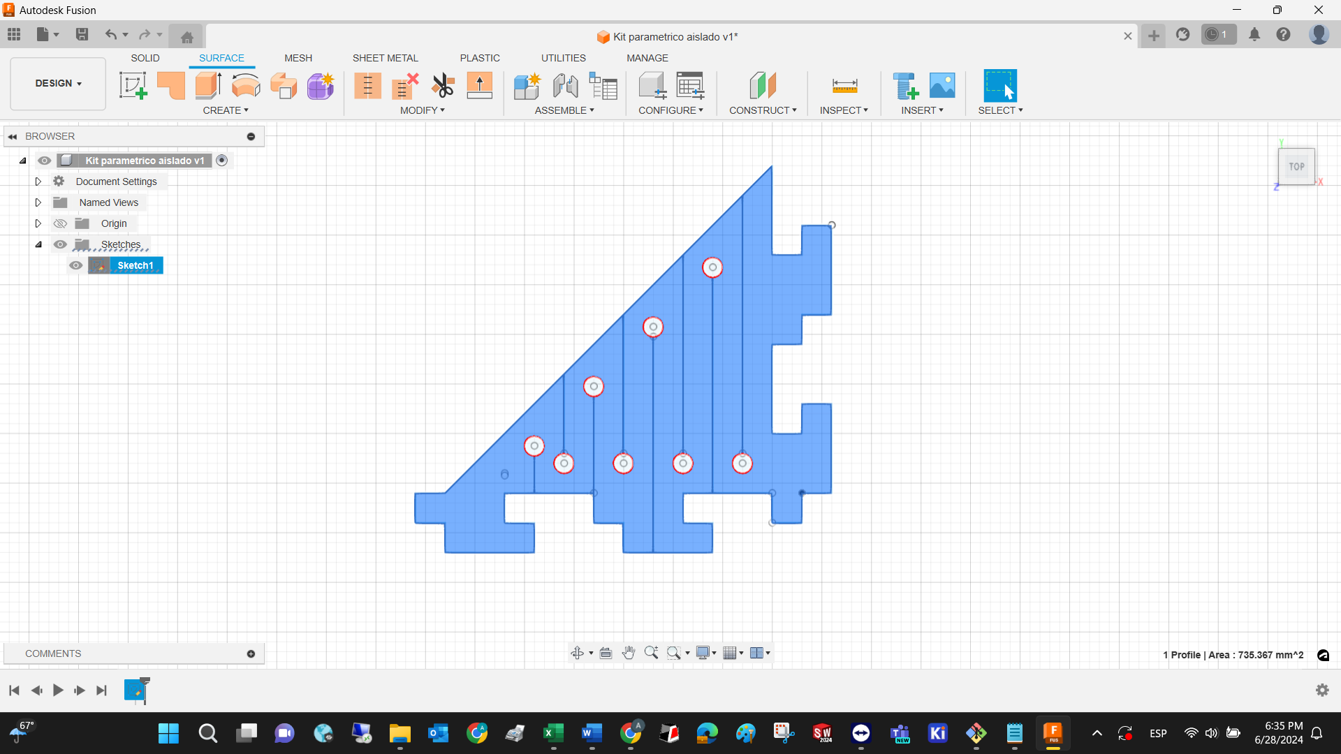
The first iteration of the parametric construction kit was inspired by the Chinese version of some toy construction blocks. They can be stacked on top of each other, and they can be attached laterally due to the geometry. This is how the sketch looks like:

My version of that design was made in Fusion. In the image above, the dimensions of the sketch are expressed in units. Each unit is represented by the material thickness. To make it flexible, I added some lines and holes, the latter element may be expressed in terms of the thickness.
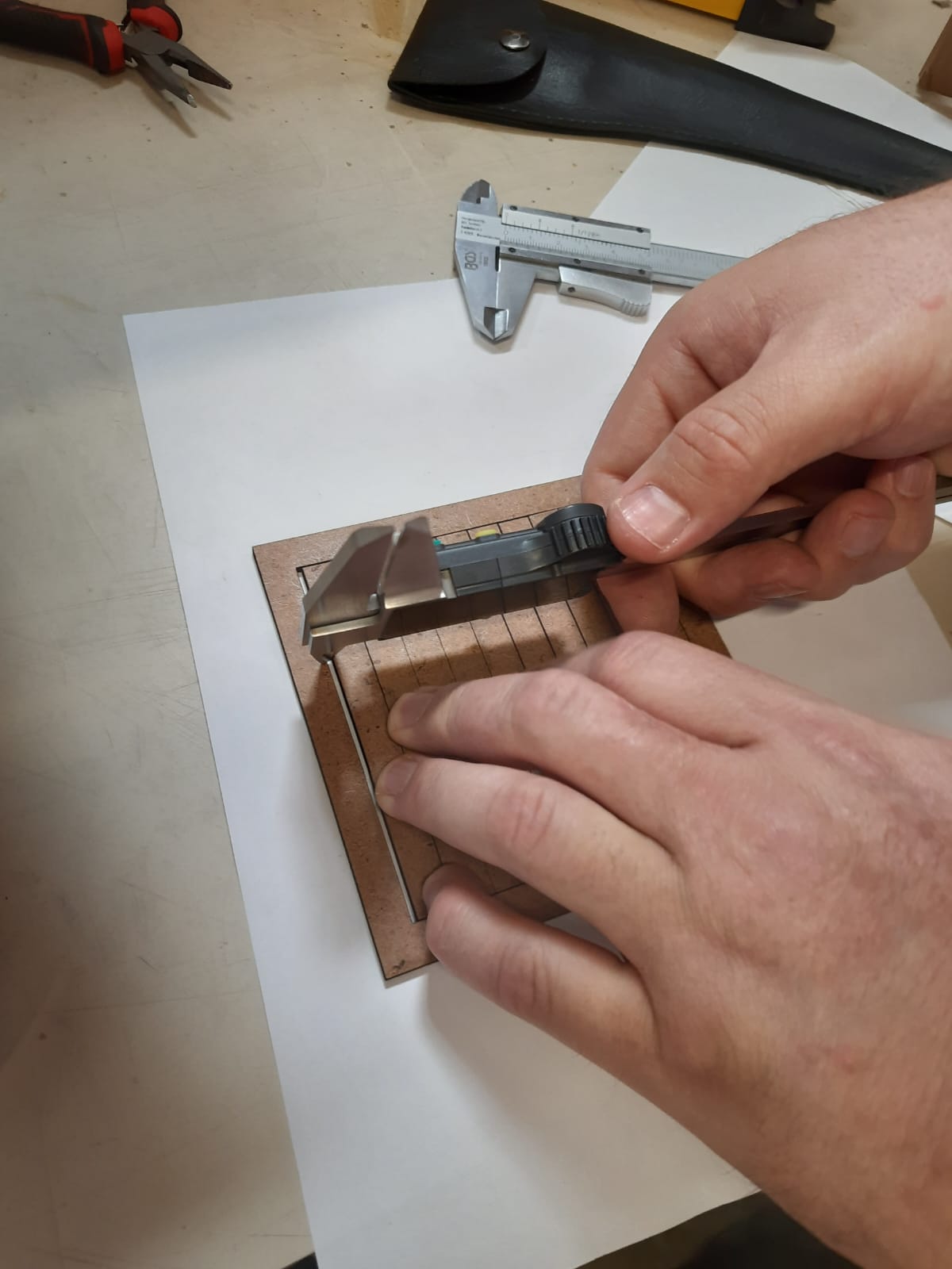
Due to the nature of this manufacturing method, a kerf must be measured and defined to have perfect mechanical adjustments between elements. In this case, I made part of the assignment at Ibero Santa Fe, and they have a different machine. I designed a square that contains 10 rectangles.
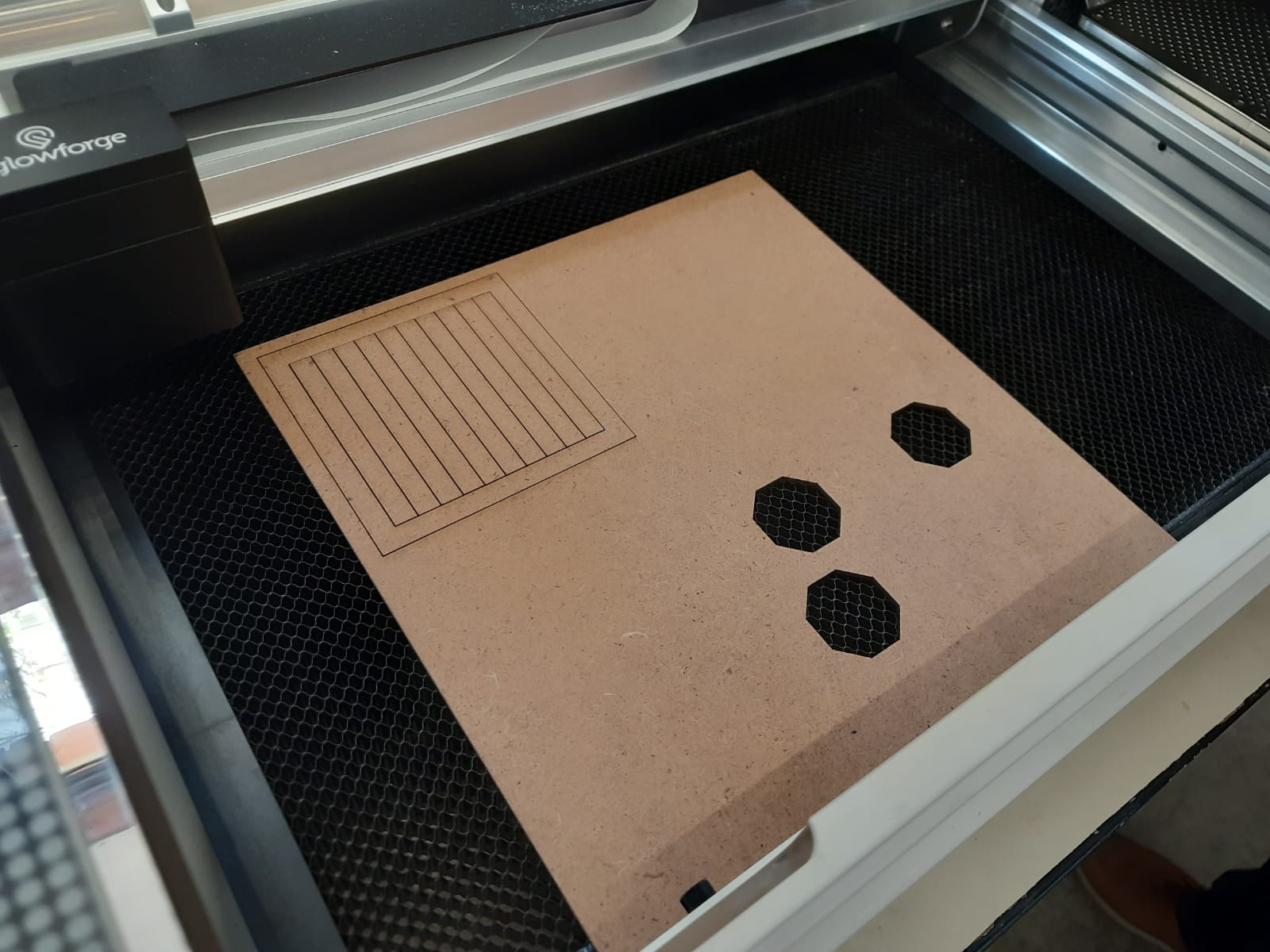
Some parameters used in the cutting of this model and this particular machine are: Speed meassured in mm/s, % of laser power, considering that this machine works with 45 Watts, and number of passes (ideally 1)

After laser cutting it, you just need to measure the space between the last rectangle and the square, then divide that by the number of rectangles + 1. The kerf measures 0.125.
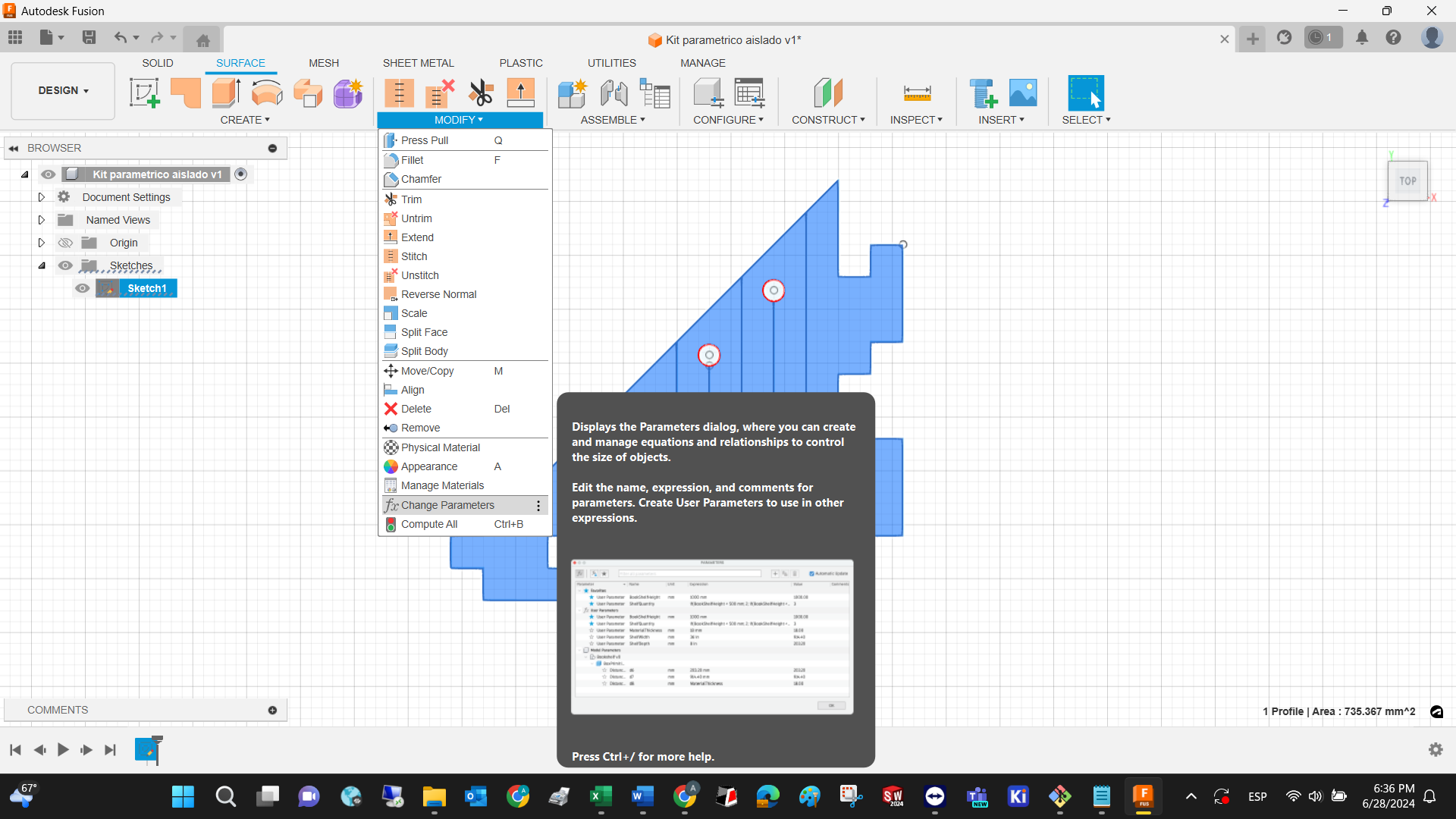
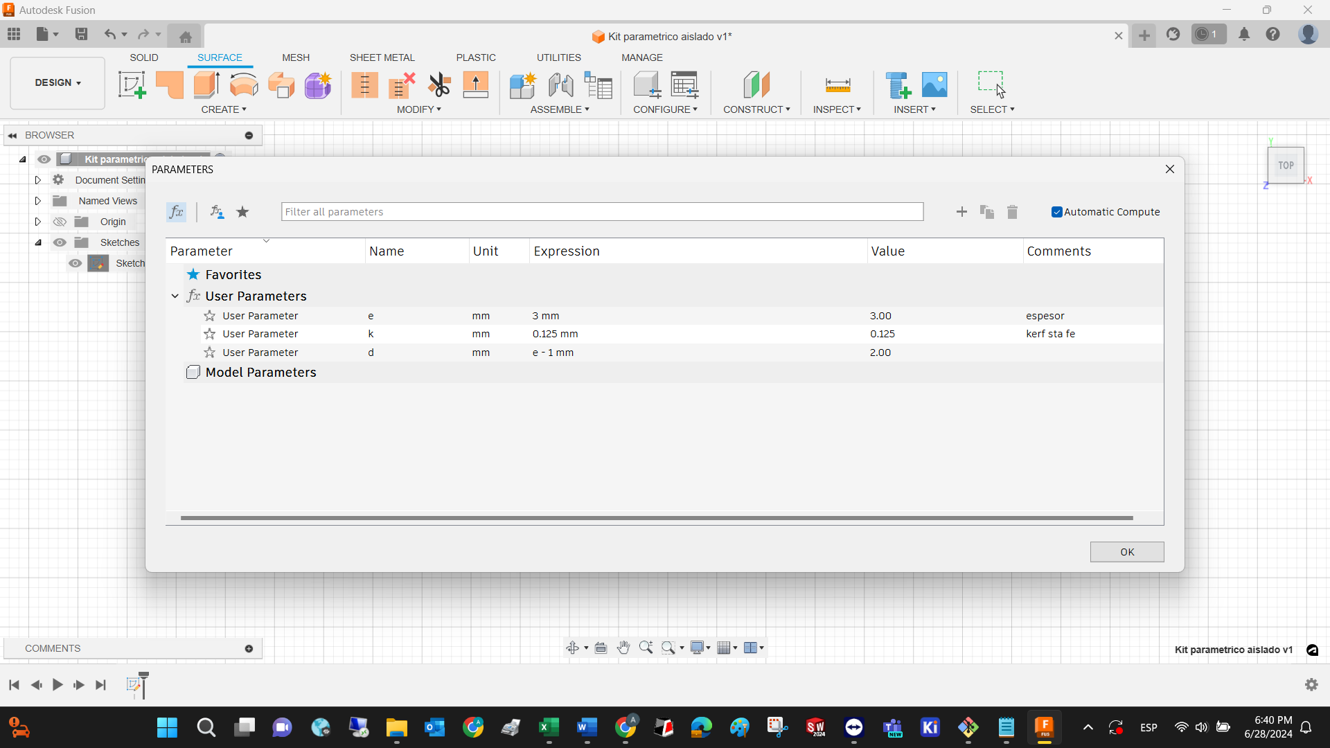
To use the previous information into a parametric design, the first thing you need to do is, declare each parameter in the following section:

All of the final parameters looks like this:
Since this design is made of lines, you just type the name of the parameter instead of typing the value of the length of each line:
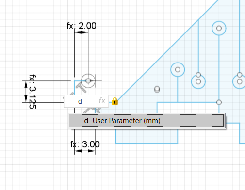
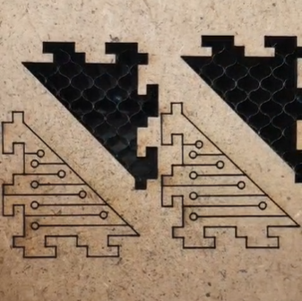
The final parametric 2D design looks like this:
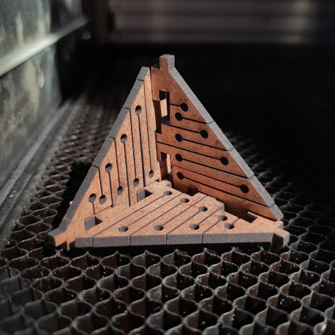
Laser cutter and manufacture:
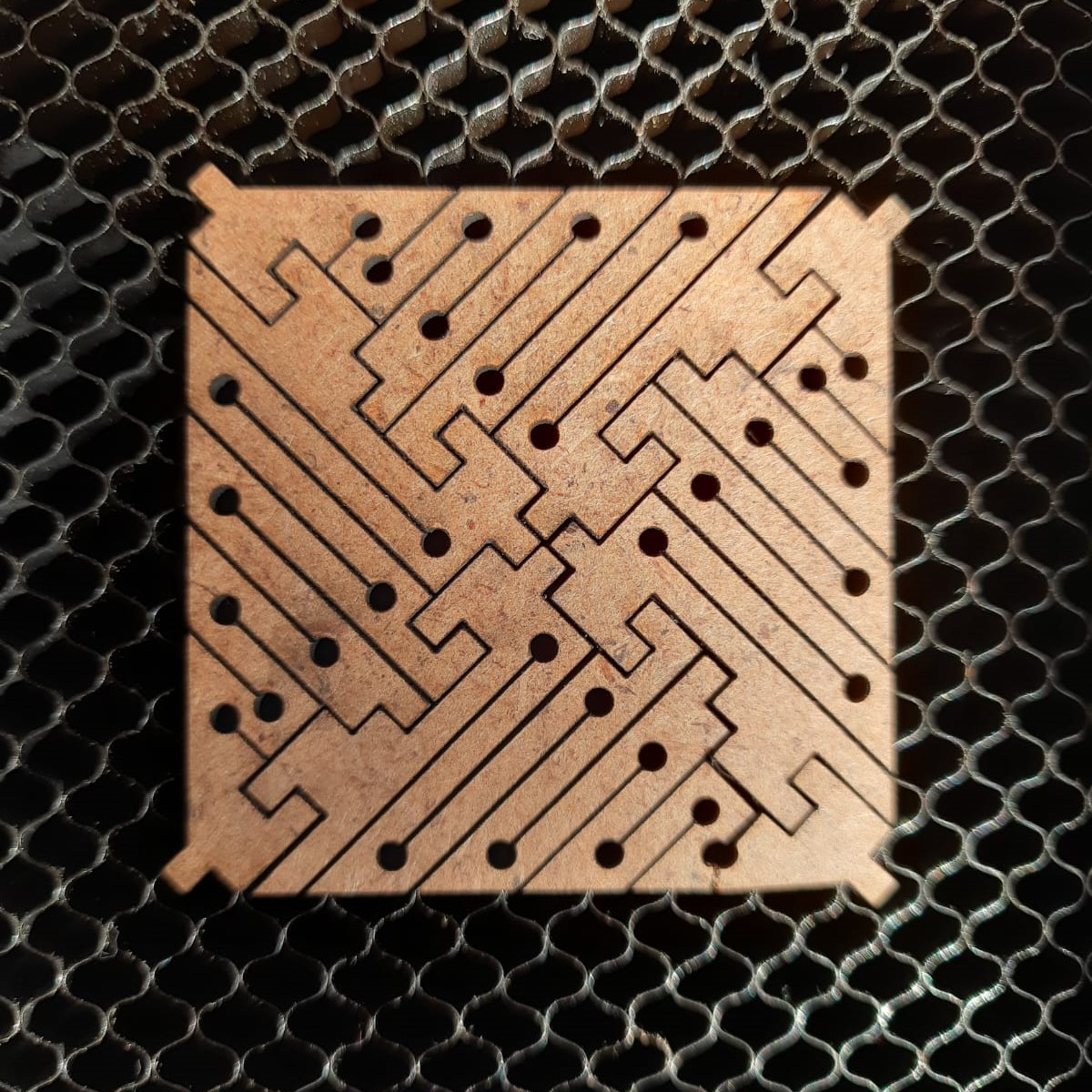
This is the individual piece and all the ways to assemble them: