2. Computer aided design (CAD)
Week asignments
1. Model (raster, vector, 2D, 3D, render, animate, simulate) a possible final project
2. Compress images and videos
3. Post a description with your design files on the class page
Model of the possible final project
Basically, we need to start by defining the final project: it is defined here: link to final project.
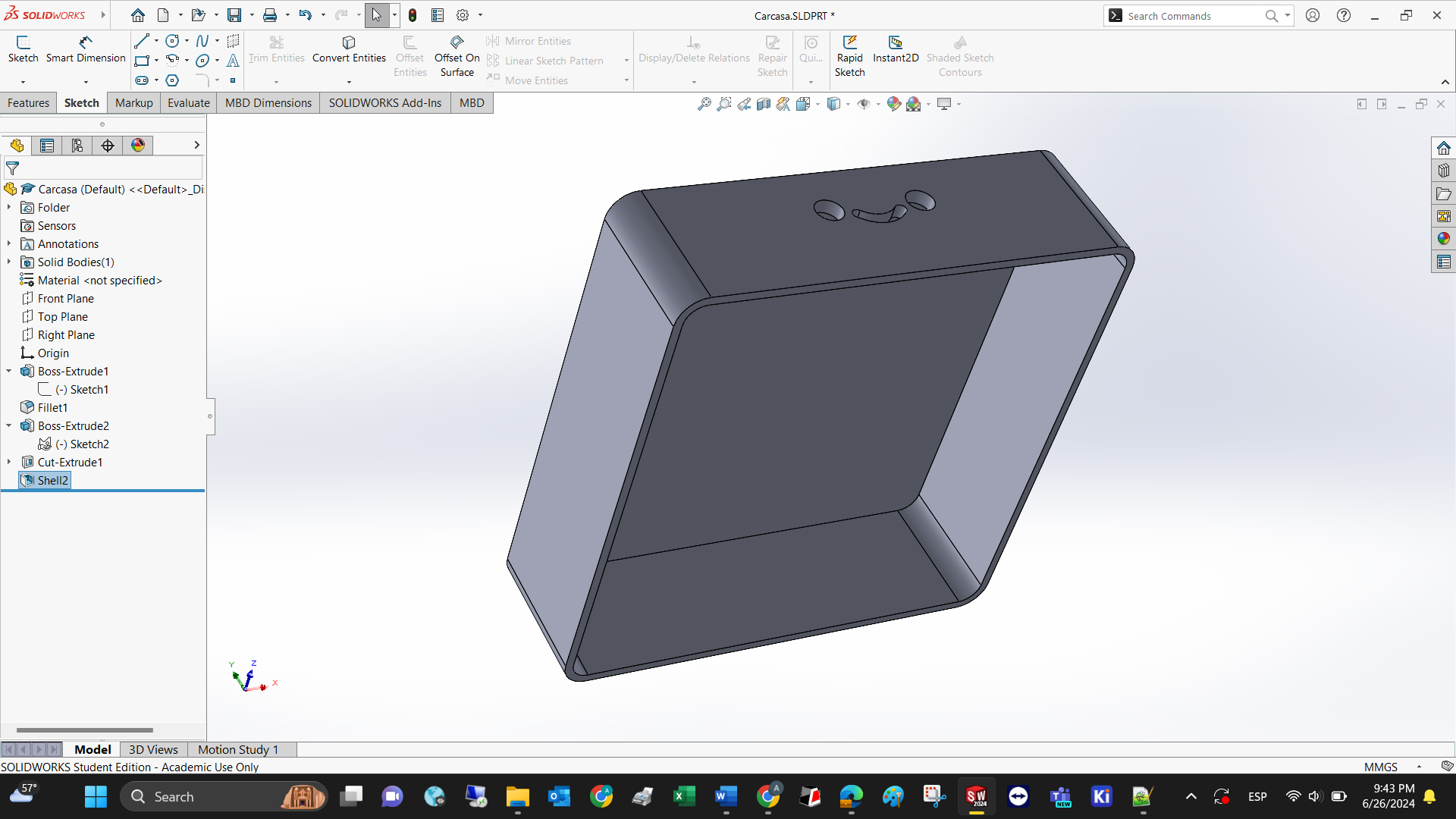
I can visualize a box with a height below 55mm, and a square area below 180 mm per side. Also, a smiley face in the front to distinguish the front part of the device.
The Fab Academy provided us with Fusion 360, but I don’t have time to master it. Therefore, I’ll be using SolidWorks for the rest of the course.
Like every CAD software, you need to follow the next steps:
1. Create a file or project.
2. Set the measurement units. I’m team International System of Units (ISU), but a colleague from work told me that there are only 2 types of countries: the ones that use ISU, and the ones that have reached the moon (Imperial Measurement System, IMS) God bless America!
3. Select a plane to draw a sketch.
4. Draw a sketch (parametric or not)
5. Turn the sketch into a 3D object using the 3D tools.
6. Draw a new sketch on one of the flat surfaces (planes) of your new 3D model.
7. Repeat until you’re happy with the final result.
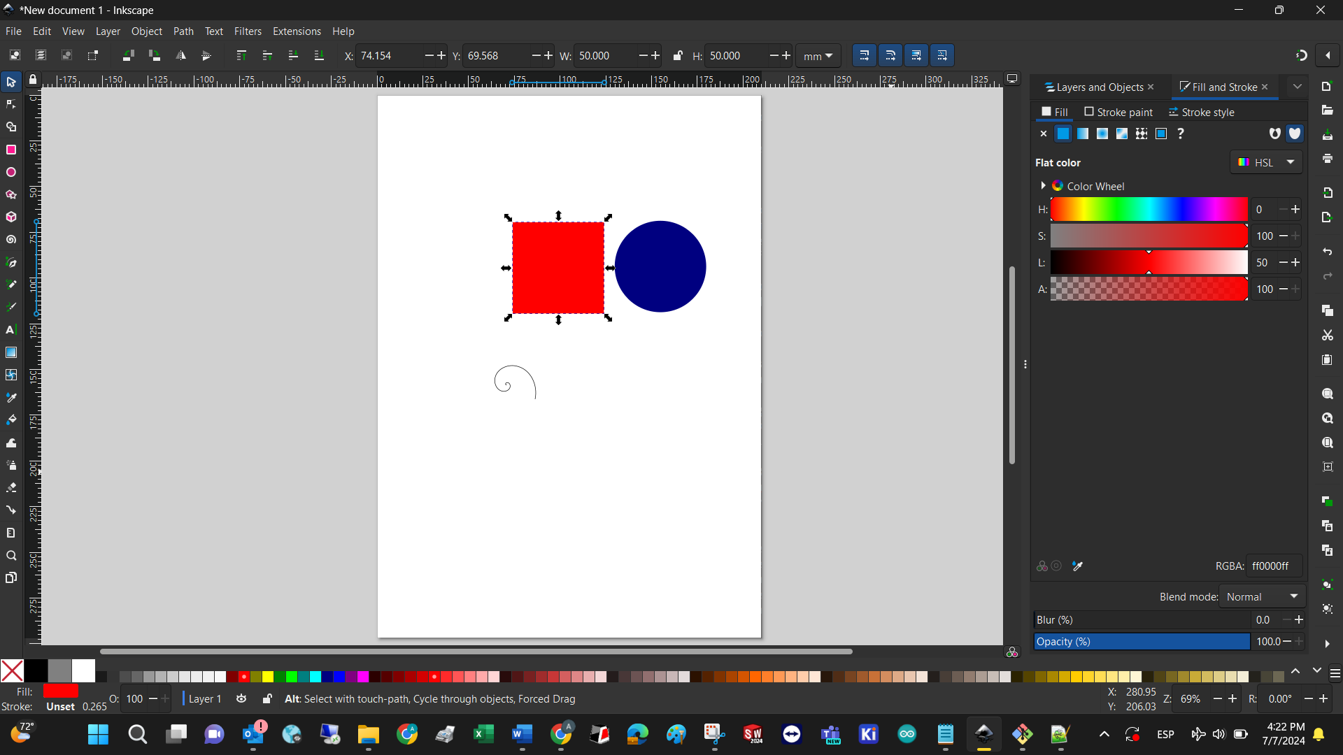
INKSCAPE
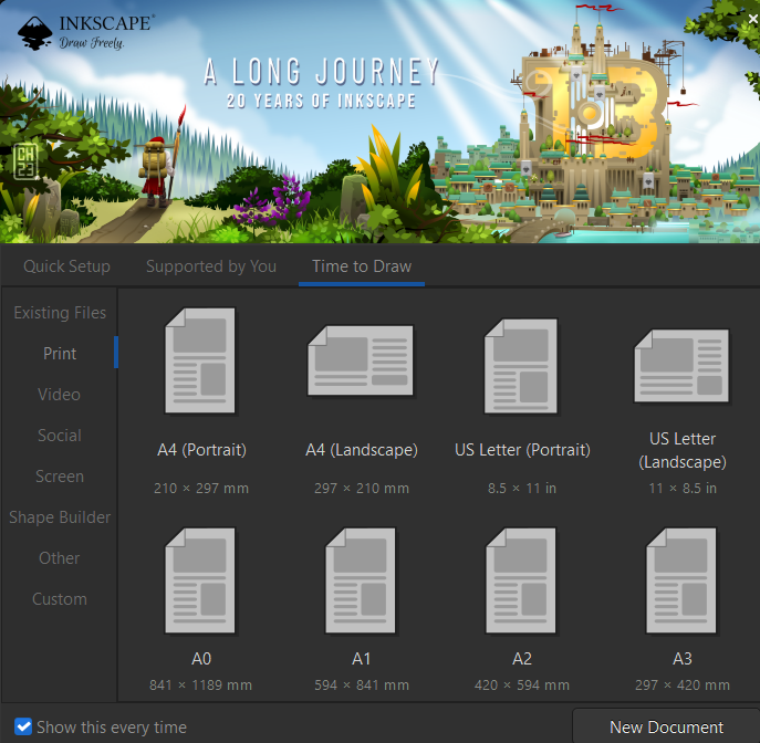
Let’s assume that you have downloaded the software and installed it. The newest version has a quick setup to select the kind of document you want to design with standard measurements. You can always change the canvas size afterwards.
The canvas has been created and now you can add standard figures like regular and irregular polygons, circles, squares, etc. You can also add images and edit them.
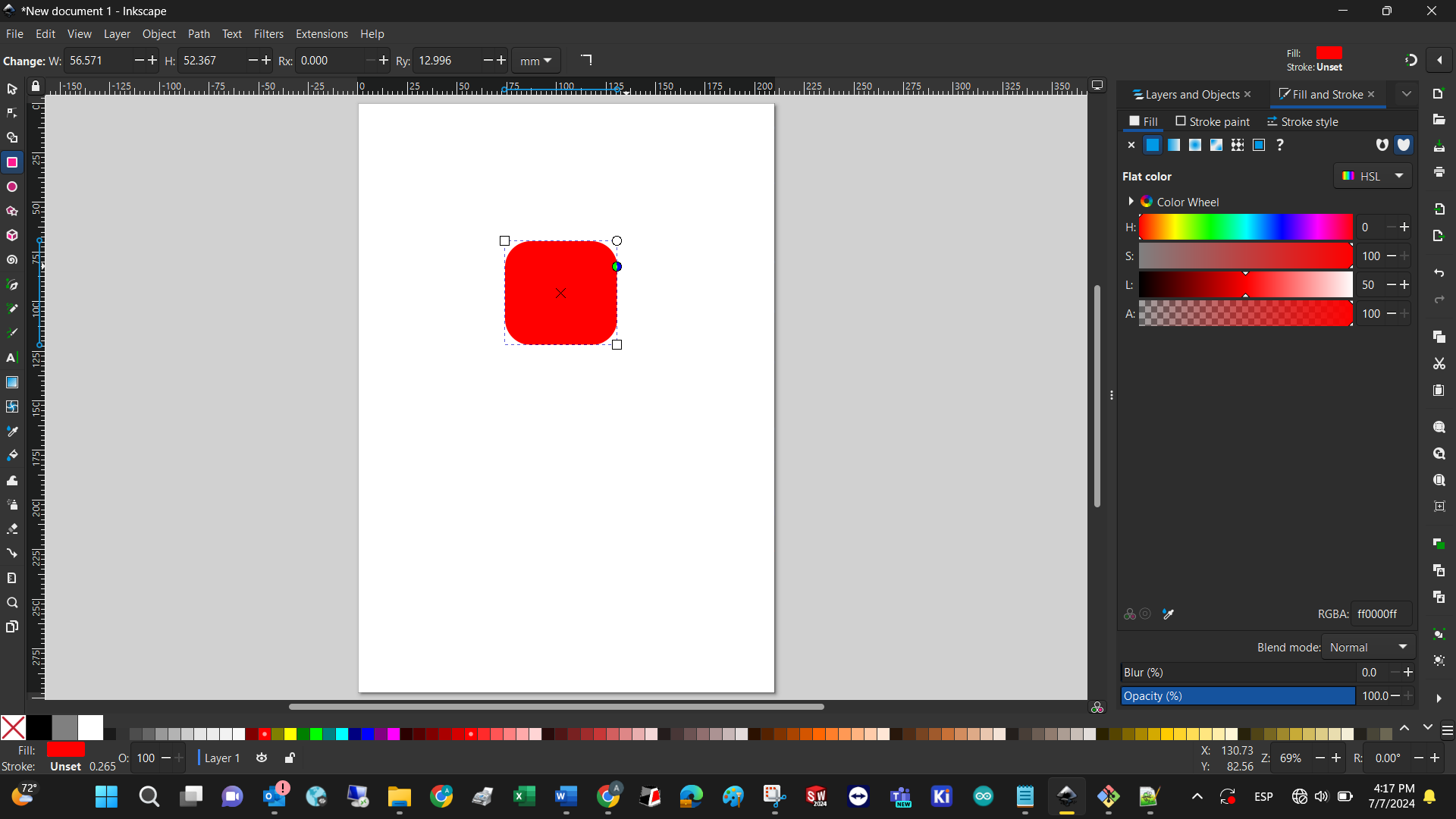
After creating a document and adding a square, you can change its properties like perimeter color, area color (All visible from the bottom bar), edge roundness (by dragging the small circle on the upper right corner of the square), size (you can either drag the figure vertices or specify a specific value for Width and Height in the upper bar of the software).
Finally, the position of every figure can be changed by dragging the figure within the canvas, or by selecting the figure and specifying its cartesian position in the upper bar (X, Y)
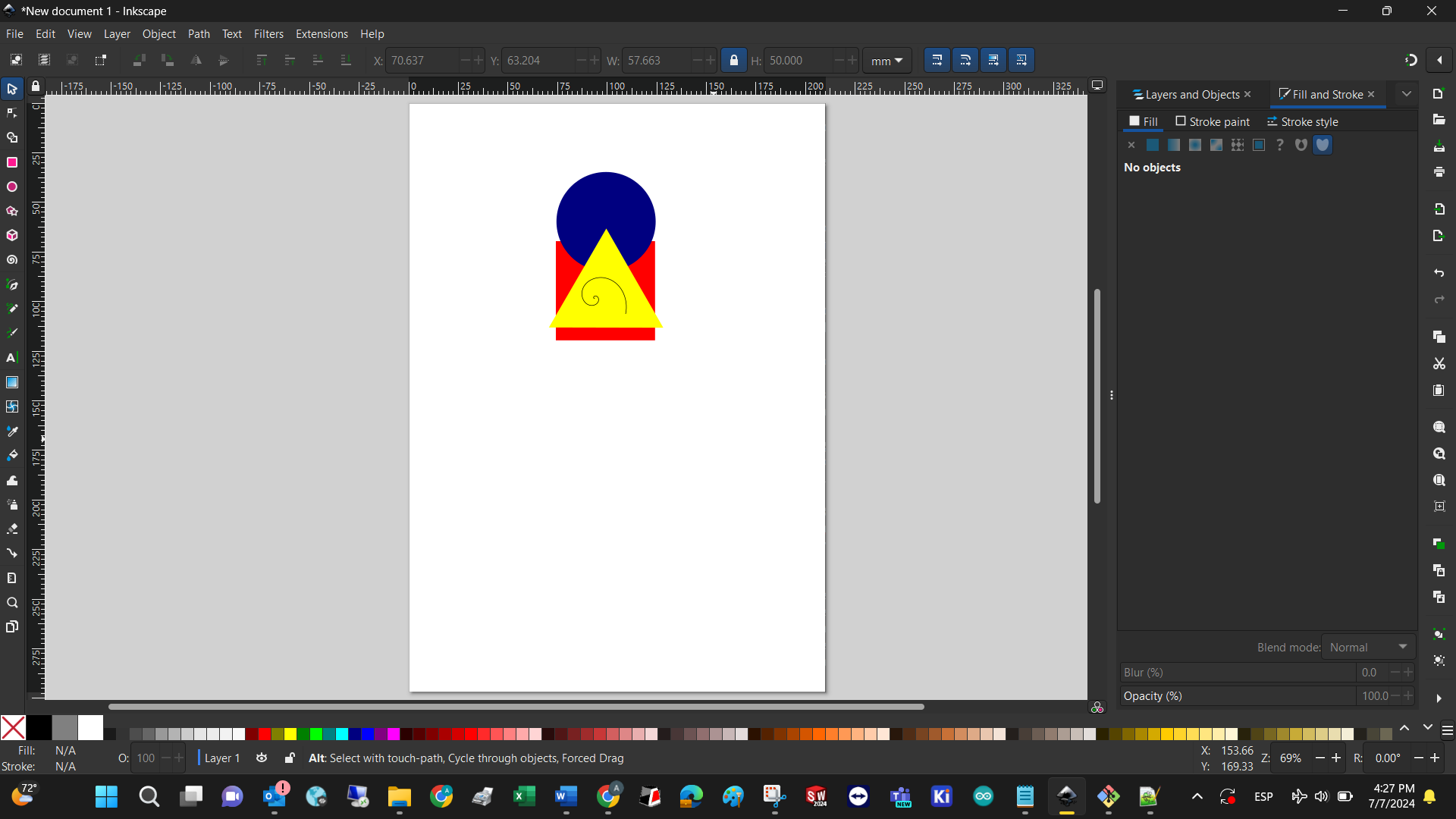
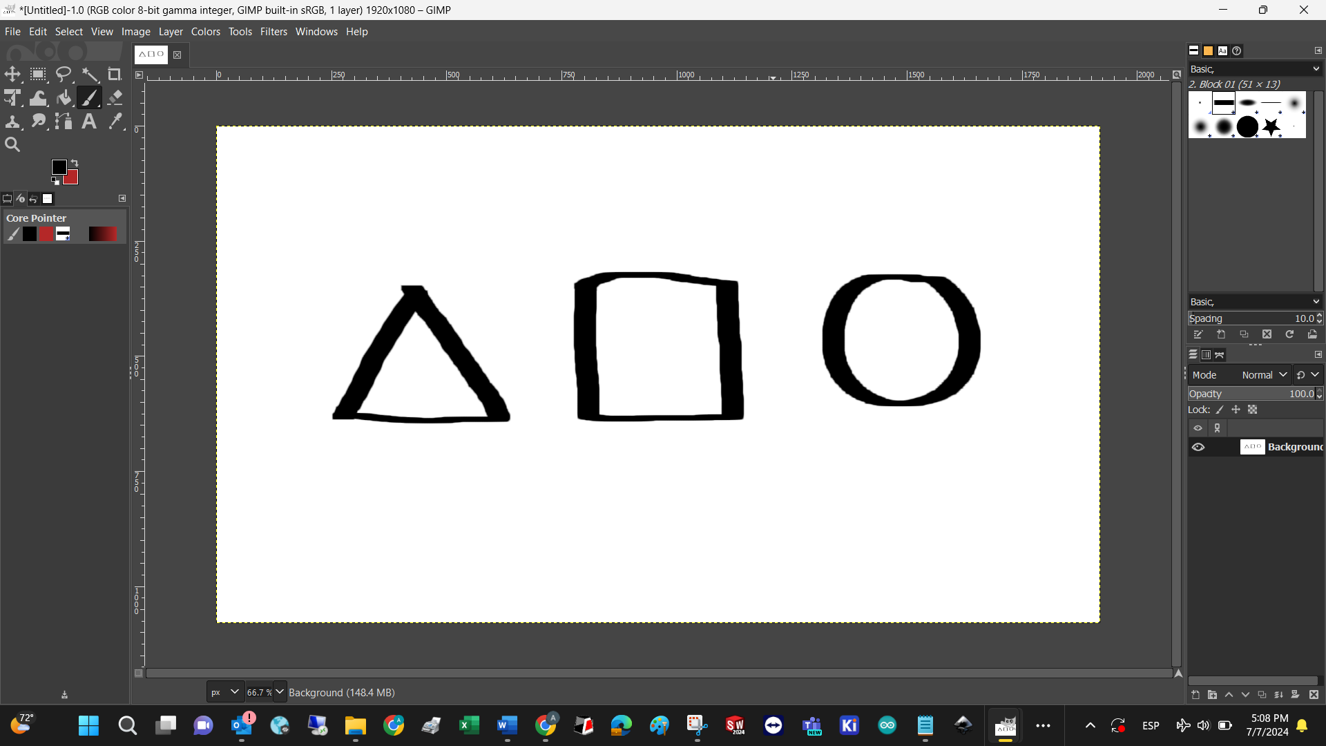
Since I’m currently reading about the Bauhaus, I’ll create the basic forms: yellow square, red rectangle, and blue circle. Basically you just have to select each figure in the left hand bar, set the perimeter color to blank, and change the infill color respectively. Finally, adding a spiral and experimenting with position ended with this model as an output. Might as well be considered modern art!
When you save a new drawing, its extension is .svg since this software is designed to work with vectors, but after saving it´s possible to export the .svg to many other file types.
GIMP
The installation and execution of the software needs a lot of computational resources, that is manifested in terms of time.
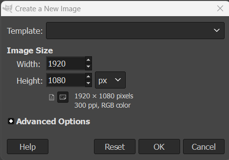
The first step is to determine the template properties
The interface is completely different from the ones I know, and that has to do with the fac that this program has a focus on editing images, not creating them.
The only tool I could use to repeat the Bauhaus exercise was the freehand marker.
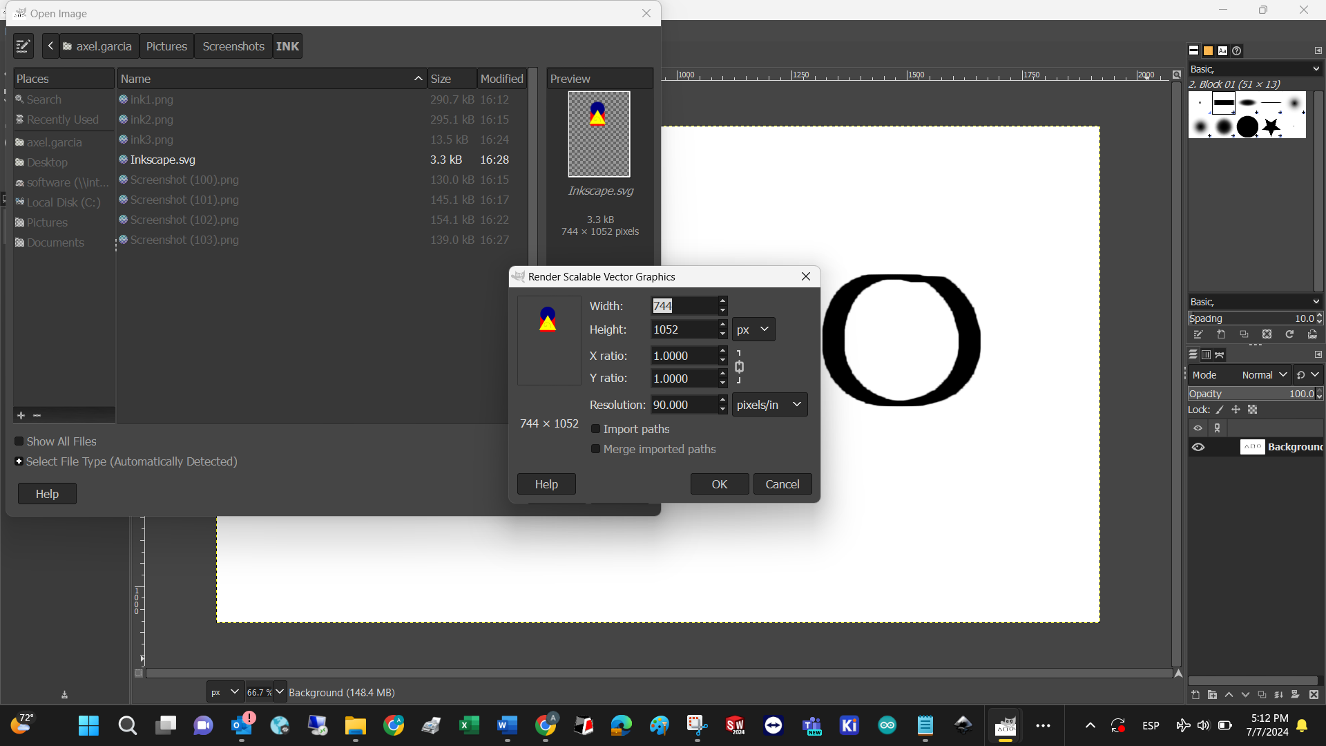
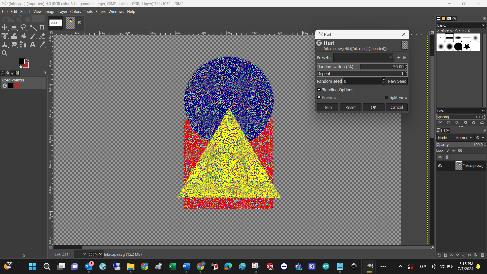
In my opinion, the most powerful tool in this software, is the filter feature. Which has a wide range of them for scientific and artistic purposes. I invite you to explore them all. To test said properties, I imported the image done with Inkscape using the following workflow:
The result resembles the Windows Paint art that I created when I was a child.
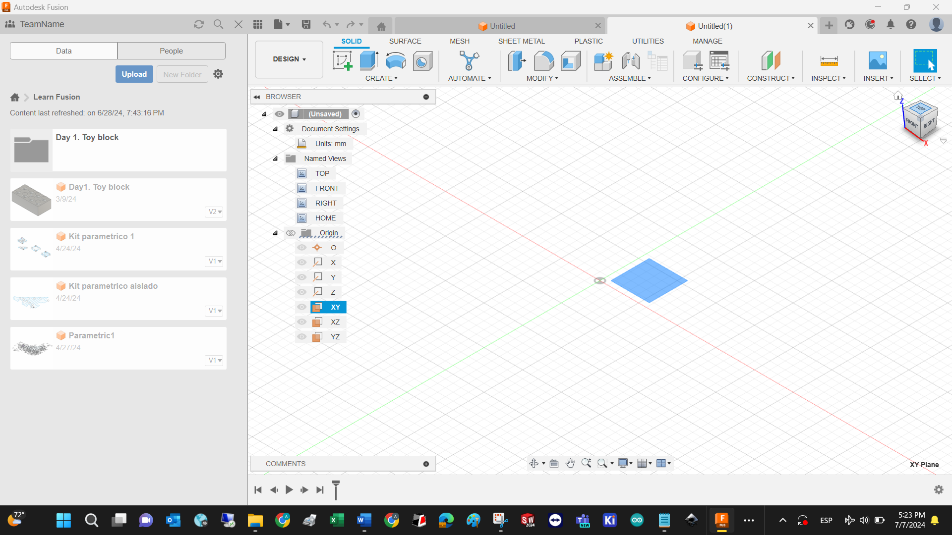
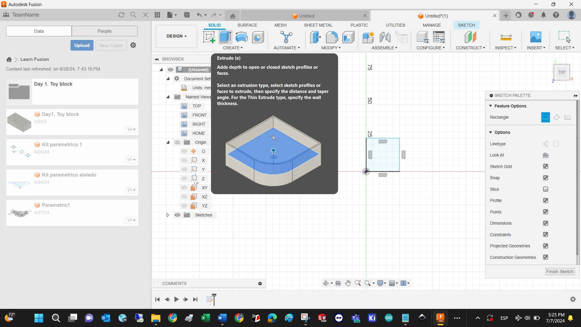
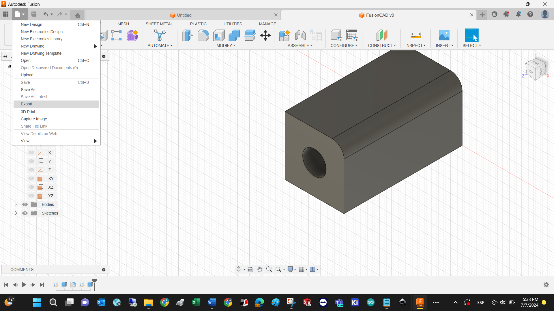
FUSION
Open software after downloading and installing. Thanks Fab Foundation for the licenses!
Create new design by going to file/new file, or pressing CTRL + n
Select working plane on the left tree. Notice that Fusion uses XY, YZ, XZ instead of top, lateral, and front views in SolidWorks.
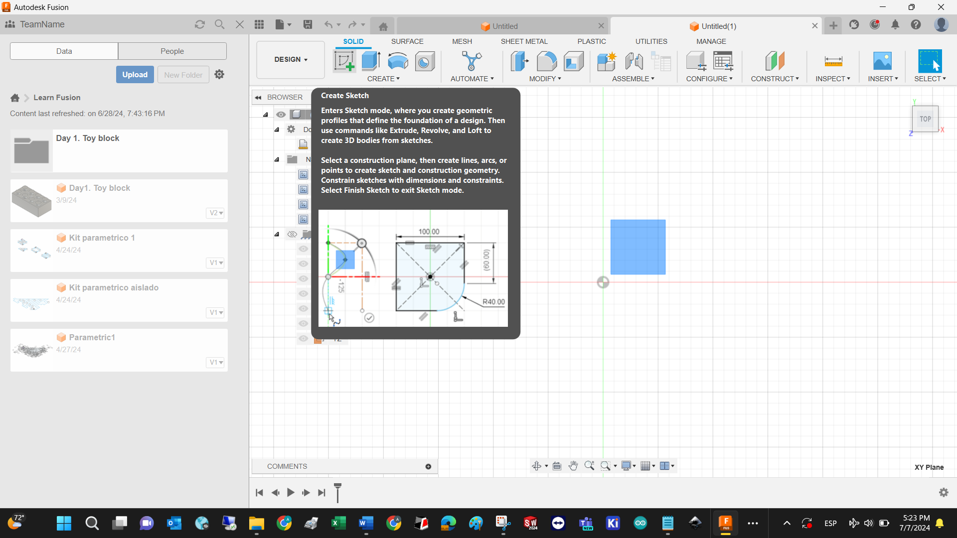
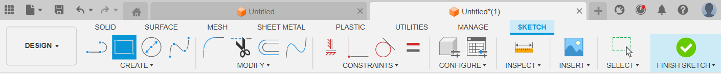
Create a sketch in the selected plane, and consider all the sketch tools available. I encourage you to test each one of them.
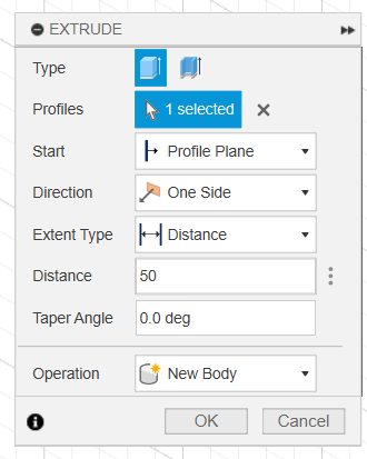
Extrude the sketch to turn a 2D image into a 3D shape
Define the extrusion distance
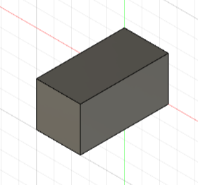
This is our first 3D model with Fusion
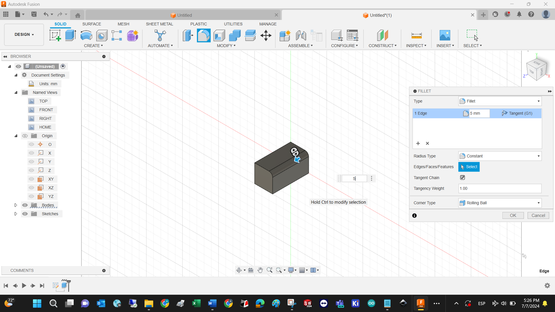
Another very used 3D tool is the fillet, which cancels sharp edges and makes design better real quick.
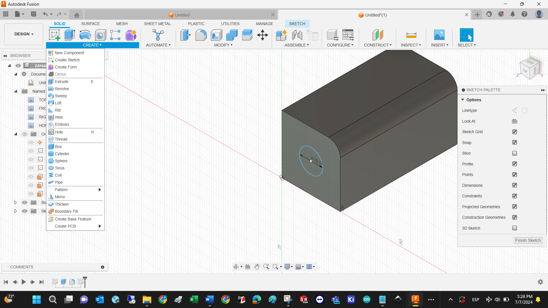
Cut extrusion: select plane from the 3D shape
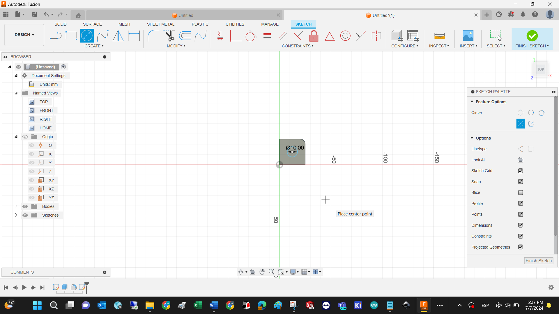
Draw a sketch on the selected plane
Determine Extrusion operation (cut) and the distance
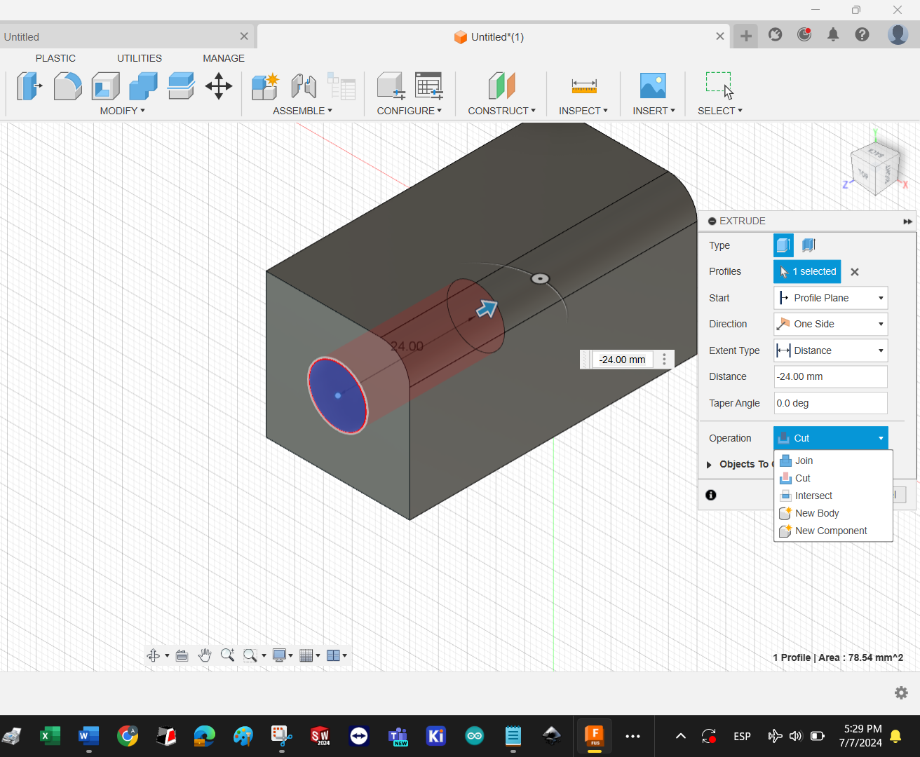
Result with minimal operations
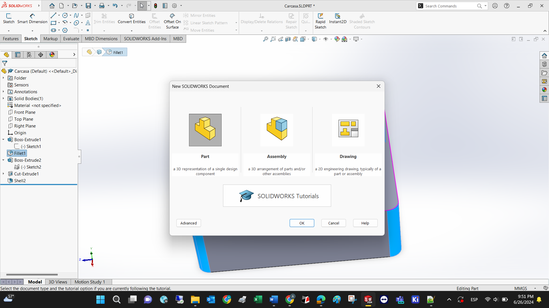
SOLIDOWORKS
There are 1000 better tutorials than the one I’m about to show, but a tiny introduction to the interface and capabilities doesn’t hurt. The basic workflow for designing a 3D model in SolidWorks goes like this:
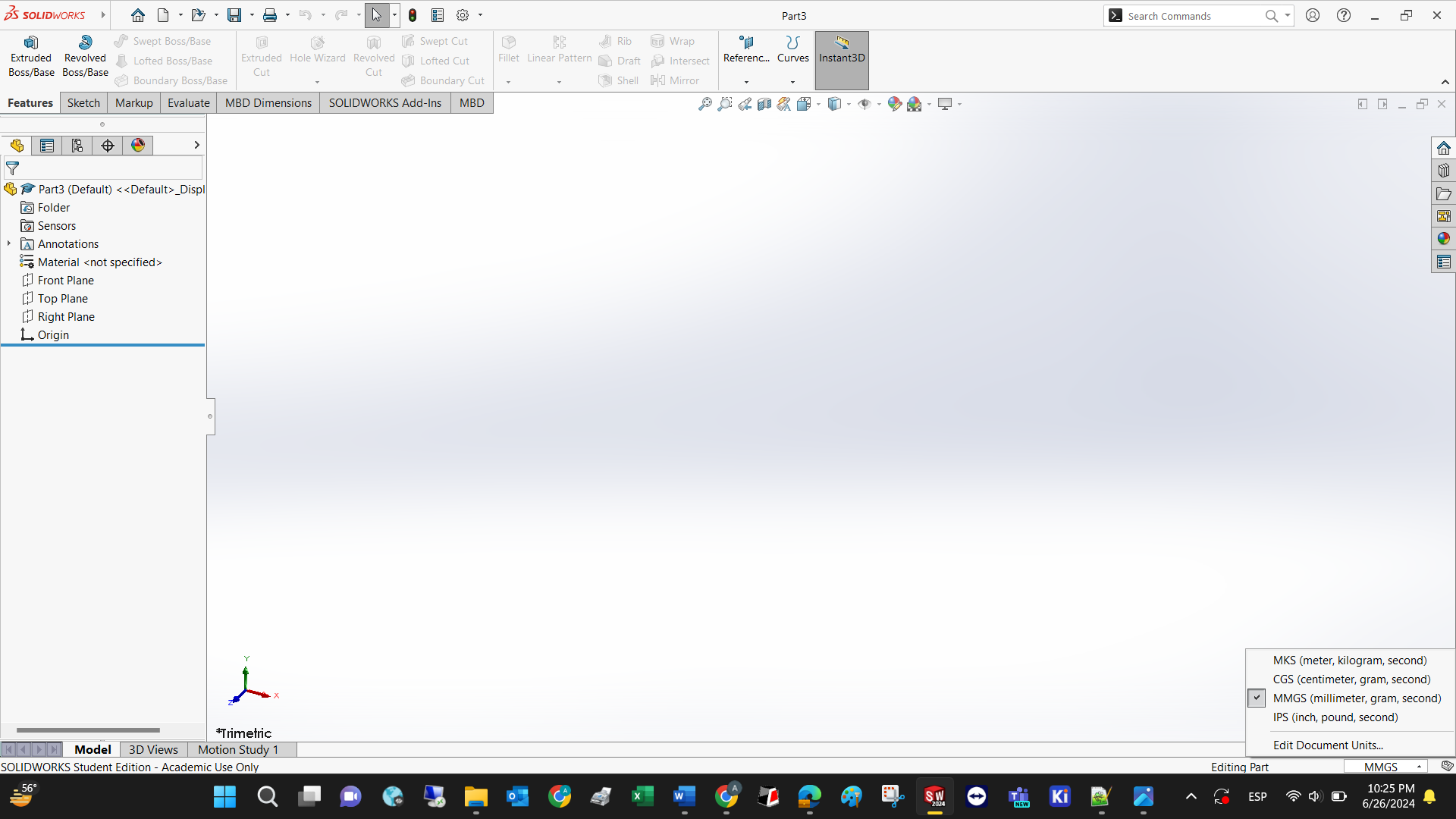
Create a new part (CTRL + N)
Define the measurement units to be used by clicking in the lower left corner of the screen.
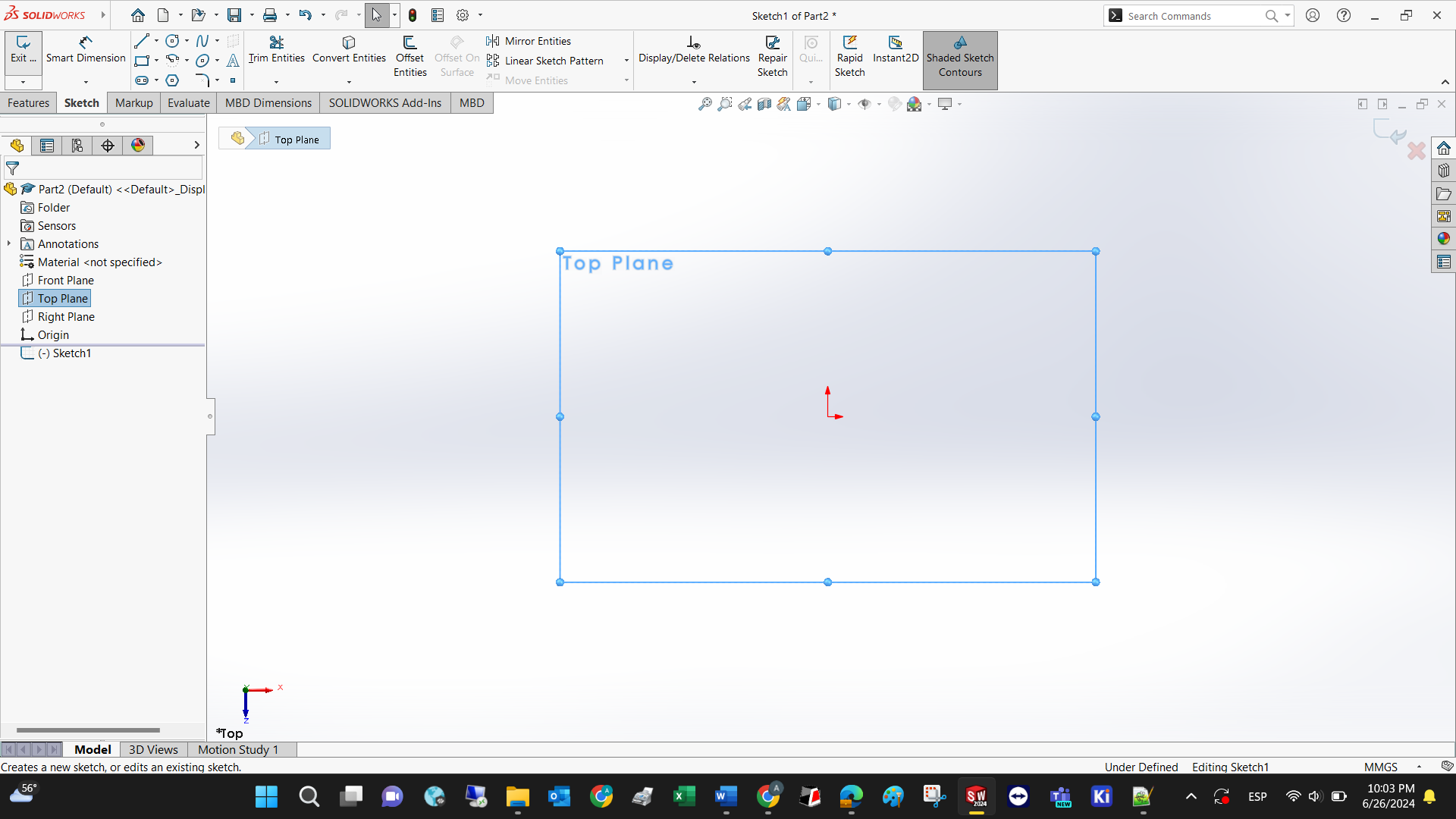
Select the plane you want to work with (the convention is to select the Top Plane)
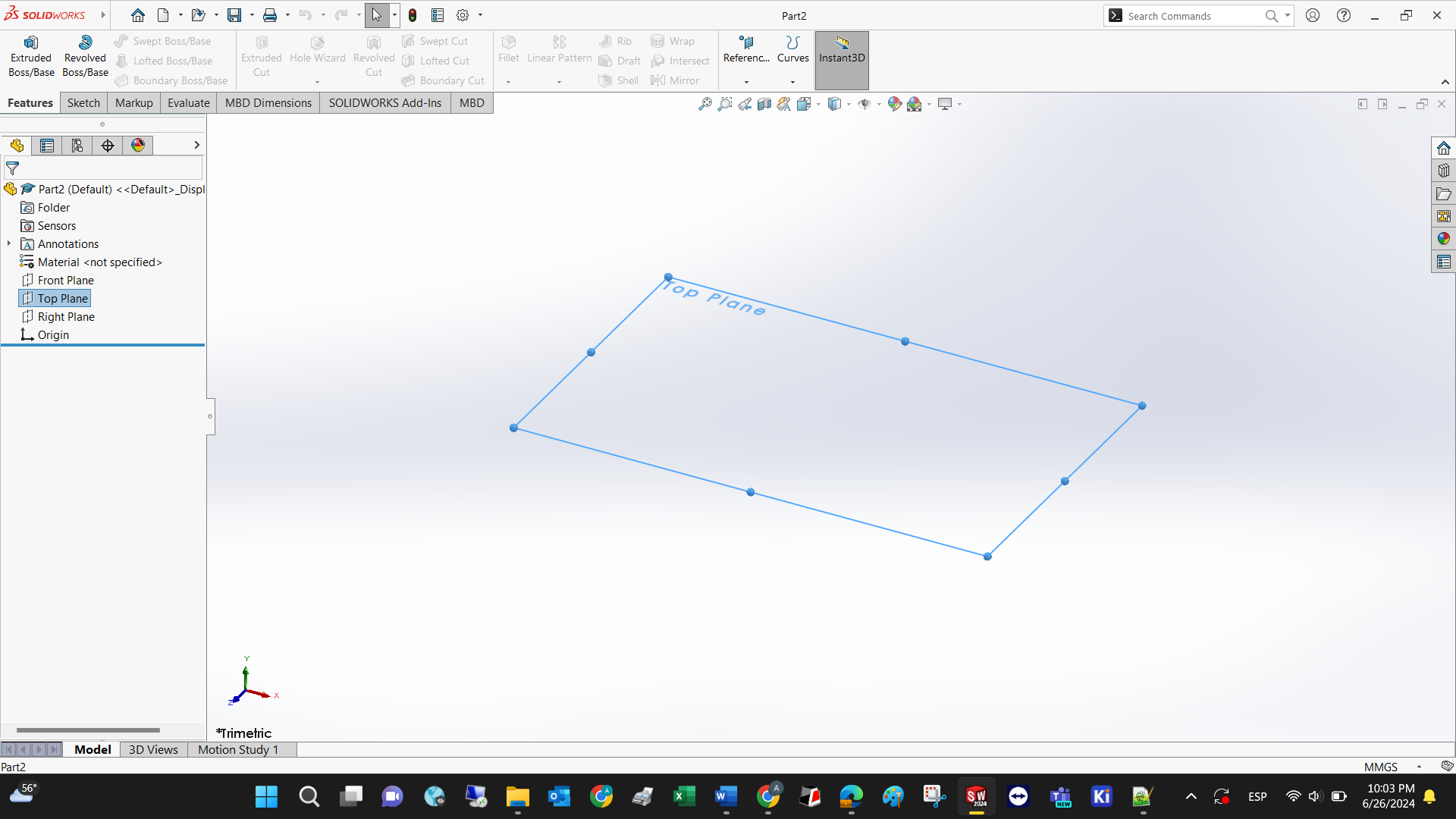
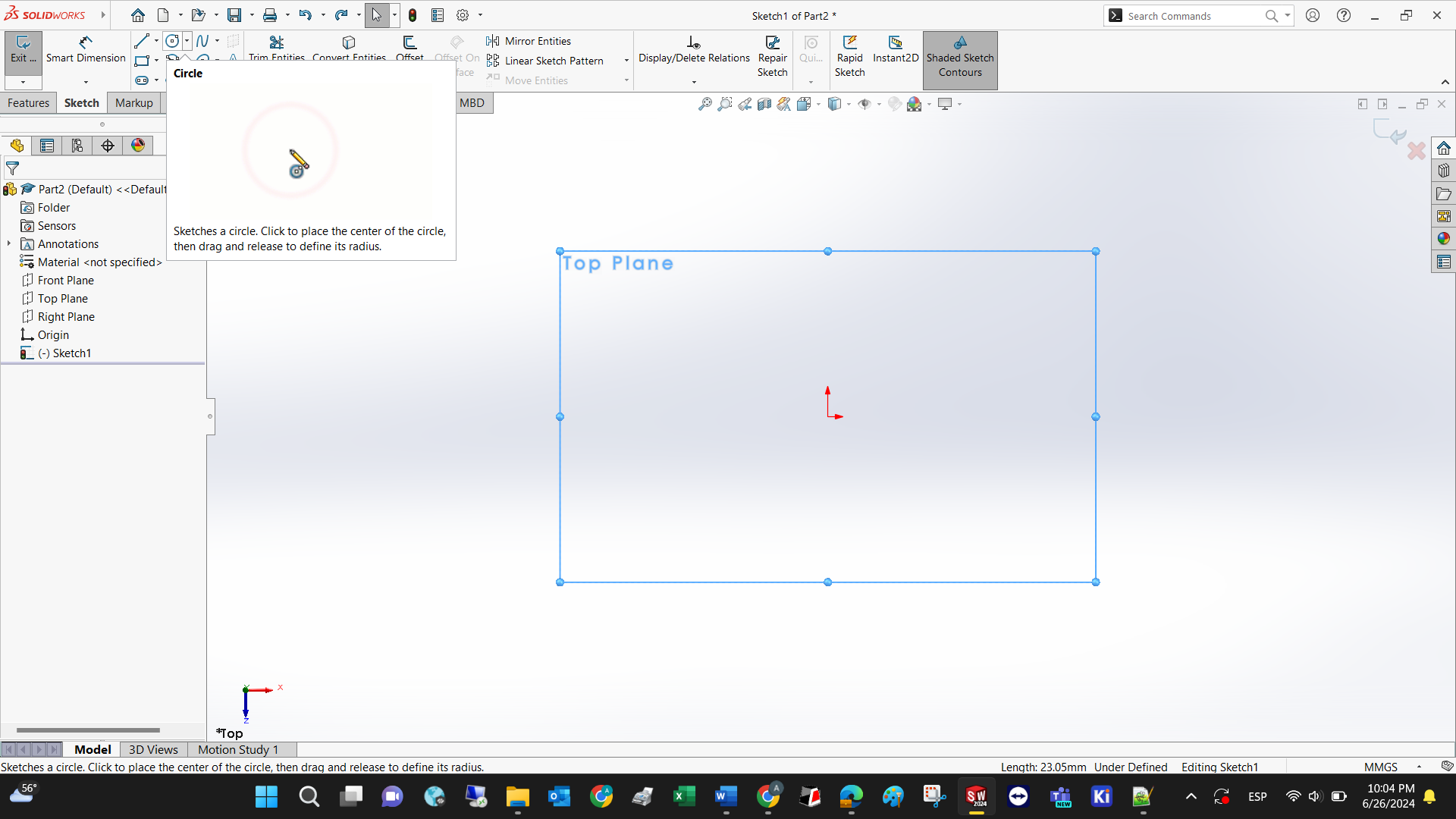
Make a sketch (2D drawing) in the selected plane by using some of the available tools. Feel free to explore each one of them.
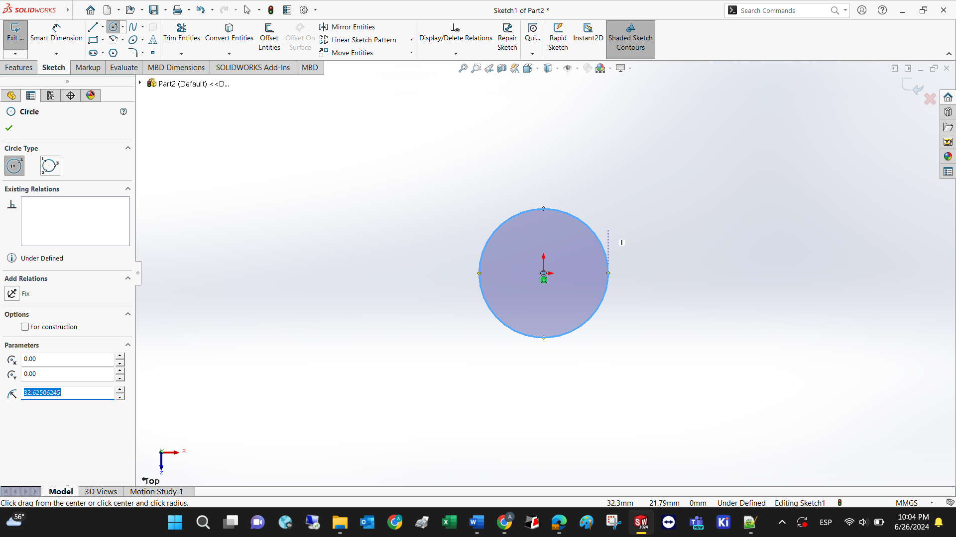
The circle shall be selected; the software shows an animation of how to use it.
For every simple geometric tool, you can define the size of each component.
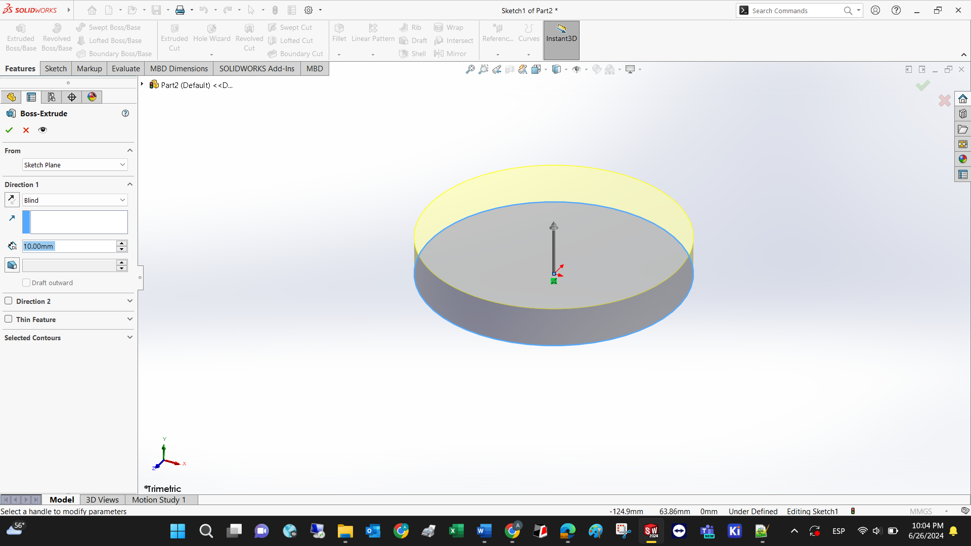
Access the extrude feature under the X commands.
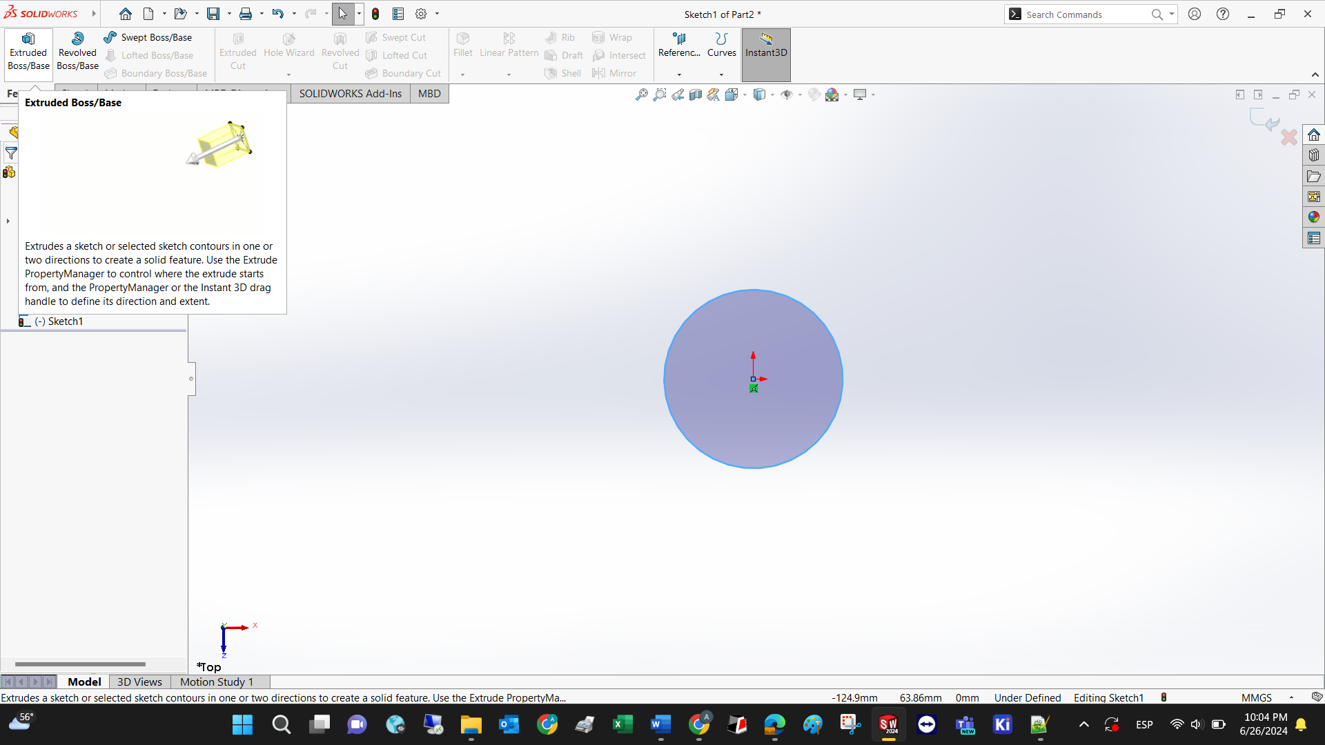
Declare the extrude dimension before clicking the check symbol.
A fillet is used to give roundness to sharp edges, and this feature can only be applied at the intersection of planes, or edges.
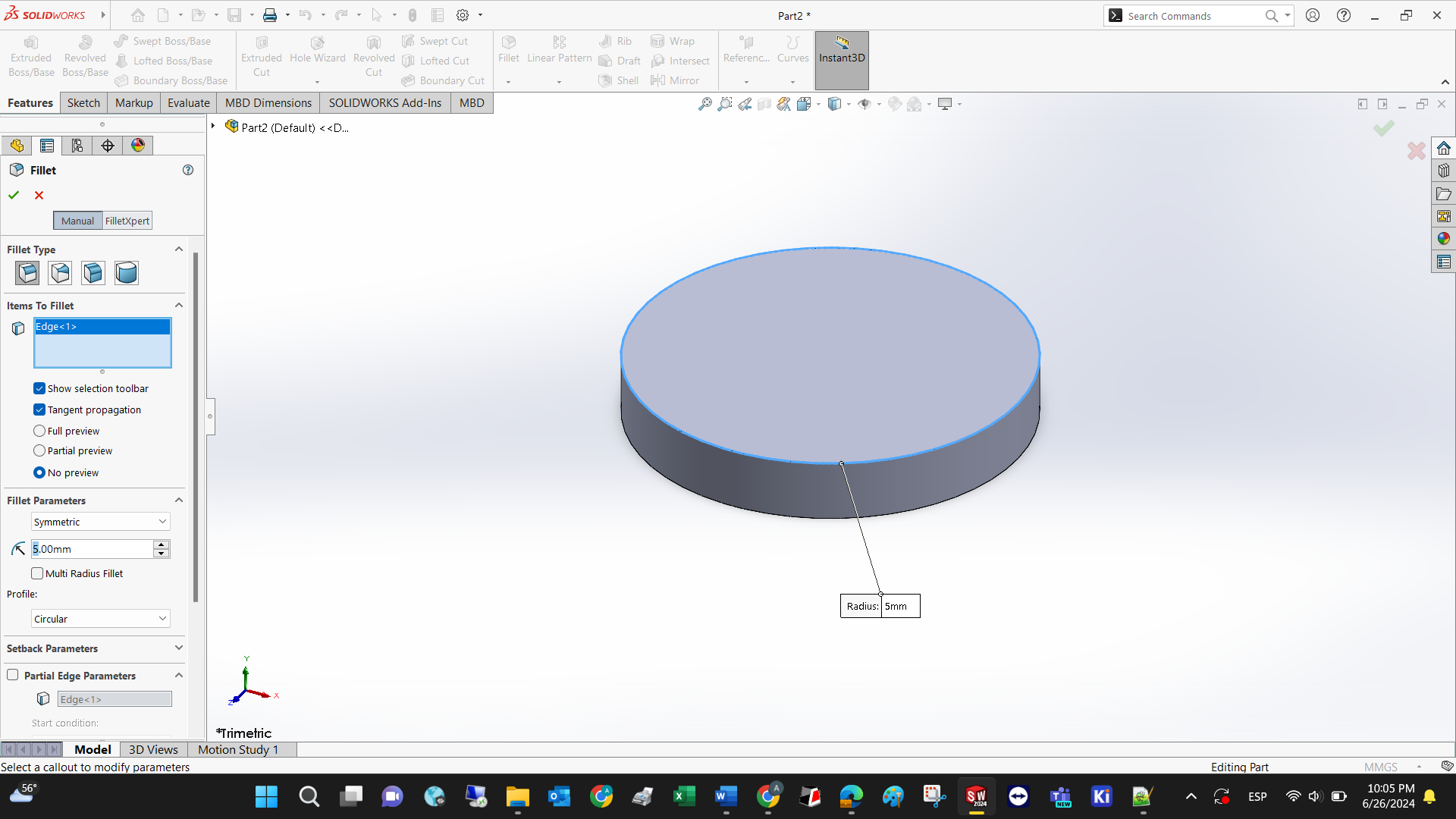
The fillet itself precise a dimension for the fillet radius.
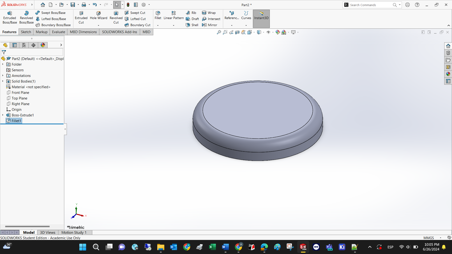
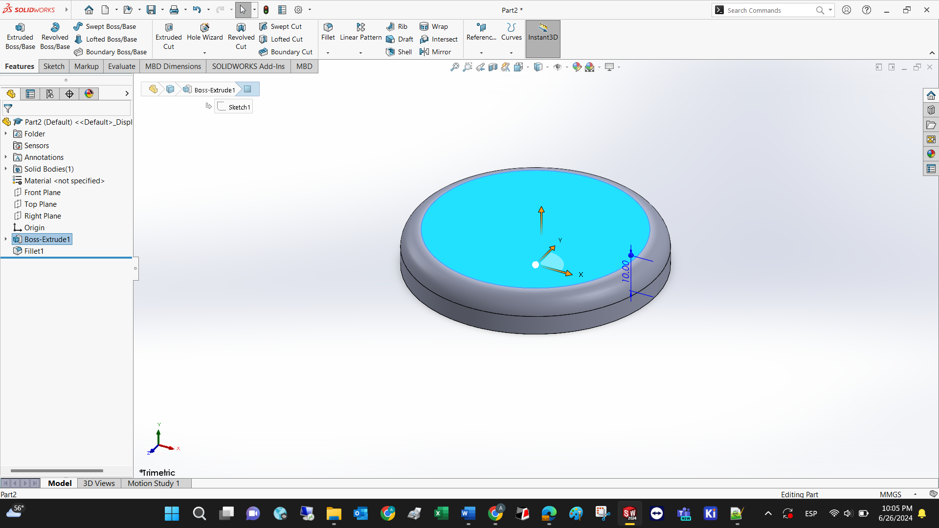
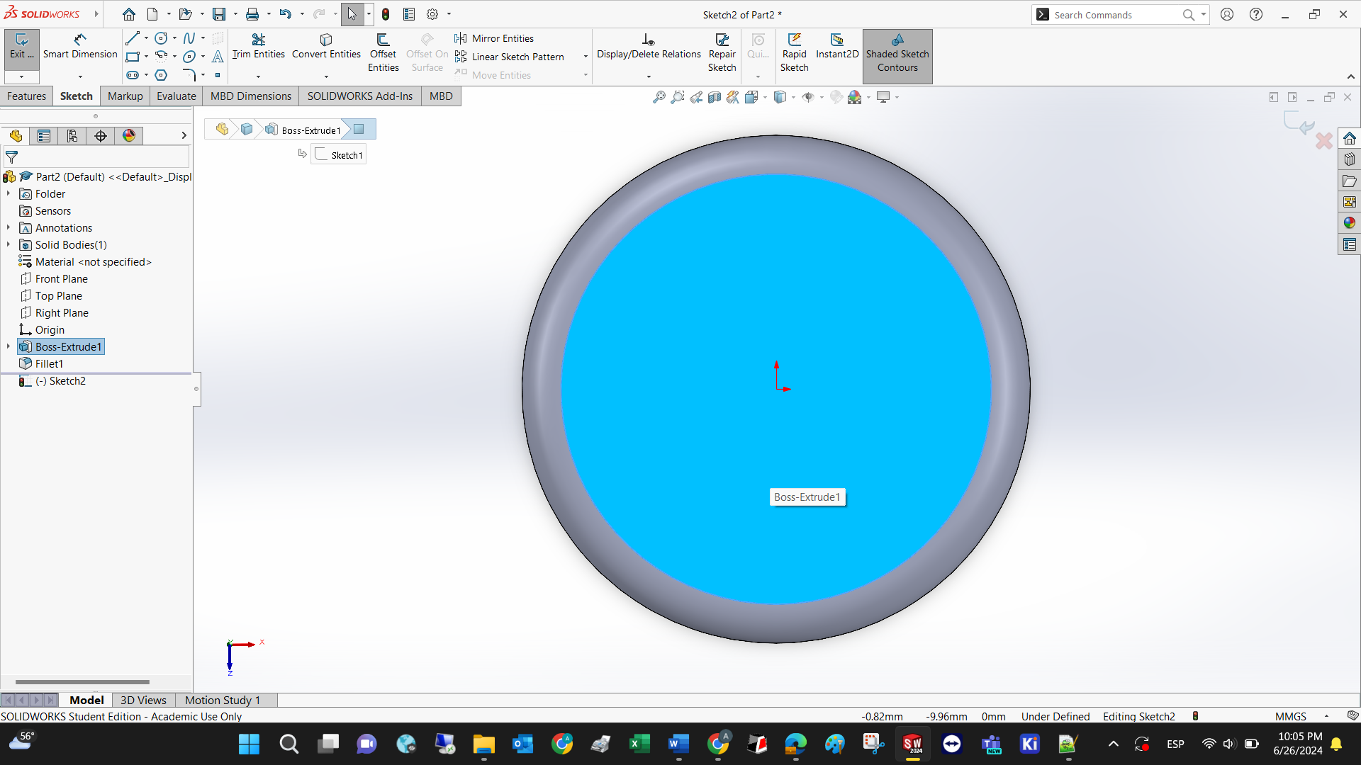
Every flat surface may serve as a new plane to create further 2D and 3D operations. You just need to select it and then state that you want to draw on it.
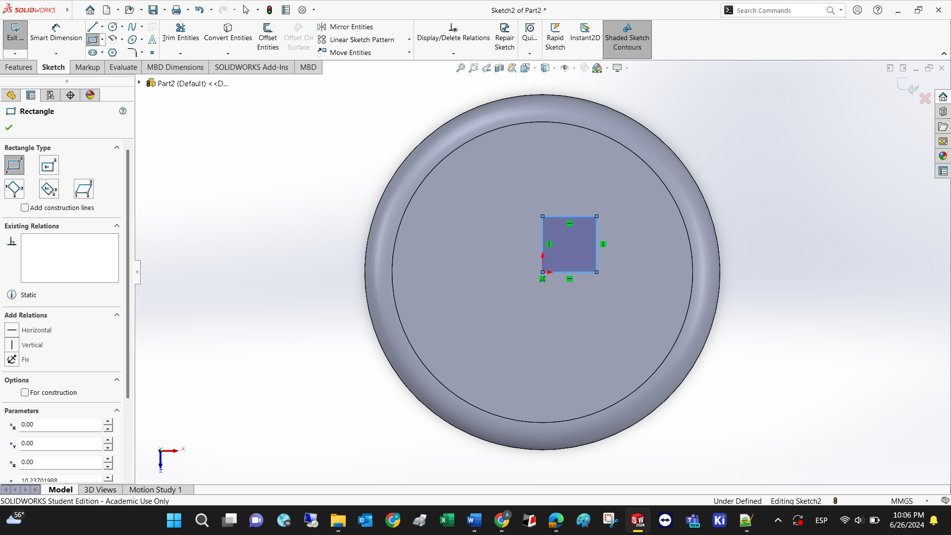
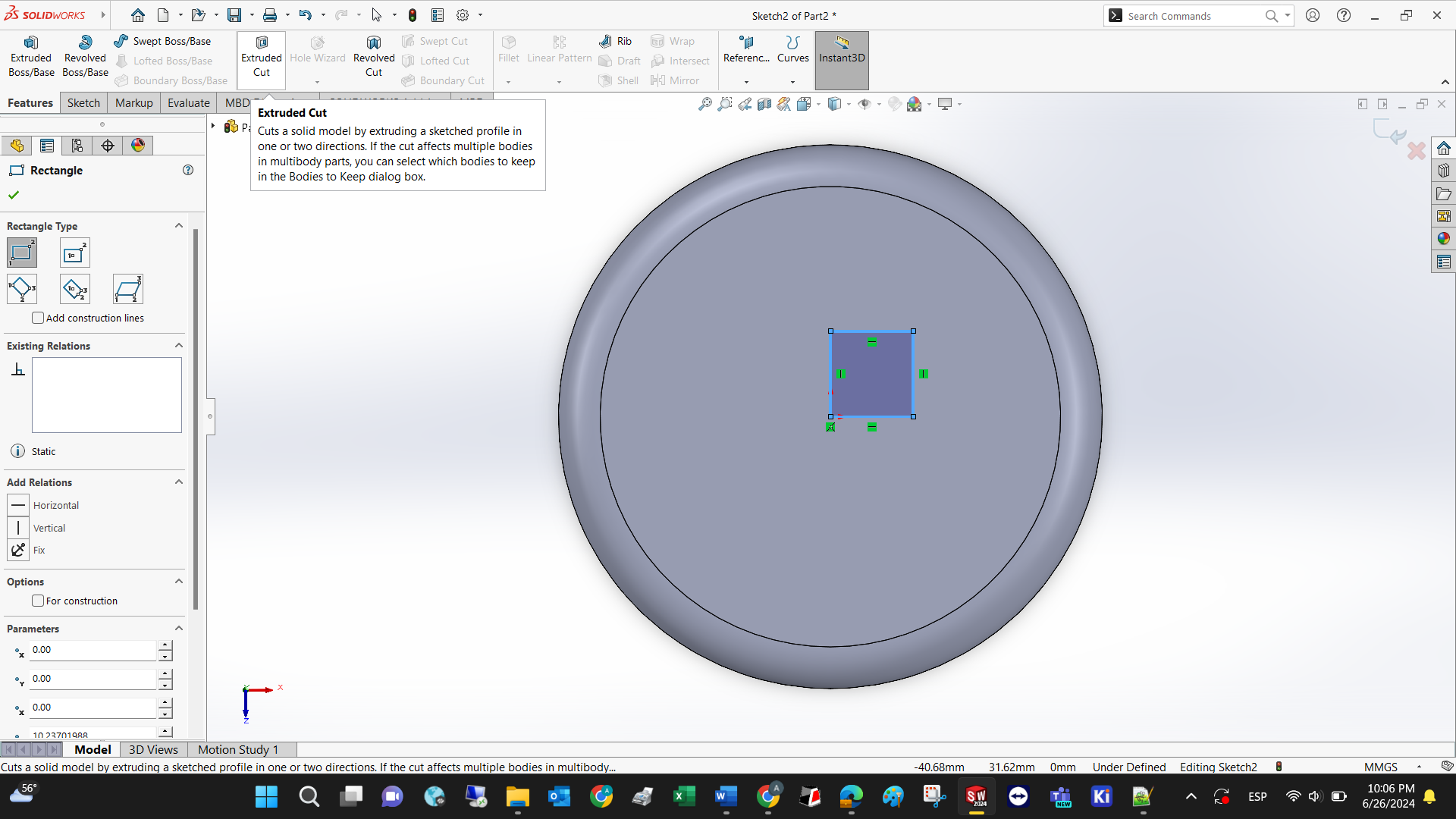
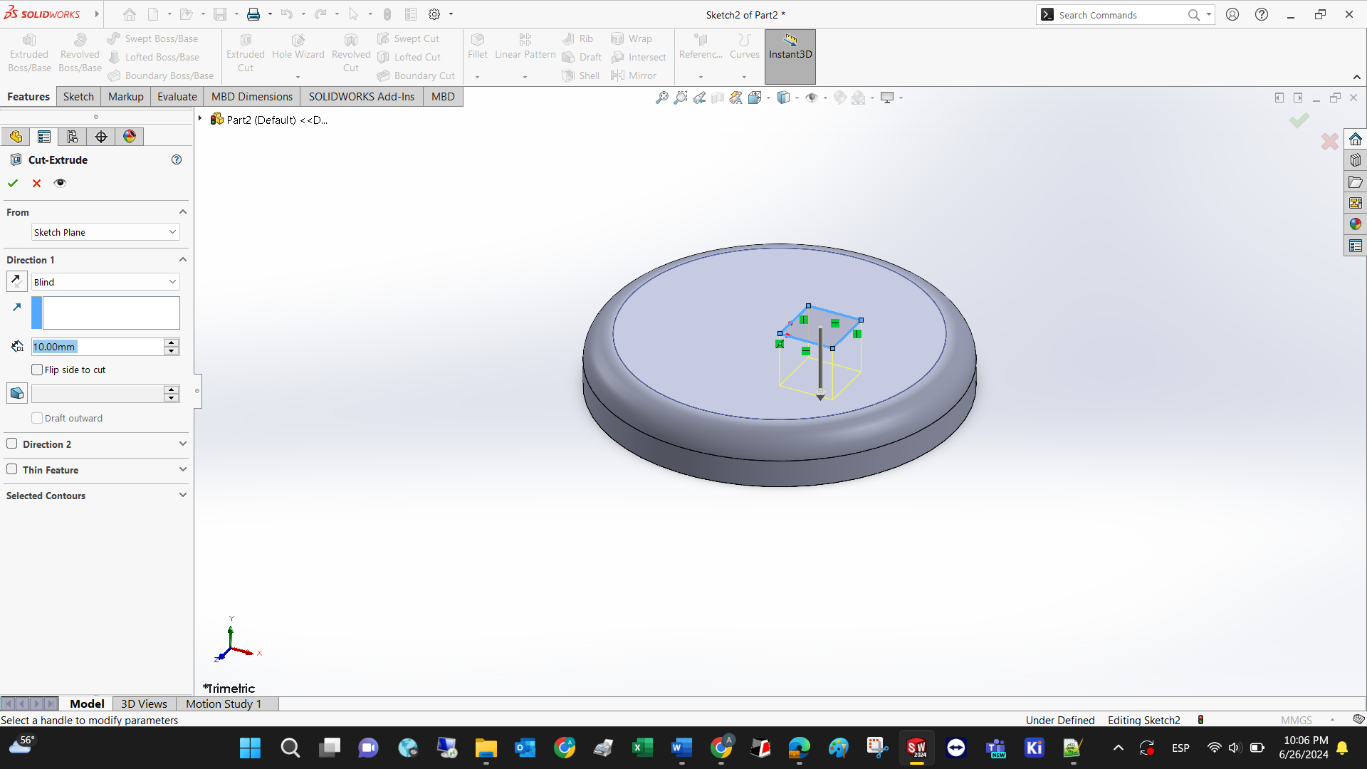
To demonstrate the properties of the extruded cut, lets draw a square first. Select extruded cut under Y.
Set the cut depth
Voila! A new skill has been unlocked. Lets design our possible final project

Step 1: Create a new part: hover your mouse over the SolidWorks logo/file/new or (CTRL+N) then select part.

Step 2: The left part of the software is called Design tree. Select the Top plane and start a new sketch by clicking on Sketch.
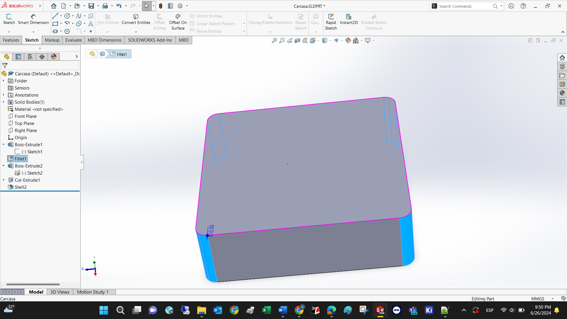
Step 3: Select the top plane and extrude the square. Use the fillet feature to make the sharp edges rounded

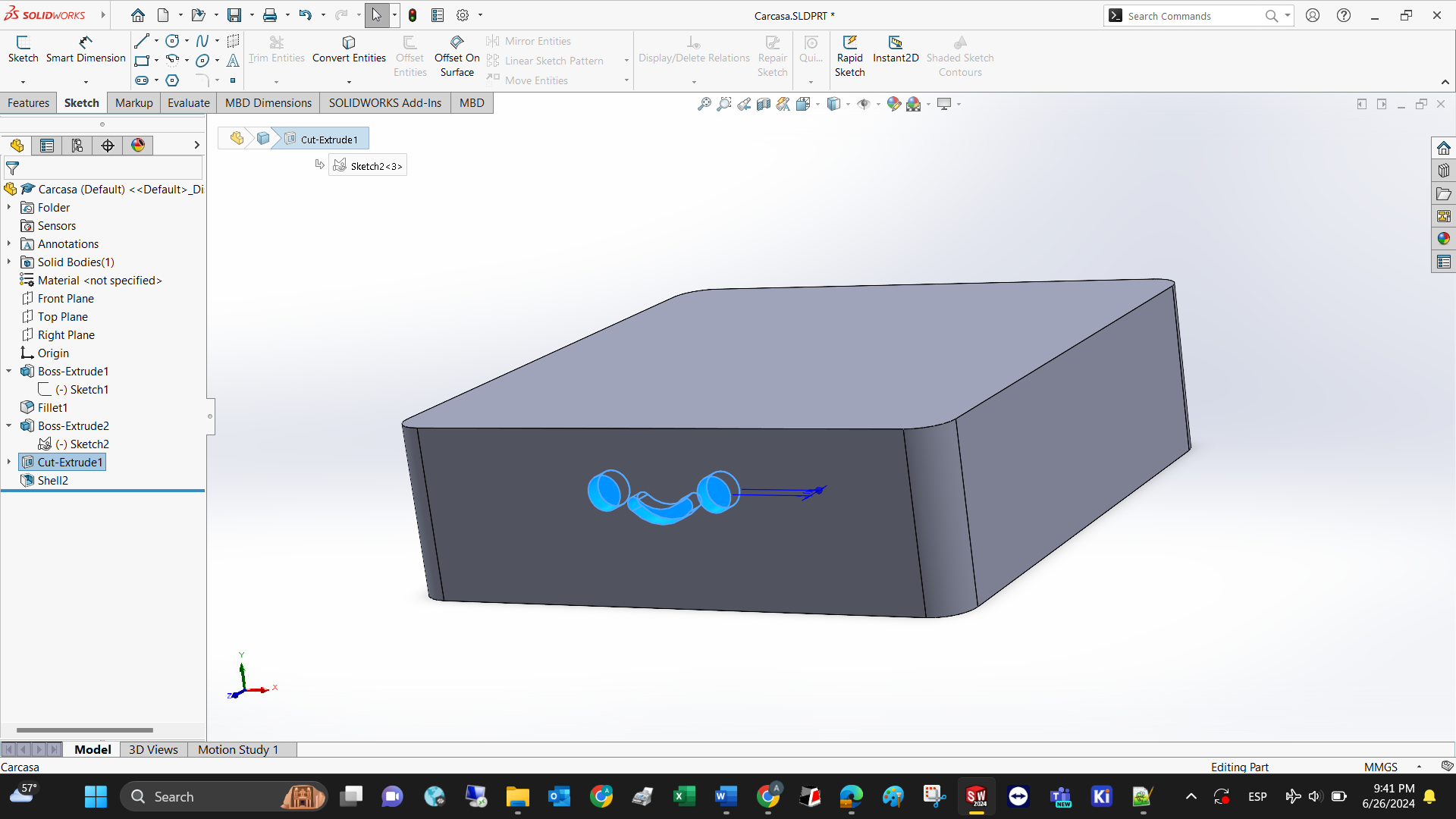
Step 4: Draw the smiley face using circules, arcs, and the trimming feature to cut curves.

Step 5: Extrude cut the face to make it hollow.
Step 6: Shell the model so it can be 3D printed in less time.
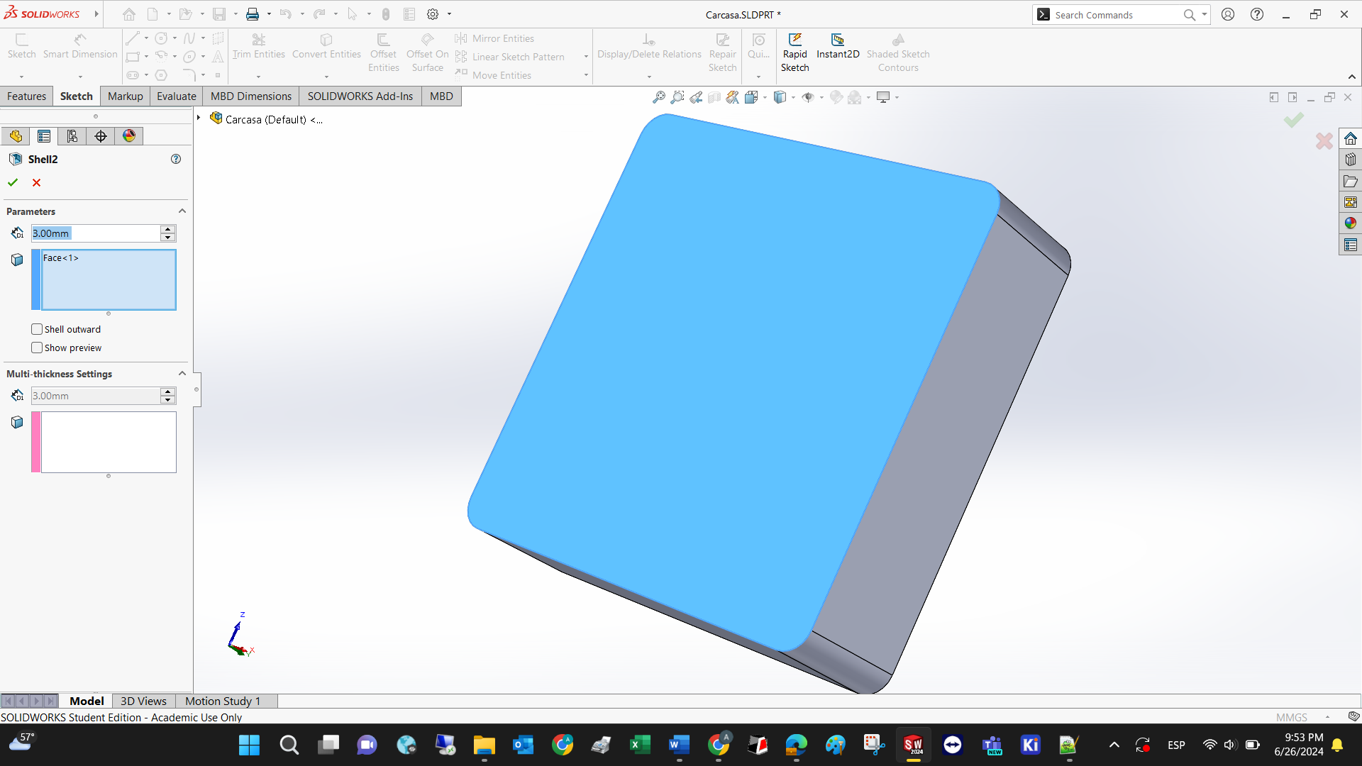
Voila! This is the conceptual design of the final project.