11. Input Devices
I will learn to use input devices such as sensors this week and will use them for my final project.GROUP PAGE
Input devices are components that send data to the microcontroller for processing, allowing it to perform the corresponding actions. These devices are essential in various applications as they provide the necessary information for the system to make decisions and respond to different stimuli. By converting physical quantities into electrical signals, input devices enable the microcontroller to interact with the external environment and execute programmed tasks based on the received inputs.
- Buttons and Switches: Allow the user to input simple commands, such as turning an LED on or off, starting or stopping a motor, etc.
- Temperature Sensors: Measure ambient temperature and send the data to the Arduino for monitoring or controlling heating/cooling systems.
- Potentiometers: Variable devices that allow adjusting analog values, such as the brightness of an LED.
- Light Sensors (LDR): Detect the intensity of ambient light and enable the Arduino to react accordingly, such as turning on lights in the dark.
- Microphones: Capture sound and allow the Arduino to respond to audio signals, like turning on a light in response to a clap.
- Proximity or Infrared Sensors: Detect the presence of nearby objects and can be used to trigger actions when movement is detected.
- Accelerometers and Gyroscopes: Measure acceleration and orientation, respectively, and are used in projects that require detecting movement or tilt.
- Humidity and Soil Sensors: Measure ambient or soil moisture and are used in environmental monitoring or gardening projects.
- Joysticks: Provide multidirectional analog control, useful in robotics and gaming projects.
- Gas Sensors: Detect the presence of specific gases and are used in environmental monitoring and safety projects.
For my project
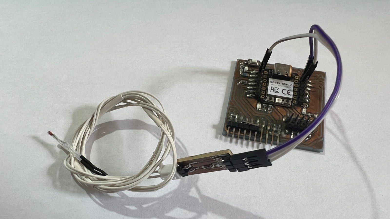
For my project, I will use two sensors: one that will measure the temperature and maintain control for my ceramic heaters. The sensors and heaters will be in a closed system controlled by a PID. To control the speed of the motors when collecting the filament, I will use a slot sensor.
temperature sensor
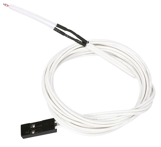
NTC Thermistor 100k,an NTC (Negative Temperature Coefficient) thermistor of 100k is a type of resistor whose resistance decreases as the temperature increases. The "100k" indicates that the nominal resistance value of the thermistor is 100,000 ohms at a specific temperature, usually 25 degrees Celsius. This type of thermistor is commonly used in temperature measurement and control applications due to its high sensitivity to temperature changes.

Key Features:
- Negative Temperature Coefficient (NTC): This means its resistance decreases as the temperature increases.
- High Precision: NTC thermistors are very precise in measuring small temperature variations.
- Applications: They are used in digital thermometers, temperature control systems of household appliances, and electronic circuits where temperature monitoring and regulation are necessary.
Example of Use:
In a 3D printer, a 100k NTC thermistor can be installed in the print head (hotend) to measure the temperature and ensure it stays within the optimal range for melting the printing filament correctly. This ensures that the filament melts and flows properly, providing accurate and high-quality prints.
connection diagram
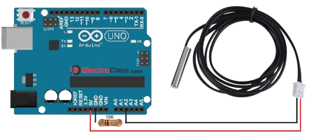
One terminal of the thermistor is connected to the analog pin A0, and the other terminal is connected to the 5V pin. Additionally, there is a 10k ohm resistor connected between the analog pin A0 and the GND pin of the Arduino Uno board.
pcb design
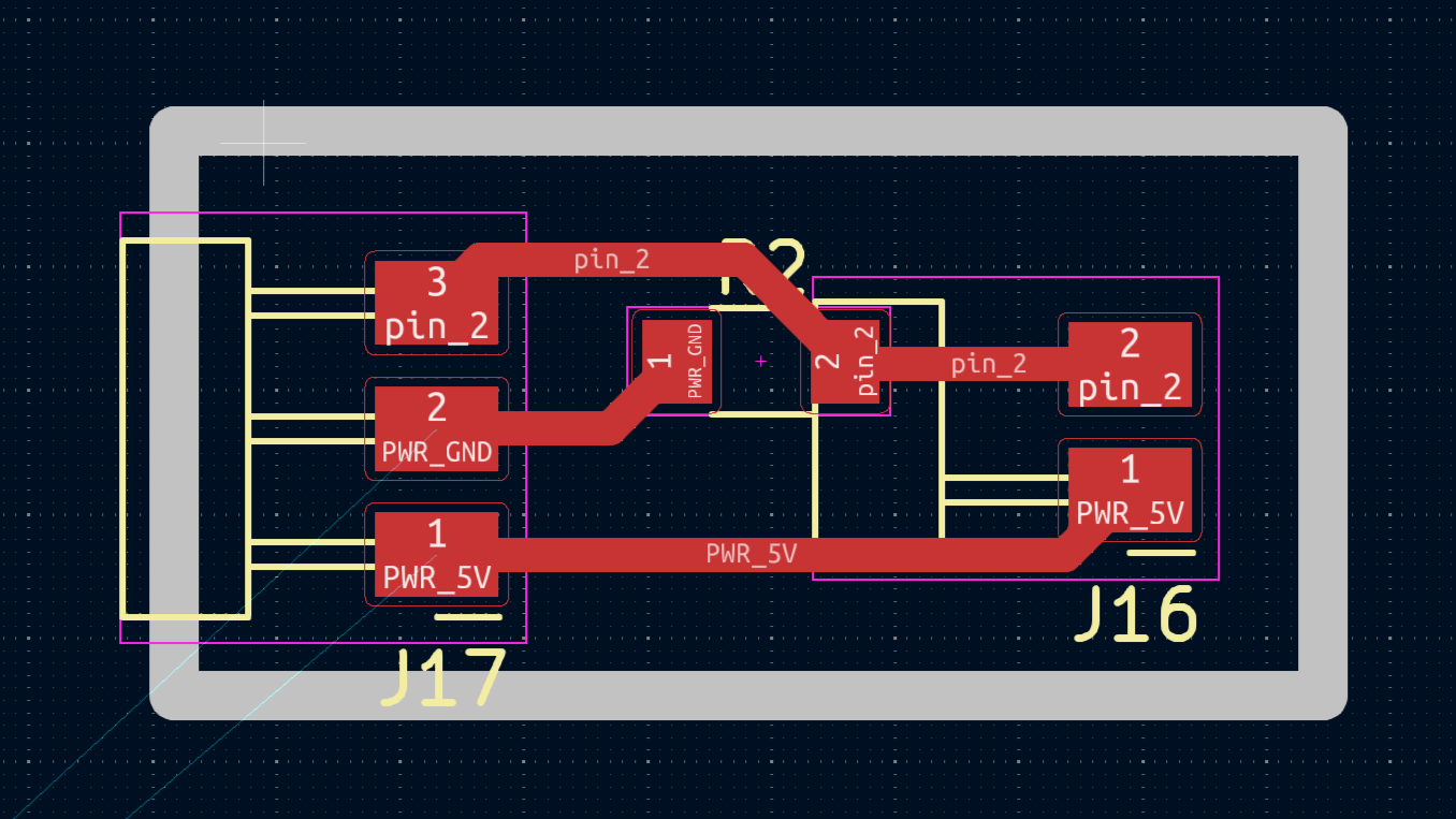
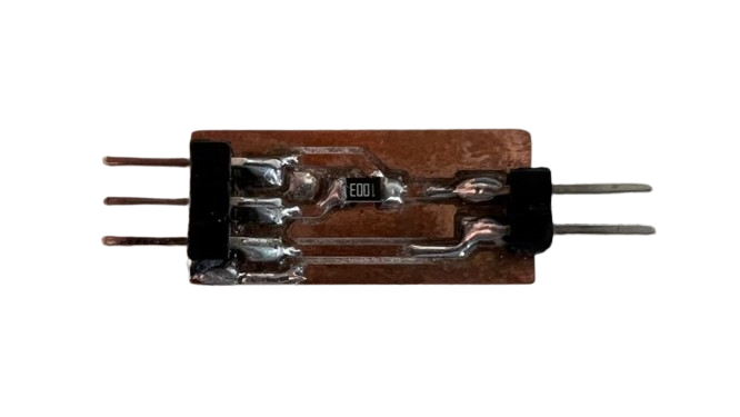
Next, you can see the schematic diagram and the final shape of the fabricated board for the temperature sensor. It is not very complex since it only requires pins for connections and a ground resistor.

pcb manufacture
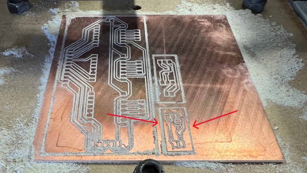
Here you can see the cut and then soldered board. This board was cut along with other boards from other weeks. The board is really small and not very complex. To learn how it was cut, visit the page for week 4.
code
This Arduino code measures the temperature using a 100k ohm NTC thermistor. It initializes constants and variables for the thermistor and a fixed 100k ohm resistor, along with the Steinhart-Hart coefficients necessary for converting resistance to temperature. In the setup(), serial communication is configured. In the loop(), the code reads the analog value from the thermistor on pin A0, converts it to voltage, and then calculates the thermistor's resistance using the voltage divider formula. The resistance is converted to temperature in degrees Celsius using the Steinhart-Hart equation, and the result is printed to the serial monitor. This cycle repeats every second to update the temperature readings.code
result
With a quick demonstration and a match, you can see how the sensor measures the temperature.
slot sensor
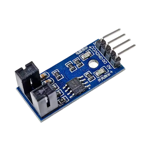
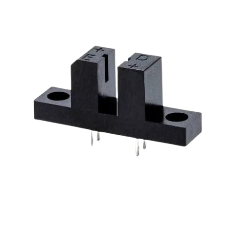
A slot sensor, also known as an "optical slot sensor" or "slot-type sensor," is an optical sensor used to detect the presence or absence of an object passing through a slot in the sensor. These sensors operate by interrupting a beam of light that traverses the slot.
Components and Functioning:
- Light Emitter: Typically an infrared or visible LED that emits a beam of light.
- Light Receiver: A photodetector, such as a phototransistor or photodiode, that detects the light emitted by the LED.
- Slot: The gap between the emitter and receiver through which the object to be detected passes.
When an opaque object passes through the slot, it blocks the light beam between the emitter and receiver, causing a change in the signal from the receiver. This change can be interpreted by a control circuit to perform various actions, such as counting objects, measuring speed, or detecting positions.
Common Applications:
- Object Counters: Used in production lines to count products passing through.
- Rotation Detectors: Used in optical encoders to measure the speed and position of moving parts.
- Security Systems: Used to detect the opening or closing of doors or barriers.
connection diagram
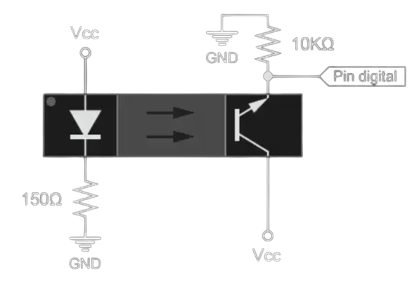
The diagram shows the connection of an optical slot sensor. The light emitter (LED) is connected to Vcc through a 150-ohm resistor and to ground (GND). The receiver (phototransistor) has its collector connected to Vcc and its emitter connected to a digital pin of the microcontroller through a 10k ohm resistor, which is also connected to ground (GND). When the LED's light reaches the phototransistor, the digital pin registers a low state. If an object blocks the light, the digital pin registers a high state due to the 10k ohm pull-up resistor.
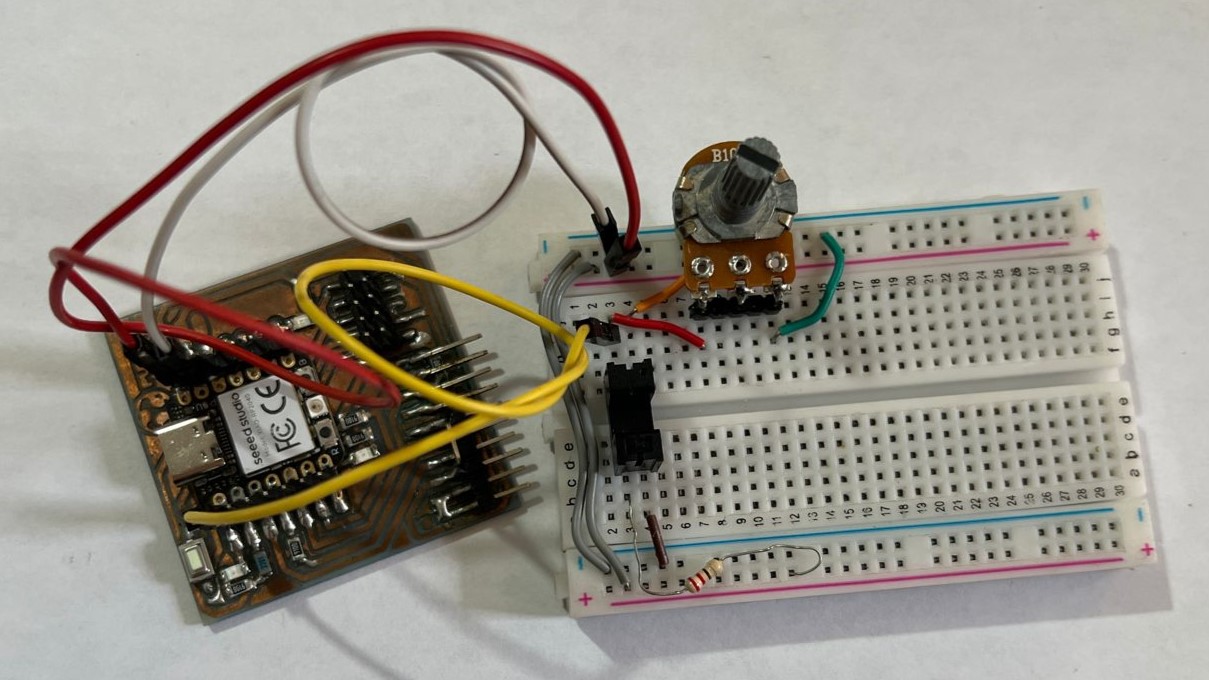
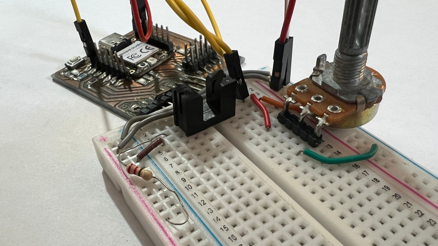
breadboard connection
Next, you can see the connections I used to test this sensor. I used a potentiometer to achieve a resistance of 10K.
code
This code is designed to read the value from a photoresistor connected to an Arduino Uno and calculate its resistance using a voltage divider. The setup initializes serial communication at a baud rate of 9600. In the main loop, the code reads the analog value from the photoresistor pin (A0), converts this value to a corresponding voltage, and then calculates the resistance of the photoresistor using the known value of a fixed resistor (10k ohms) in the voltage divider circuit. The calculated resistance, along with the raw sensor value and the voltage, is printed to the serial monitor. The loop runs continuously with a one-second delay between readings.code
result
Here you can see how, using a torn sheet of paper with different opacities, we can obtain a fairly precise sensor that emits a higher or lower voltage depending on the thickness of the paper.