7. Computer-Controlled Machining
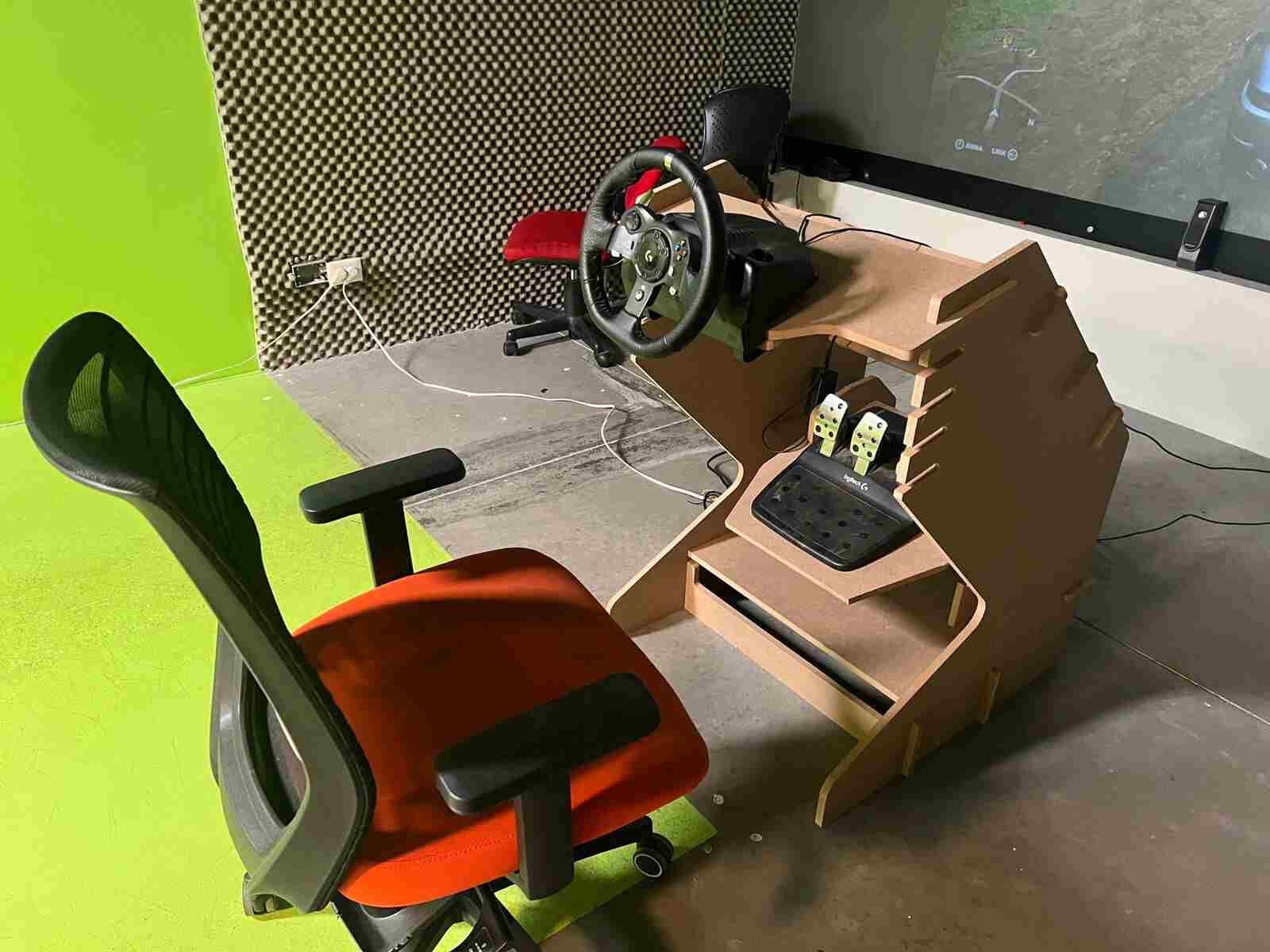
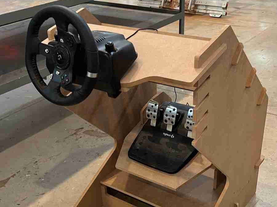
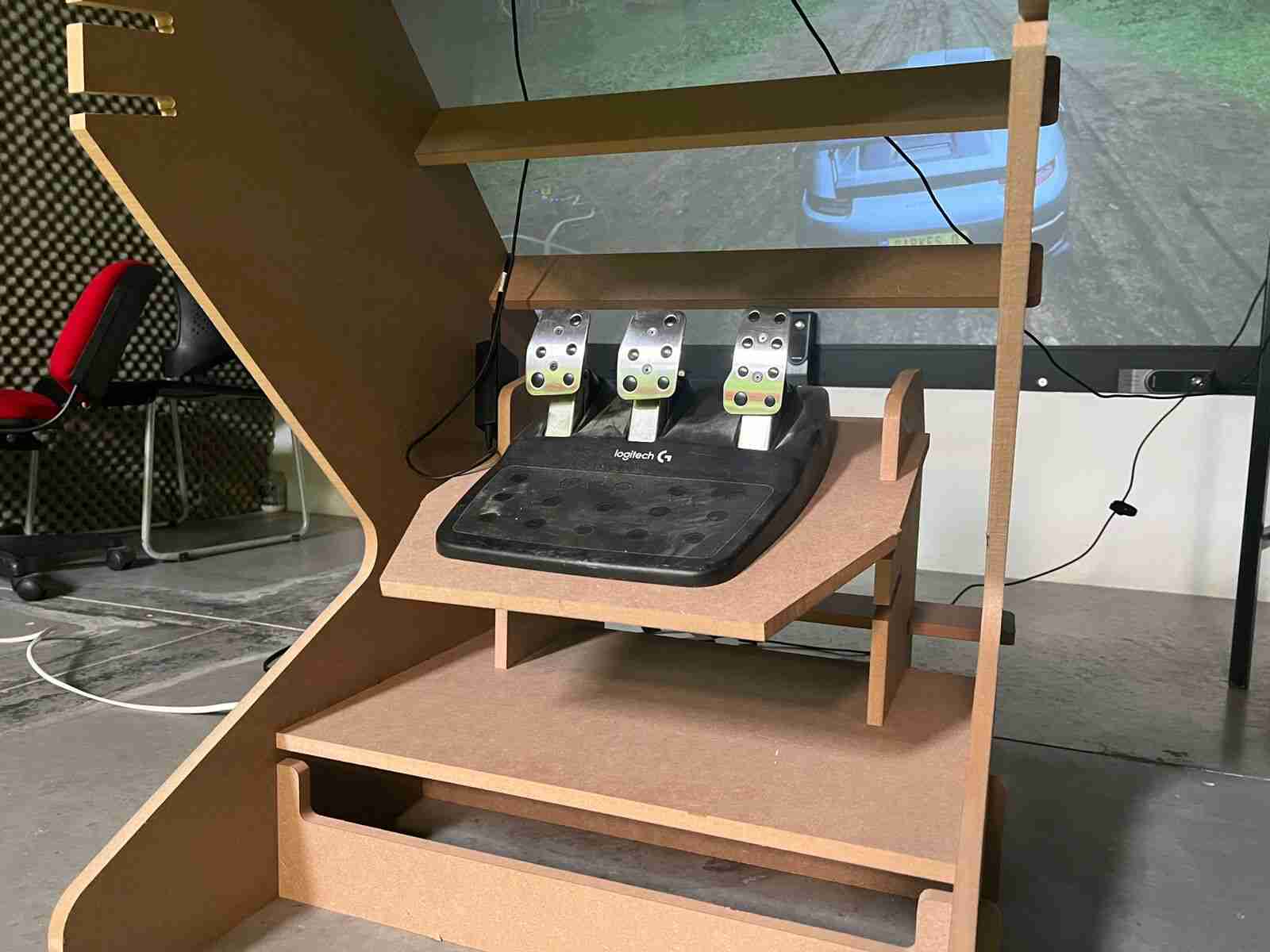
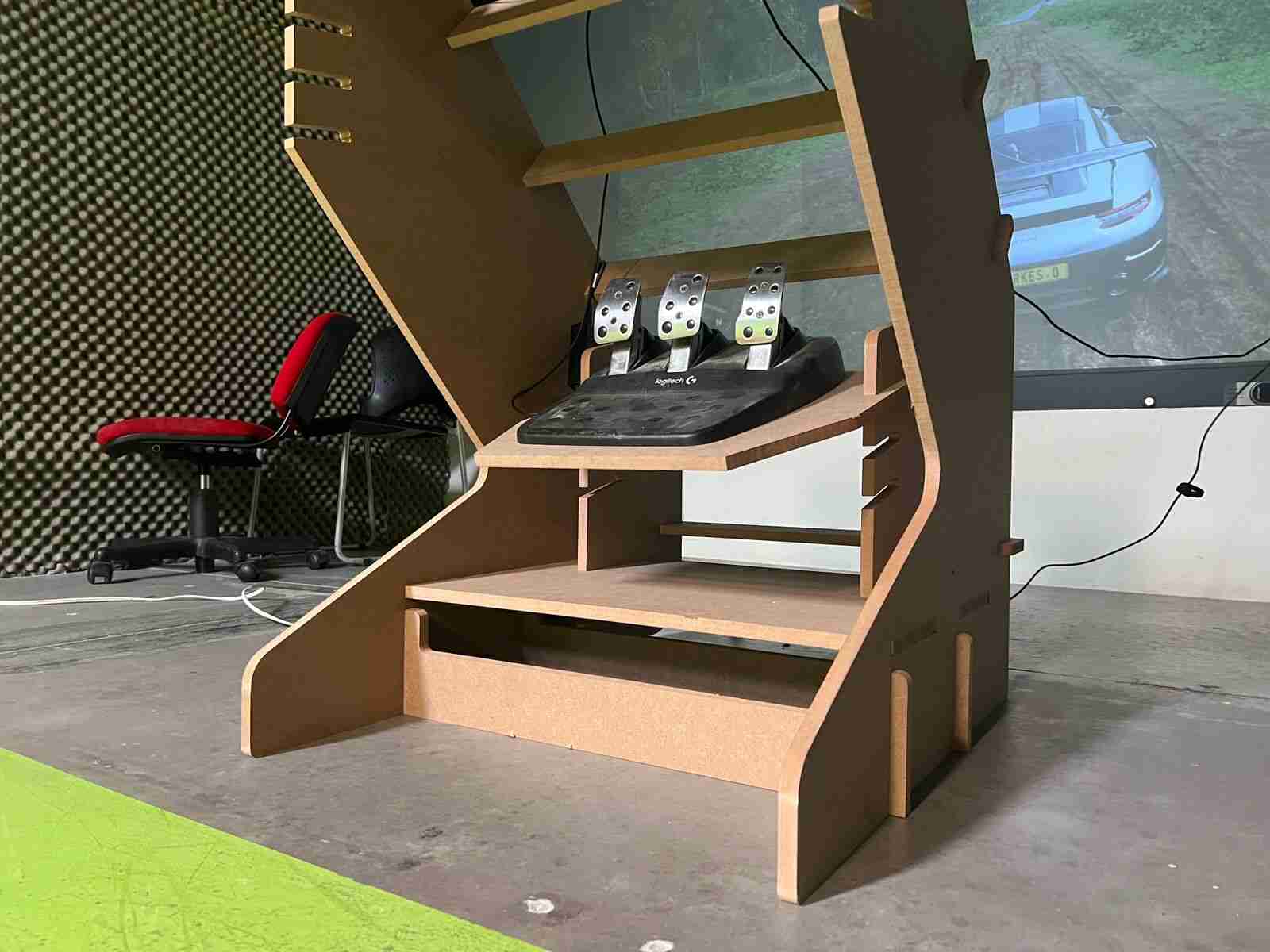
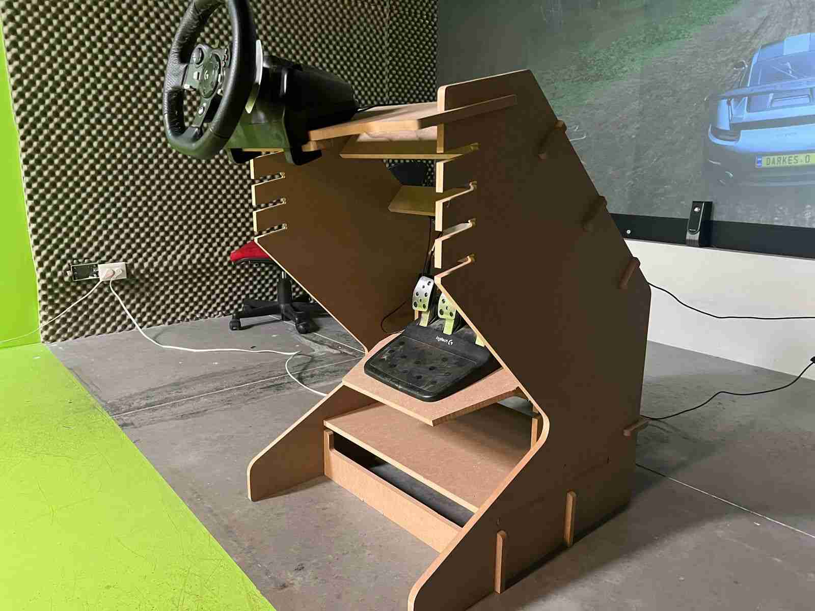
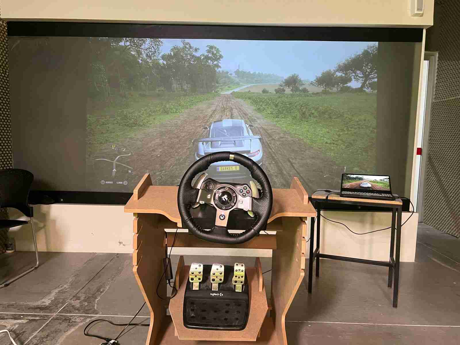
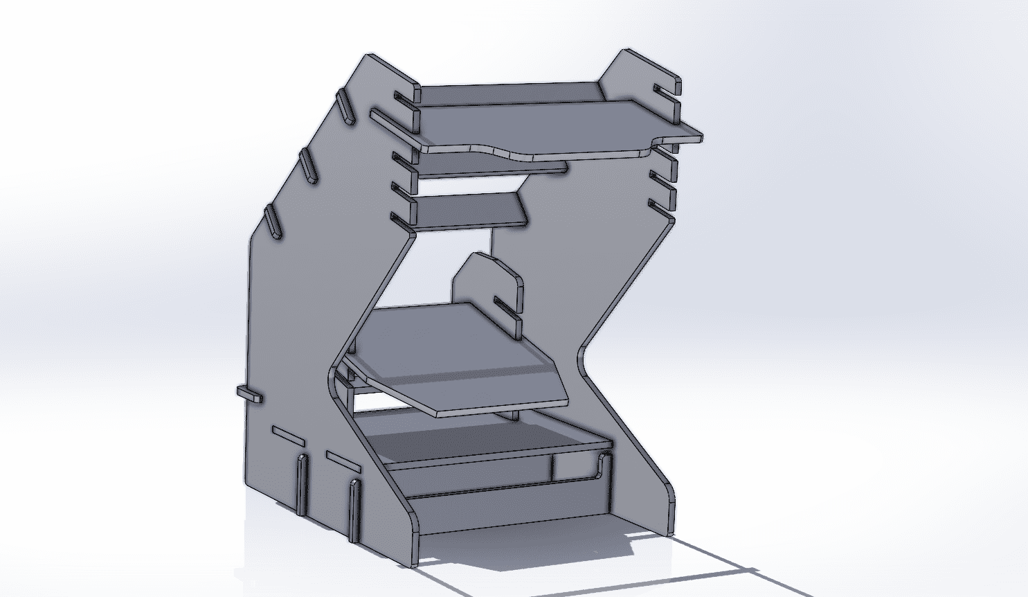
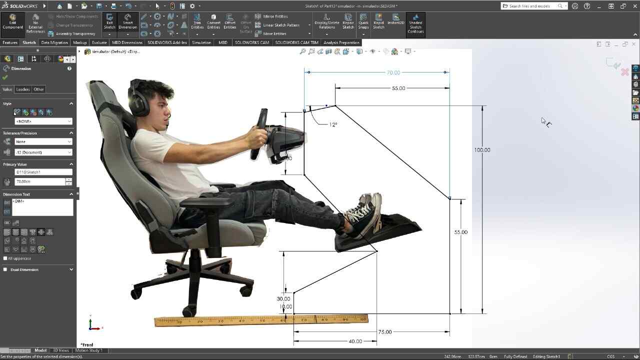
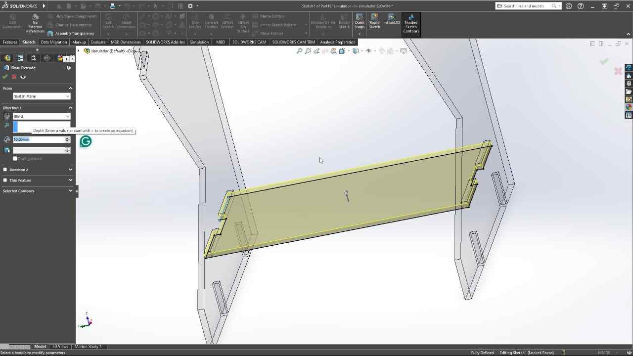
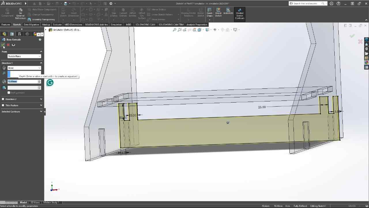
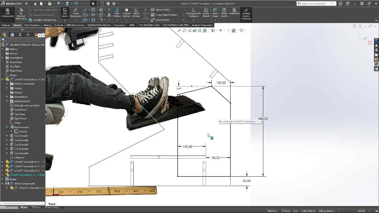
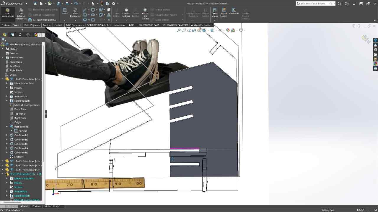
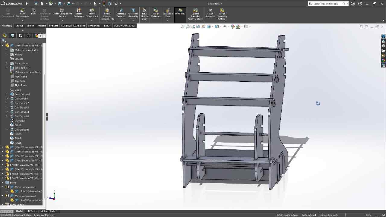
This week we were asked to design, mill and assemble a relatively large model with a CNC machine, in this case, we were using a CNC router and for the manufacturing material, 15 mm MDF.For this practice, I decided to make a piece of furniture for my racing simulator, since it is somewhat uncomfortable, using the simulator on a normal desk, this simulator will have different heights and adjustable positions so that it better adapts to the person who is going to use it use.
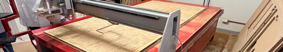
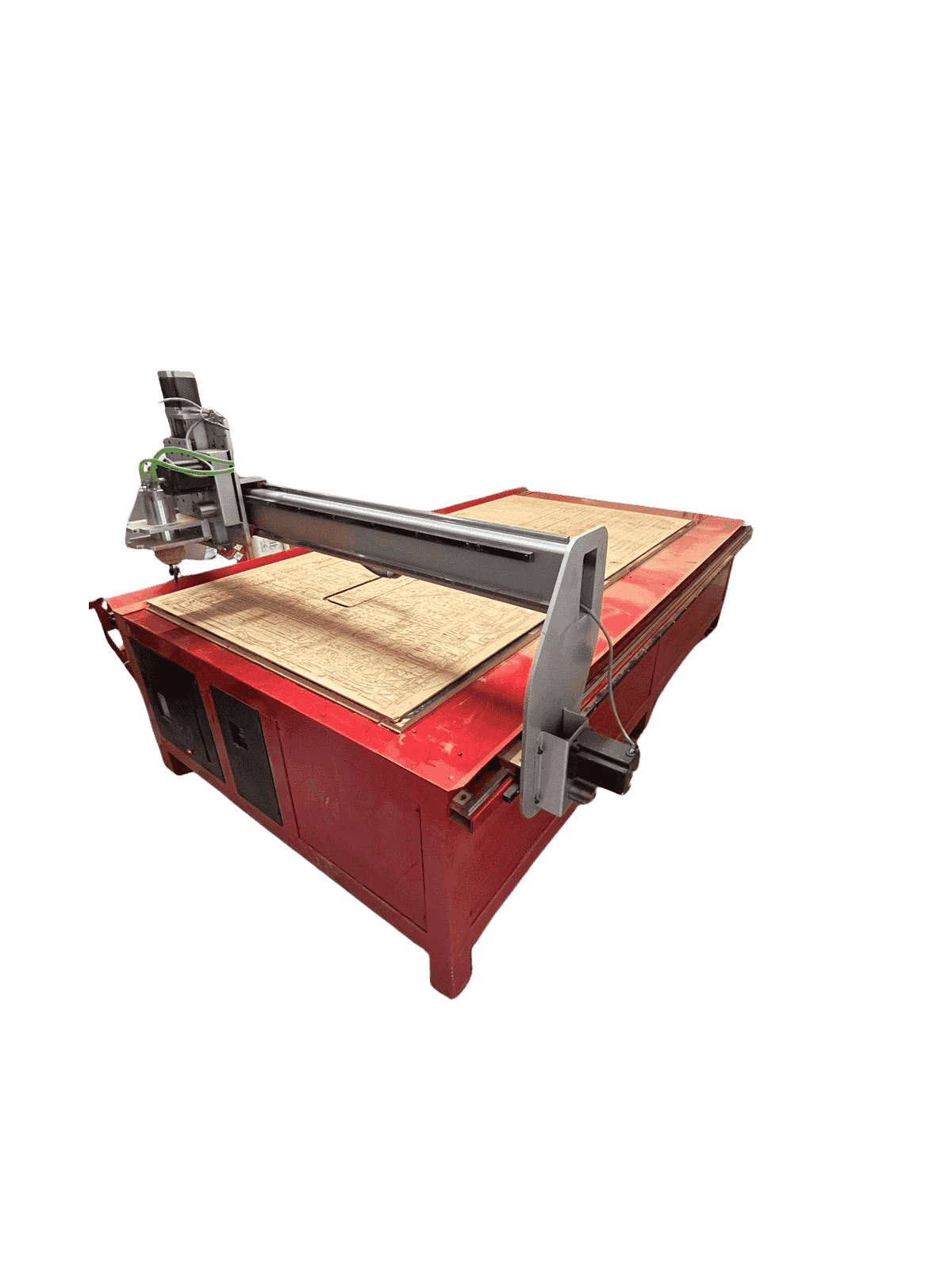
router CNC
A CNC router is a computer numerical control machine used for cutting, carving, milling, and engraving materials such as wood, plastic, and metal. It operates through software that controls a rotating cutter over the work material in three dimensions. It consists of a work table and a milling head that moves according to coordinates predefined by the program. Widely used in manufacturing, woodworking, the furniture industry, and other fields where precision and automation in material processing are needed.
for more information visit the GROUP PAGE
machine
CNC router
- Machine: Generic Made by University
- Model: none
- Motor Power: 4 HP at 24000 rpm's
- Power Supply: 220v/2F/3.5KW
- Dimensions: 3 x 1.8 x 1.7 mts
- Material Fixtures: Nails


.jpg)

Safety equipment
We will use safety equipment to protect ourselves, since the machine rotates at very high revolutions and may cause some fragments of the material to be thrown out. In addition, the material we will be using is MDF and when using the machine it produces a very fine dust that can irritate the throat.

mechanic's coat

security boots
safety glasses

face mask
3D MODEL
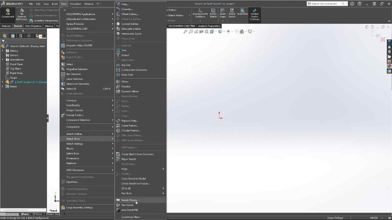


program

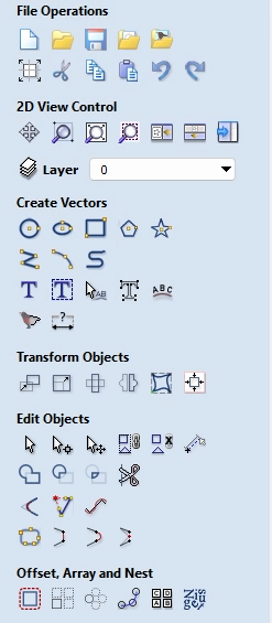
vcarve


tools
.png) |
New file, save, copy, duplicate, open, etc. |
.png) |
These tools allow us to create lines, curves, and texts to generate cuts or edit existing ones. |
.png) |
These tools enable us to move, scale, center, and transform vectors within the file. |
 |
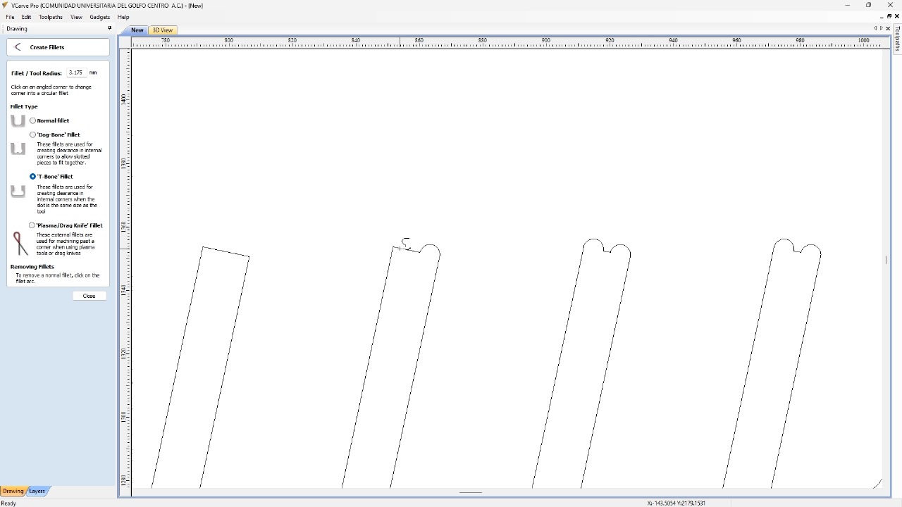
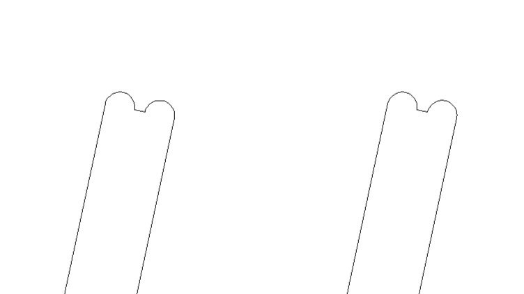
The tools here allow us to edit vectors by nodes, as well as
special cuts. T-boes and Dog-bones: helps fittings fit perfectly. Close shape: allows us to close open shapes. |
tools

 |
Cutting, punching, and engraving tools |
.png) |
1.- Simulation 2.- Estimated time 3.- Save Gcode |
.png) |
List and order of file operations |
cutting and assembly
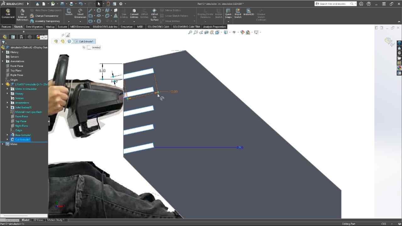
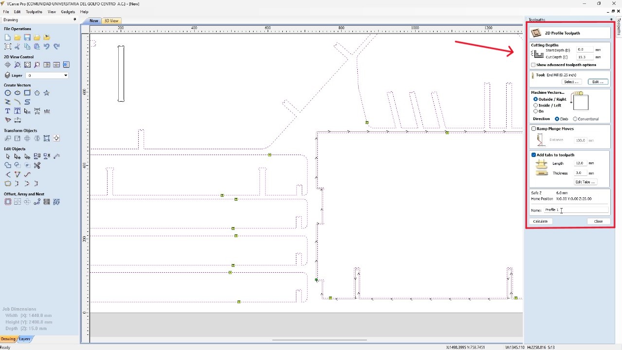
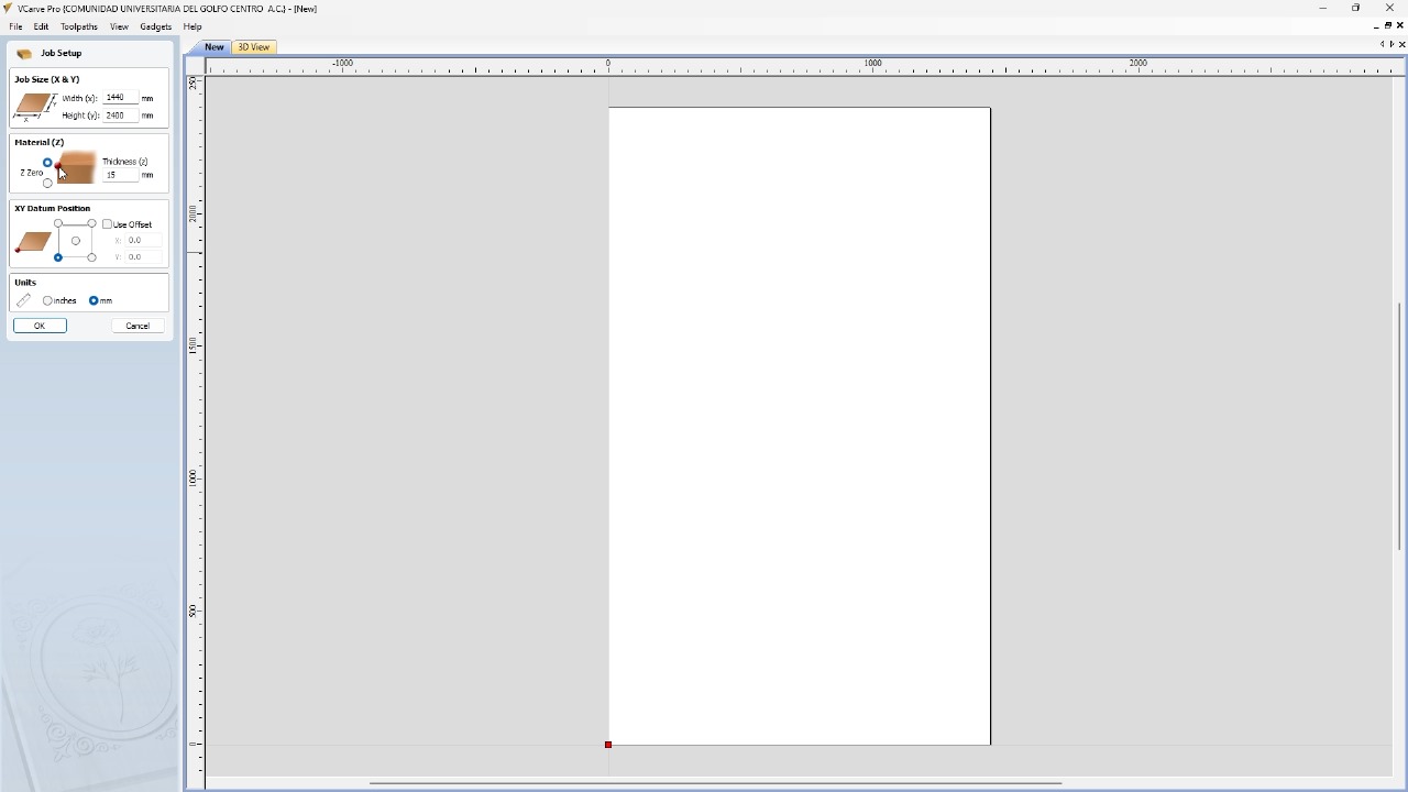
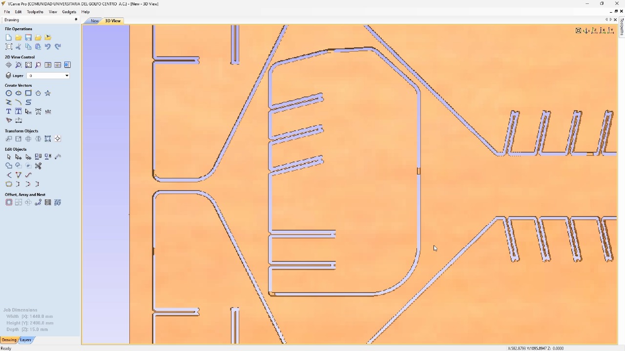
For the simulator's fabrication, I will start by configuring the program for the material I will be using, a 2.4 x 1.22 m MDF with a thickness of 15 mm and we will import the DXF that we exported from SolidWorks. Using the t-bones tool, I will fix the corners of all the pieces so that the assembly is perfect.

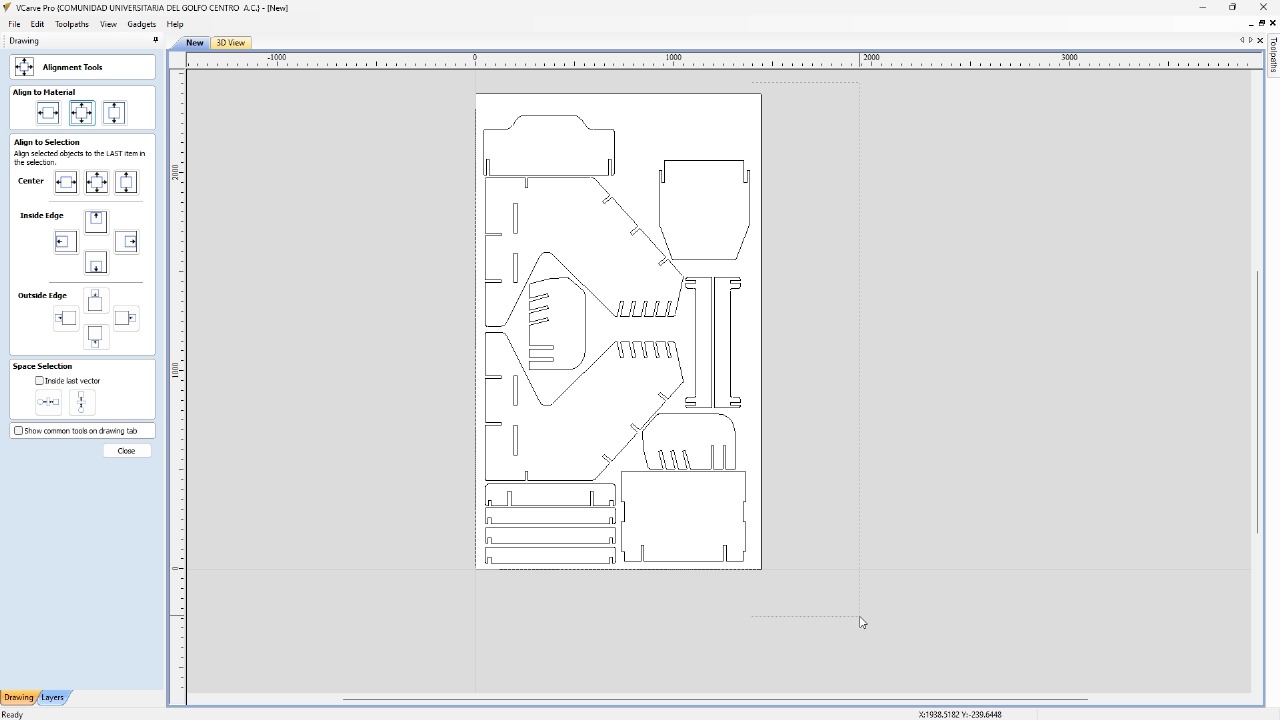

I selected all the external contours to be able to make an outside cut. In the cutting tool
configuration, I will set the depth and the number of passes. Besides selecting the cutting
tool.
This tool is a 1/4 inch mill, 4-flute. In addition to configuring
the tabs so that
the pieces do not come loose.
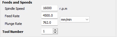
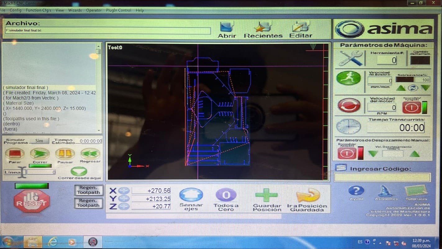
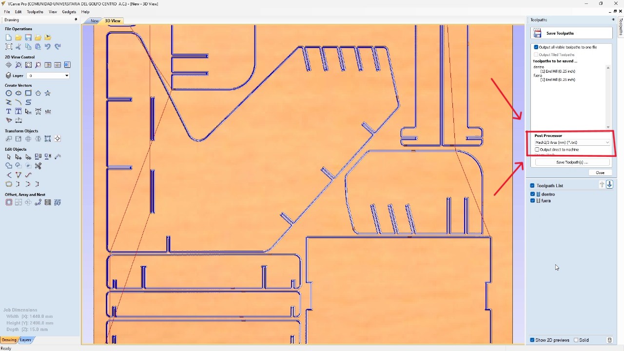
Depending on the material you got, it is important to change all the tool parametrs. Acording to the table on the group site, change the spindle speed, feed rate, number of passes, etc.I generated another operation for the internal cuts and disabled the tabs. Using the simulation tool, I tested how the cuts of my pieces would look and then exported the G Code using the processor. Mach 2/3 Arcs (mm)(txt). The machine I am using requires this post-processor to function.
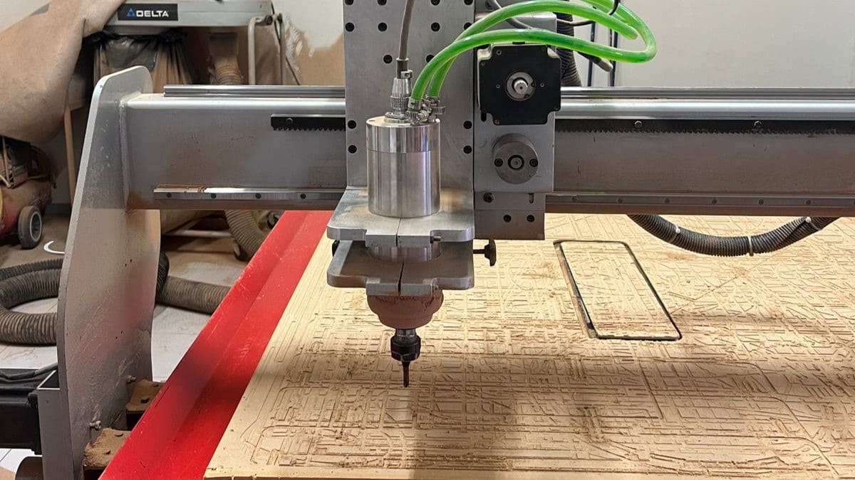
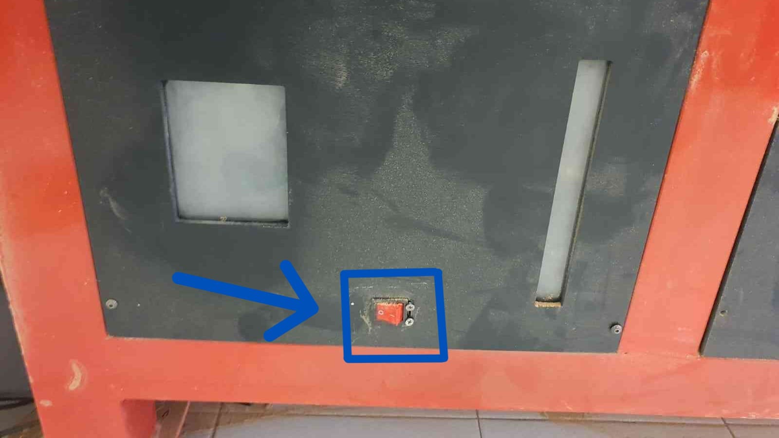
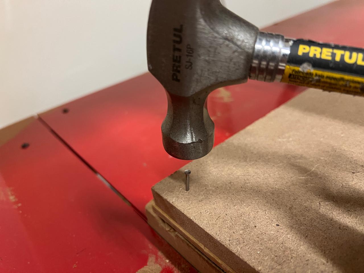
To secure the MDF to the machine bed, I used nails in the corners and sides of the MDF. And I used the machine's monitor to ensure that the path of my pieces wouldn't go over the screws. Additionally, I verified that my program was functioning correctly.
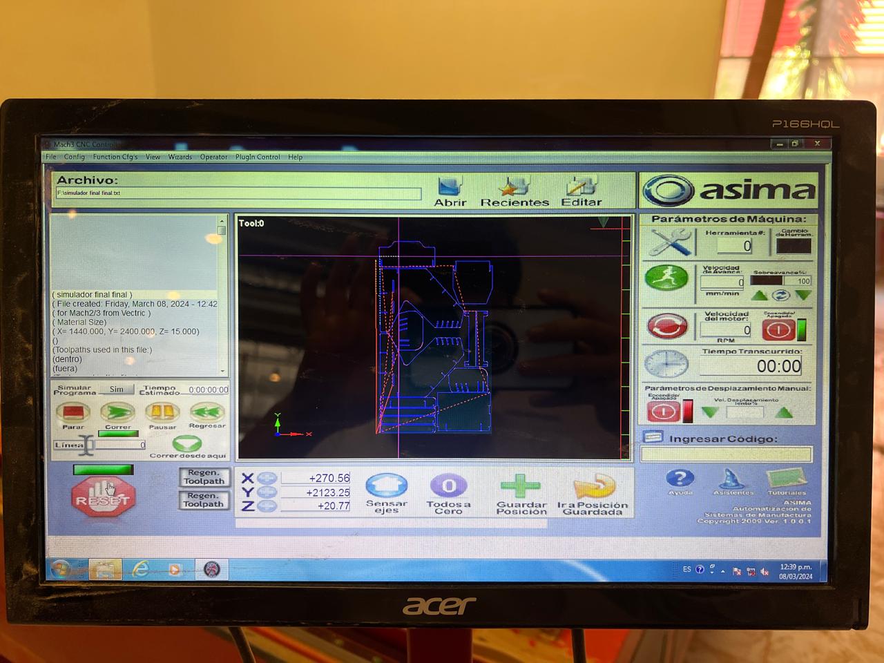
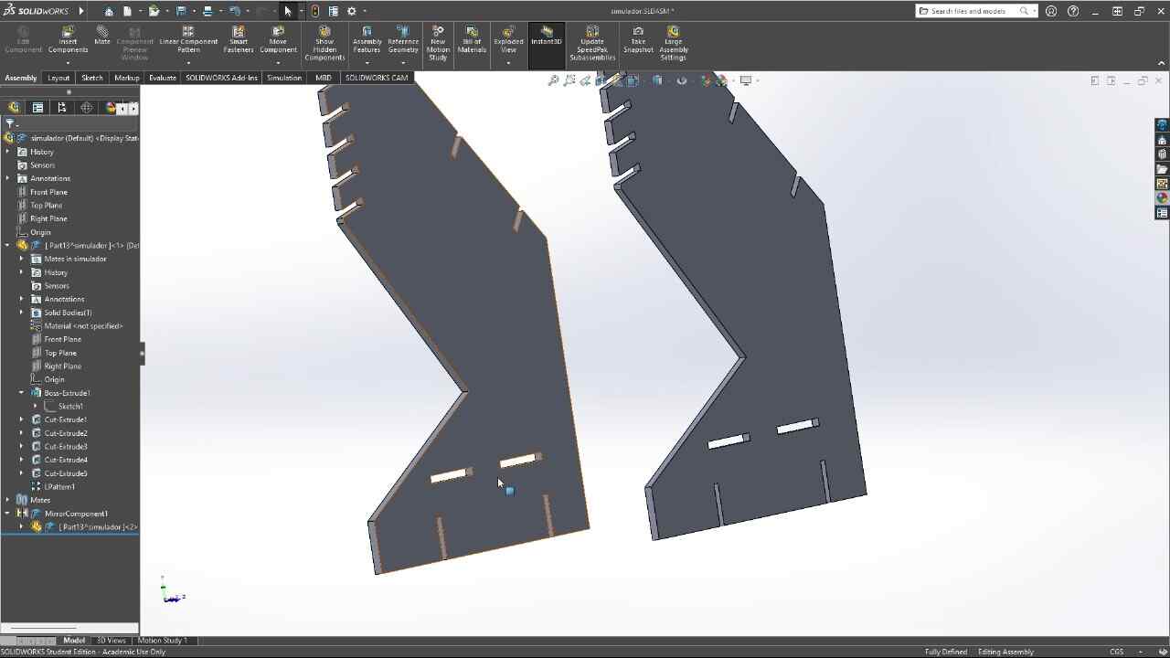
Using the .txt file that we obtained from the program, I uploaded the program to the CNC computer, proceeded to adjust the axes, and started cutting the MDF. The MDF was held in place by nails. After cutting the pieces, I started assembling them.
With the model assembled, the only thing left was to test it, so I moved it, positioned the simulator, and connected it to the computer.
The final result