

13. Networking and communications
For this week assigment we are trying connections between multiple modules. That be either wired or wireless, with the objective of interacting with input and output devices.
In my case, I will be using the I2C protocol: Inter-Integrated Circuit is a serial communication with multi controller and multi target purposes. This protocol allows us to connect multiple inputs through a limited amount of pins (Serial Data Line and Serial Clock Line). This protocol is usually connected to multiple devices, having a master and one or more slaves connected through the SDA and SCL lines.
For extra information sending messages between two projects, check the Networking and Communications Fab Ibero Puebla´s Page
So I wanted to try this protocol to experiment at a small scale the practicalities and challenges that came with it.
XIAO ESP32
The modules I will be using this week will be a ol´ trusty Arduino uno, and a brand new XIAO ESP32. We worked with XIAOs in previous weeks, but for this week I´m making a new one using an interesting technique.
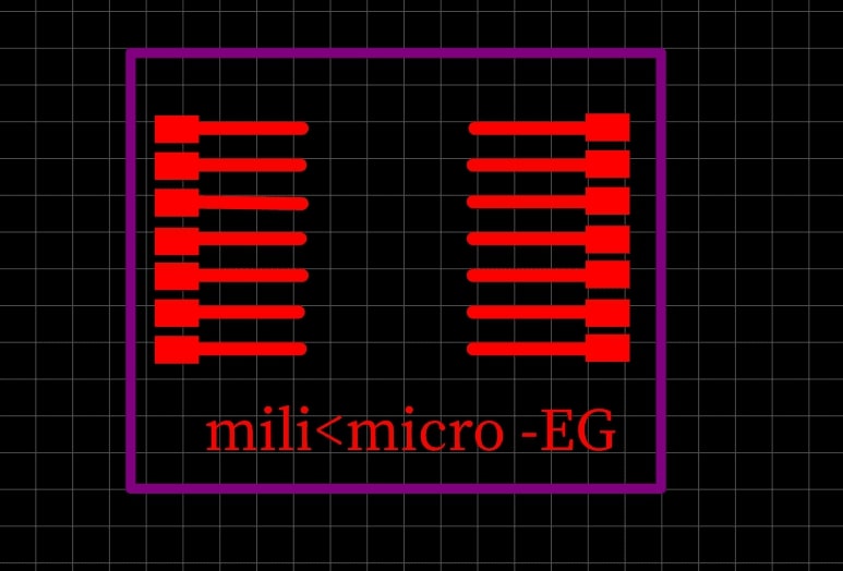
A classmate showed me how to do flexible PCBs, instead of using a phenolic board like we did with our previous PCBs, we are going to make it with the vinyl cutter. With the first step being designing the diagram in EasyEDA. I only added the XIAO footprint and their respective tracks to solder them to (and a local joke I had with a friend, don´t worry about it, it didn´t even make the finished product).
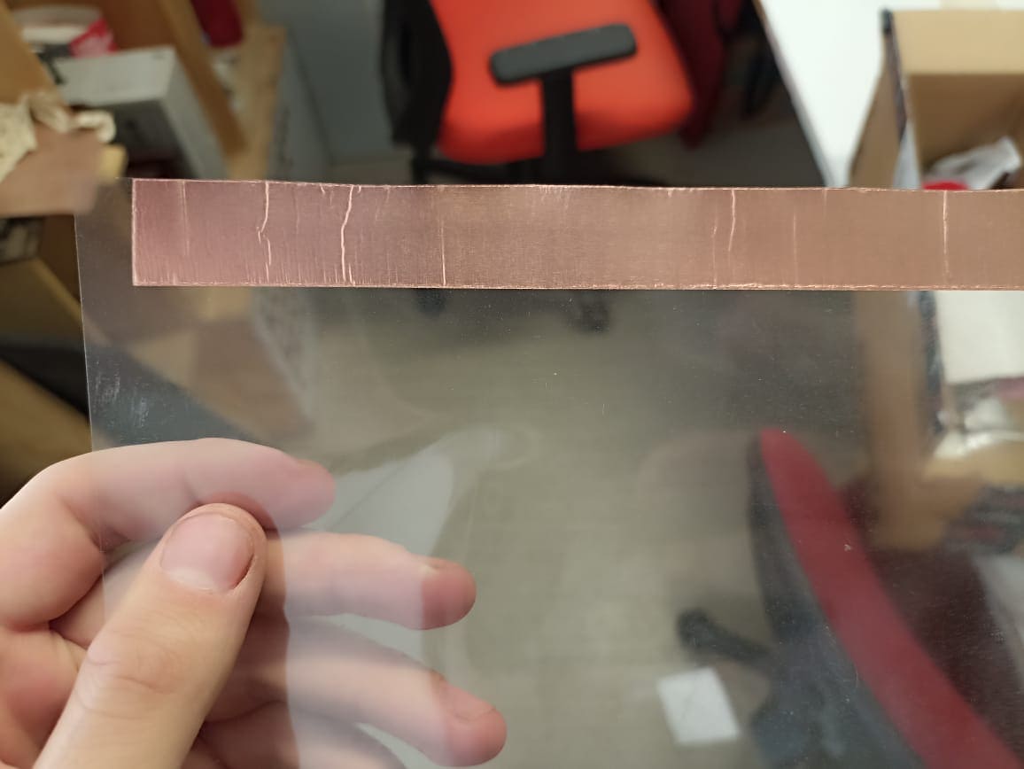
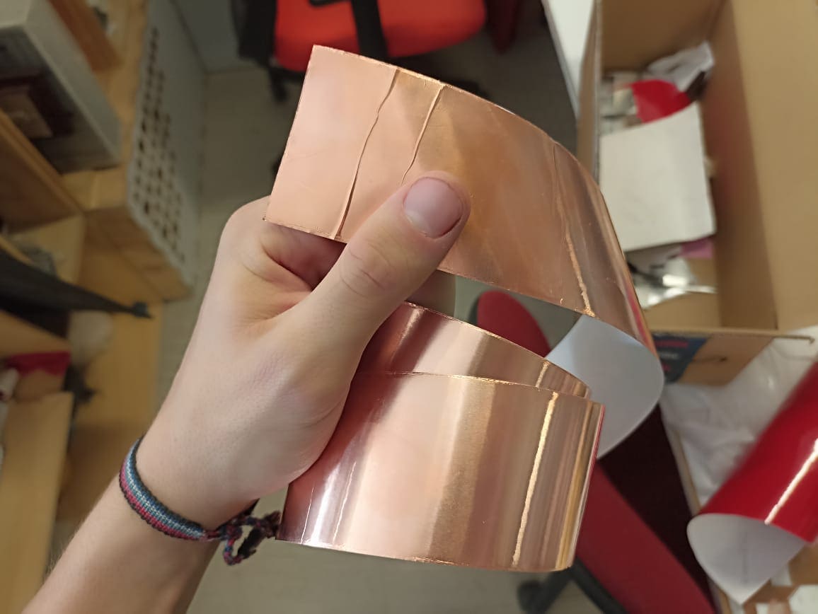
Once we have our design, we take a plastic sheet and cover it with a copper tape that adheres to it, this way we have the equivalent of the phenolic board, only this time it´s flexible.
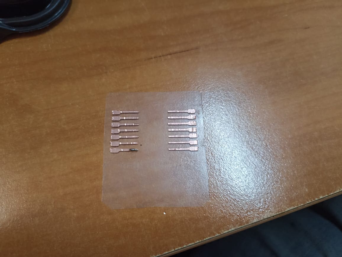
Now we do the same procedure we did in the third week with the vinyl cutter
After we take the excess off, the PCB should looks something like this: (I´m mad my joke didn´t survive the peeling :/ )
We now solder the XIAO ESP32 and their pin headers:
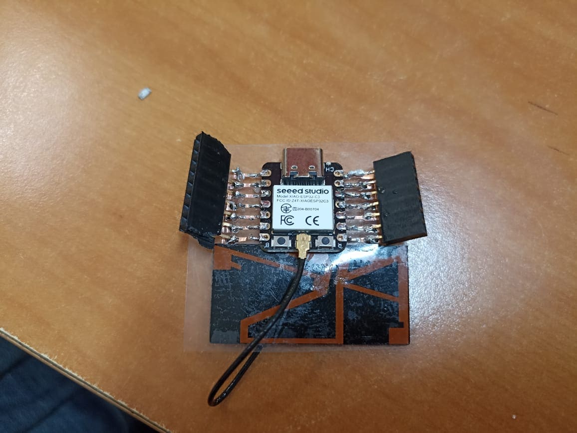
I did this so I could connect the terminals in an easier manner, but it turns out it probably was not the best idea with a flexible PCB, as the tracks are very fragile and strong movements like connecting a female pin header could damage it
I2C time...
After many tries and fails at multiple nodes, I settled for a simple 2 module potentiometer and led circuit, but it is enough to test the I2C procotol, although I will definetly will be further digging into the protocol to understand what I could to better. But the main idea is to change the brightness of the LED depending on the position of the potentiometer.
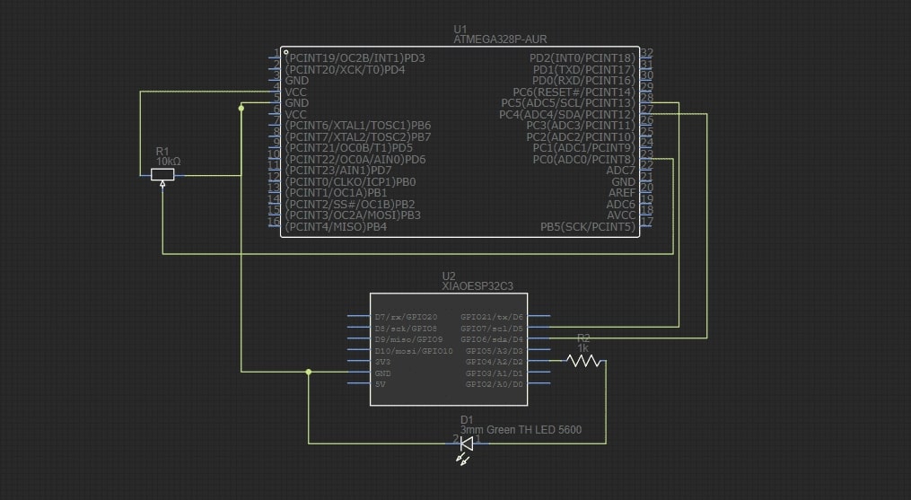
This wiring consists of the voltage line from the arduino feeding the potentiometer, a commmon ground between the 2 (this is very important, all physical communications must share a ground since it functions as a reference point, otherwise your communication won´t work). The SCL of the Arduino goes to the SCL pin of the XIAO, and the SDA of teh arduino goes to the SDA of the XIAO. The analog value from the potentiometer is read on pin 8 of the Arduino, and the led, alongside with a 330 ohm ressitor comes out of the pin 4 of the XIAO
My wiring looks very messy, and it is, so I drew this quick schematic to show what the connections do in a cleaner way:

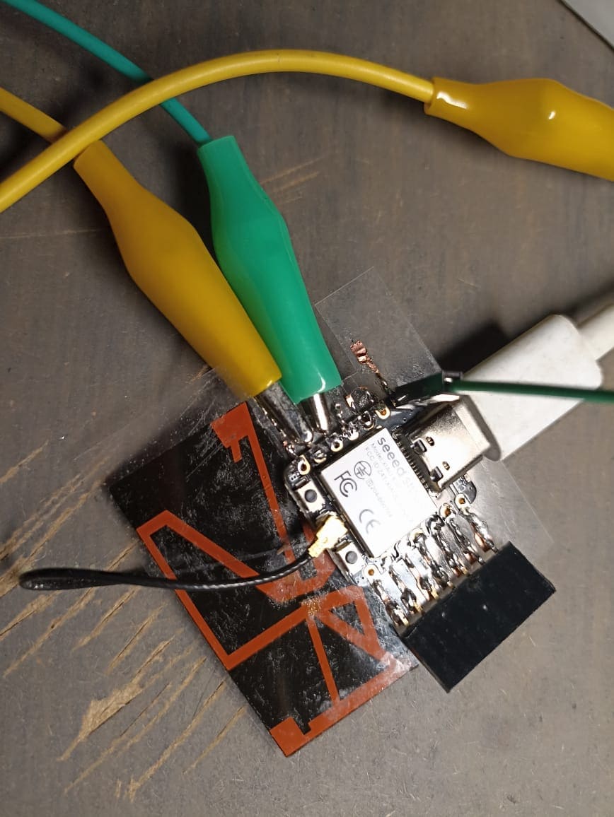
Important sidenote, altough cutting the PCB in vinyl form is a very quick and easy way of making a PCB, it is incredibly fragile to heat from the soldering iron and external forces. What ended up happening was that the left side tracks and pin headers disconnected from the XIAO, and since I did not have a soldering iron at hand, I had to improvise the SCA and SCL connections with jumper cables since they broke off due to the heat and movement of the PCB, its not pretty, and I will be making a proper PCB for the ESP32, but it got the job done.

Here I have the code; both for the Arduino (Master) and ESP32 (Slave)
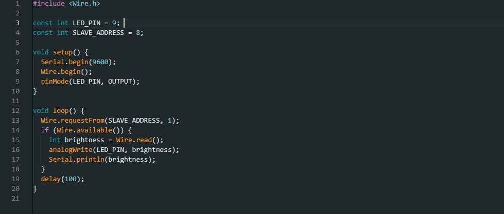
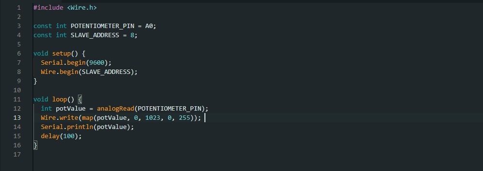
Here, the Arduino requests the data from the XIAO and stores the data in a variable, which then is used to modulate the intensity of the LED, alongside printing said value on the Serial port. The XIAO is reading the value of the potentiometer and using the map function, it translates the value from 0 to 1023 (the analog read value) to a value between 0-255, so it can be transmitted via wire to the arduino.
Here´s the video of the potentiometer reading being shown in the serial port, this is only the analog value recieved from the potentiometer itself, it´s not yet converted to the value that is transmitted to the arduino:
So when the value of the potentiometer changes, it changes the brightness of the LED.
Conclusions
I had never worked with I2C protocols before, and even though it was complicated to understand at first, it seems to be a pretty powerful way of communication multiple modules with various ammounts of information. Altough I wanted to try doing the PCB with flexible copper tape, since it is way faster to cut than in a CNC milling machine, I will probably not any more PCBs this way, since soldering components without burning the back plastic is almost impossible, even with a simple diagram like this, I can´t imagine with small SMD components. But it´s good that that I at least attempted it. I also very much disliked the wire mess I had to do, that could have been avoided if I had done a proper copper laminate PCB.